Over the Air Download (OAD)
This section serves as a guide to the Texas Instruments 15.4-Stack Over-the-Air Download (OAD) ecosystem including the custom protocol specification, application architecture, drivers, and middleware. OAD is a device firmware upgrade method that allows the firmware image running on a device to be updated over the air using a TI 15.4-Stack network while providing power loss protection.
The guide will cover the principles of the OAD process, the out of the box examples included in the SimpleLink CC13x0 SDK, and the process for adding OAD to an existing project.
The OAD guide section will cover:
The supported development kit for OAD is the CC13x0 LaunchPad. To follow the procedures listed in this guide, two CC13x0 LaunchPad development kits are required.
OAD Concept Overview
This section aims to explain the major concepts involved in the OAD process from a high level. The concepts here will be expanded upon further in the following sections. Some concepts, such as the Boot Image Manager (BIM), may vary in their implementation details. Wherever possible, the concepts will be covered in this chapter with their implementation details covered in the following chapters.
OAD Types
TI 15.4-Stack only supports off-chip OAD. During off-chip OAD, the candidate image is stored in a low power external flash and loaded into the CC13x0 internal flash by the BIM.
OAD Topology Overview
A TI 15.4-Stack network with at least one sensor node is required to run a successful OAD. The collector application must run on a linux machine using TI 15.4-Stack Linux SDK. The terms for the devices involved in an OAD exchange are listed below:
The OAD Client is always the device that implements the OAD service and is responsible for keeping track of the OAD process once it has been initiated. Typically this is the sensor device being updated. The OAD Client uses a Boot Image Manager (BIM) to facilitate the application of a new firmware update image. The BIM executes on a device reset and determines if a firmware update is to be applied. If no update is being applied, then the BIM will transfer program execution to the main application image.
The OAD Server is always the central device that notifies the OAD Client when a new image is available and supplies the firmware update. Figure 64. shows a block diagram of the OAD operations being performed on each device.
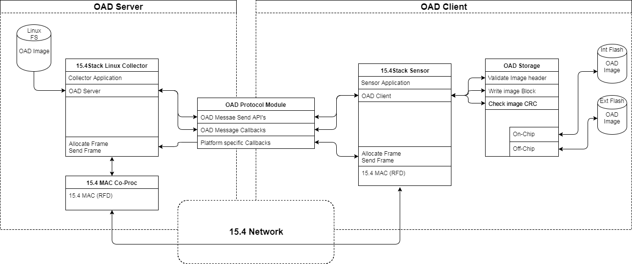
Figure 64. TI 15.4-Stack OAD Block Diagram
OAD Image Metadata
All firmware images delivered via OAD are in binary format and contain an image metadata header The information in the metadata header is used by the OAD service to determine whether or not an image is acceptable for download or by the BIM to determine which image should be loaded/executed in the main system flash. In order to prevent this information from being calculated multiple times all TI OAD images use a standard 16-byte metadata vector. This metadata vector is embedded at the beginning of the image, occupying the first 16 bytes before the application code firmware content.
This section explains the various fields within the metadata vector and what they mean.
Most metadata checking is done in OADTarget_validateNewImage().
TI provides a tool to generate an OAD ready image, which contains a metadata vector called the OAD Image Tool. See OAD Image Creation.
Table 18. below shows a description of the metadata vector.
| Field | Size (in bytes) | Description |
|---|---|---|
| CRC | 2 | Cyclic Redundancy Check |
| CRC Shadow | 2 | Place holder for CRC |
| Version | 2 | Version |
| Length | 2 | Length of the image in words* |
| UID | 4 | User Identification |
| Start Address | 2 | The destination address of the image in words* |
| Image Type | 1 | The type of image to be downloaded |
| State | 1 | The status of this image |
| [*] | These fields are measured in 32-bit words. For example, an image length of 0x100
describes an image that is 1024 bytes in size. This OAD word size is
defined by |
CRC and CRC Shadow
The cyclic redundancy check (CRC) is a means to check the integrity of an image. This must be done in two steps. First the CRC must be calculated when the image is generated from the toolchain, this will be stored in the CRC field within the metadata vector.
This initial CRC will be sent over the air via the OAD Protocol.
Later, once the target has received the OAD image, CRC shadow will be calculated to determine if the image has been corrupted during transfer. The target will re-calculate the CRC of the downloaded image and store the result in the CRC shadow field of the metadata vector.
If the CRC and CRC shadow are equivalent, the target can assume that the image was not corrupted while sending over the air.
The algorithm selected for CRC calculations is the CRC-16-CCITT, it is a 16 bit CRC calculation that has a 99.9984% error detection rate in the worst case. In addition to this CRC, all data transfers in TI 15.4-Stack are protected by a CRC on the link layer so the risk of an undetected data corruption is even further reduced.
Version
The image version field is used to track revisions of images and ensure
upgrade compatibility. Customers may implement their own versioning
scheme; however, there are additional checks imposed by the TI OAD profile.
See the function OADTarget_validateNewImage() within
oad_target_external_flash.c to see
how these version checks are done in Off-chip OAD.
Length
The length field is the length of the image in words, where the word
size is defined by EFL_OAD_ADDR_RESOLUTION
for Off-chip OAD. Off-chip OAD customers who
are using different external flash parts may need to modify
EFL_OAD_ADDR_RESOLUTION to match the word size of their part.
User Identification (UID)
This field is un-used by the TI OAD profile, but the hooks are in place for a customer to add their own implementation of verifying images based on UID.
Off-chip images use ‘E’, ‘E’, ‘E’, ‘E’ by default.
Start Address
The start address is the first address where the proposed image is to be stored in internal flash. Similar to the length field, this is calculated in words. Off-chip OAD solutions put restrictions on the start address based on image type (more on this in the next section).
Image Type
TI 15.4-Stack only support APP+STACK merged updates.
OAD Client
The OAD client module has been designed to provide a simple and customizable implementation for the customer. In its most rudimentary form, this module is responsible for accepting/rejecting an OAD interaction based on image header criteria, storing the image in its appropriate location, and causing a device reset if the download is successful so that the downloaded application image is run by the BIM.
The OAD Client module provides a service to process and generate application events for OAD Client functionality, it is specific to a 15.4Stack application. It houses the code required for the application to act as an OAD client, reducing the code needing to be added in the application files. The OAD Client uses the services provided by the OAD_Protocol and OAD_Storage modules.
Flash Layout
Table 19. shows the default flash layout for an OAD Client. The default configuration is common across BLE, therefore; a CC1350 can be update via BLE OAD or TI 15.4-Stack OAD.
| Section | Flash Range |
|---|---|
| BIM Reset Vectors | 0x0 - 0x3C |
| BIM Driver Lib | 0x3D - 0xFFF |
| OAD Image Header (metadata) | 0x1000 - 0x100F |
| Application Reset Vectors | 0x1010 - 0x104C |
| Application Image | 0x104D - 0x1CFFF |
| NV Storage | 0x1D000 - 0x1EFFF |
| BIM | 0x1F000 - 0x1FF89 |
| CCA | 0x1FF8A - 0x1FFFF |
If interoperability is not a requirement and TI 15.4-Stack OAD is the only method being used, then an addition 5.5KB of flash can be saved by using TI-RTOS in ROM. When TI-RTOS is running from ROM it assumes that there is constant data placed at the beginning of page 1 (0x1000), which means a link conflict occurs when using the default flash layout. To prevent this conflict the internal flash layout can be rearranged, but this breaks compatibility with BLE and EasyLink OAD. To enable this optimization to the following:
Modify the BIM CCS project by adding
TIRTOS_IN_ROMto Project->Properties->Arm Compiler->Predefined SymbolsModify the sensor_oad application:
- Add
TIRTOS_IN_ROMProject->Properties->Arm Compiler->Predefined Symbols - Add
TIRTOS_IN_ROMto Project->Properties->Arm Linker->Advanced Options->Command File Processing - Add
NO_ROM=1to Project->Properties->XDCtools->Advanced Options->Configuration Script Arguments
- Add
The resulting flash layout is shown in Table 20..
| Section | Flash Range |
|---|---|
| BIM Reset Vectors | 0x0 - 0x3C |
| BIM Driver Lib | 0x3D - 0xFFF |
| RCFG (TI-RTOS constants) | 0x1000 - 0x14EF |
| OAD Image Header (metadata) | 0x14F0 - 0x14FF |
| Application Reset Vectors | 0x1500 - 0x153C |
| Application Image | 0x153D - 0x1CFFF |
| NV Storage | 0x1D000 - 0x1EFFF |
| BIM | 0x1F000 - 0x1FF89 |
| CCA | 0x1FF8A - 0x1FFFF |
Initialization
In order for the OAD Client module to process and generate application events it needs to be initialized with an event handle used to set event masks as they occur and the applications semaphore that can be used to wake up the application after an event is set.
OADClient_init() must be called before the module can process OAD events.
The following parametric configuration is passed:
/** @brief RF parameter struct
*  RF parameters are used with the SOADProtocol_open()
*   and SOADProtocol_Params_init() call.
*/
typedef struct {
    uint16_t *pEvent;             ///< Event handle to post to
    ICall_Semaphore eventSem;    ///< Semaphore to post event
} OADClient_Params_t;
Application Interface
The OAD_Client module formats and parses the OAD messages. The following API is exposed:
/** @brief  Function to open the OADProtocol module
*
*  @param  params      An pointer to OADClient_Params_t structure
*  for initialization
*/
extern void OADClient_open(OADClient_Params_t *params);

/** @brief  Function to process OAD events
*
*  @param  pEvent      Event to process
*/
extern void OADClient_processEvent(uint16_t *pEvent);

/** @brief  Function abort OAD
*
*  @param  resume      set to true if a auto resume is required
*/
void OADClient_abort(bool resume);

/** @brief  Function abort OAD
*
*  @param  delay      time in ms to start resume
*/
void OADClient_resume(uint32_t delay);
Example Function Trace
Figure 65. shows the typical function flow for an OAD Client to send a message from the Application through the OAD_Client and OAD_Protocol modules to the MAC API.
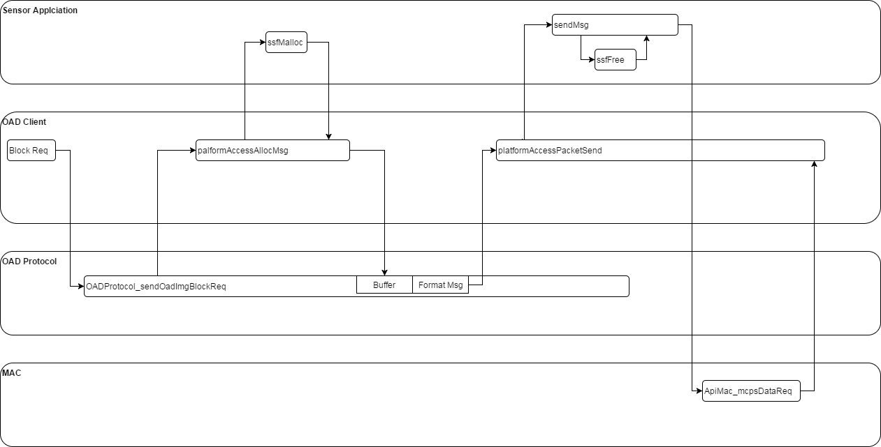
Figure 65. Block Request message flow.
Figure 66. shows the typical function flow for an OAD Client receiving a messge from the OAD Server.
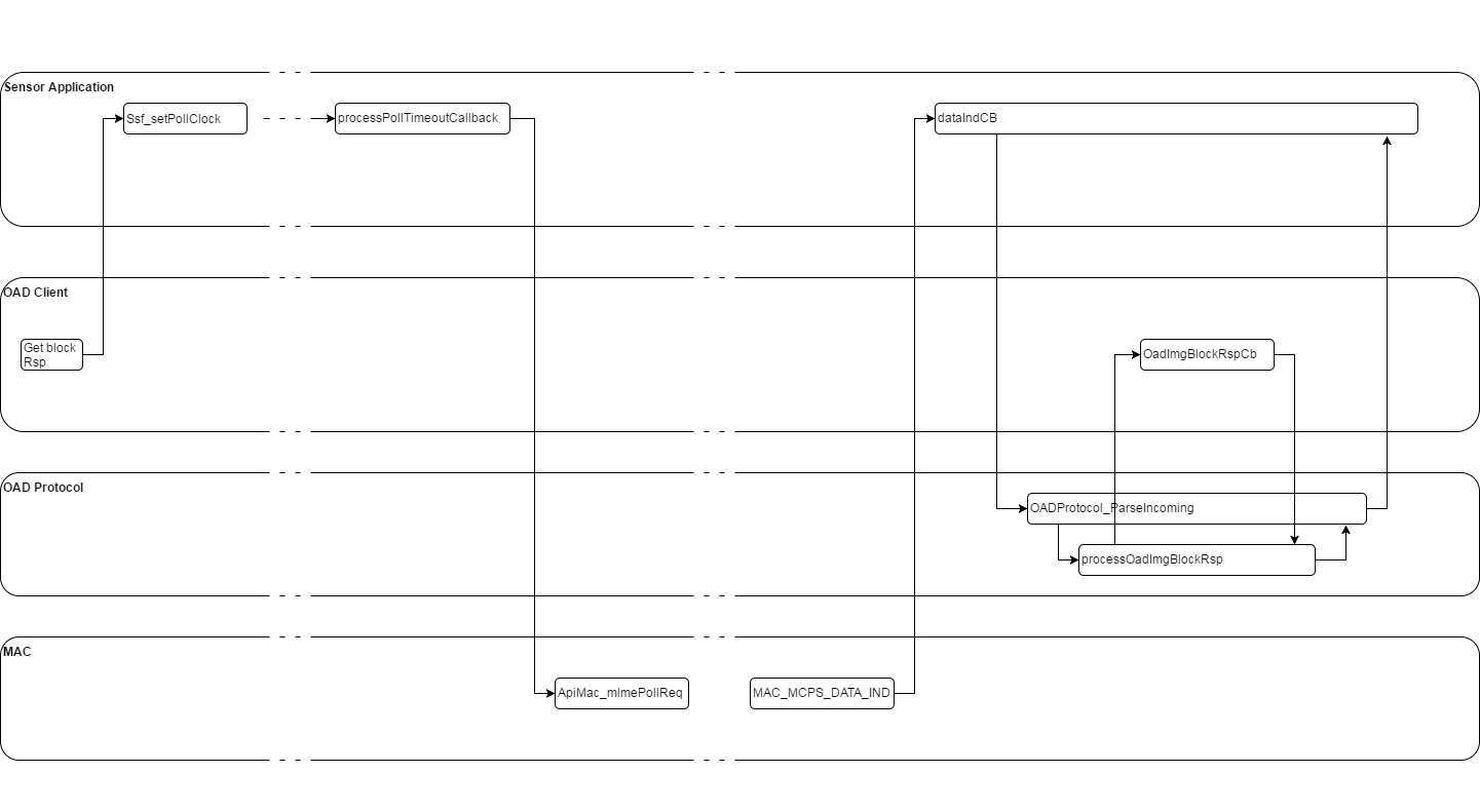
Figure 66. Block Response processing.
OAD Server
OAD Server functionality is provided by the Linux Collector Application, part of
the TI 15.4-Stack Linux SDK. When the collector application is built without
the IS_HEADLESS flag an interactive command-line interface to the
collector application exposes the following functionality:
- Devices can be selected
- A firmware file can be selected for transfer
- LED toggle requests can be sent to the selected device
- Version requests can be sent to the selected device
- Firmware update requests can be sent to the selected device
A typical view of this interface
TI Collector
Nwk: Started
Sensor 0x0001: Temp 25, RSSI -18
Sensor 0x0002: OAD Block 211 of 960


Info: Sending 0x0002 FW update Req
cmd: u
The available commands are:
- sxx: Select a device. Example ‘s1’ or ‘s0x1234’
- o: Open or close the network for new devices to join
- t: Send an LED toggle request to selected device
- v: Send a version request to selected device
- u: Send FW update request to selected device
- fxx: Set FW file from configured OAD FW dir. Example ‘f sensor_mac_oad_cc13x0lp_app_v2.bin’
OAD Storage
The OADStorage interface provides device independent APIs, data types, and macros for Storing the OAD image. The OADStorage module calls into oad_target, which provide the device dependent functionality to write the OAD image into flash. oad_target only contains the support for external (off-chip) OAD Image storage.
Initilization
OADStorage_init() must be called before any other OADTarget APIs.
Application Interface
The OAD Storage module exposes the following API for staring the OAD image:
/*********************************************************************
 * @fn      OADStorage_init
 *
 * @brief   Initialise the OAD Target Profile.
 *
 * @param   None.
 *
 * @return  None.
 */
extern void OADStorage_init(void);

/*********************************************************************
 * @fn      OADStorage_imgIdentifyWrite
 *
 * @brief   Process the Image Identify Write.  Determine from the received OAD
 *          Image Header if the Downloaded Image should be acquired.
 *
 * @param   pValue     - pointer to data to be written
 *
 * @return  status
 */
extern OADStorage_Status_t OADStorage_imgIdentifyWrite(uint8_t *pValue);

/*********************************************************************
 * @fn      OADStorage_imgBlockWrite
 *
 * @brief   Process the Image Block Write.
 *
 * @param   connHandle - connection message was received on
 * @param   pValue - pointer to data to be written
 *
 * @return  status
 */
void OADStorage_Status_t OADStorage_imgBlockWrite(uint8_t *pValue);

/*********************************************************************
 * @fn      OADStorage_imgFinalise
 *
 * @brief   Checks the image CRC and marks the image for use. The BIM
 *          will than copy the image (for off-chip) and execute.
 *
 * @param  none
 *
 * @return  status
 */
OADStorage_Status_t OADStorage_imgFinalise(void);

/*********************************************************************
 * @fn      OADStorage_close
 *
 * @brief   Releases the resource required for OAD storage.
 *
 * @param  none
 *
 * @return none
 */
void OADStorage_close(void);
OAD Protocol
The OAD protocol module is based on the principle that the OAD Server initiates the OAD process and the OAD Client requests the OAD FW image blocks. The OAD client is responsible for requesting image blocks and handling error conditions if they occur. The OAD Client will re-requesting image block when required. Once the OAD has completed the OAD Client will reset and start running the new image.
The OAD Protocol Interface provides device independent APIs, data types, and macros. The APIs in this module serve as an interface to a TI-RTOS application and offers functionality for an OAD messaging protocol between an OAD Sever and OAD Client. The module handles the formatting / parsing of messages.
Initializing the OAD Protocol Module
In order to use the OAD Protocol APIs, the application is required to provide application specific configuration and callbacks. For the application to process OAD Messages the following callback table must be provided:
/** @brief OADProtocol callback table
 *
 */
typedef struct
{
    fwVersionReqCb_t      pfnFwVersionReqCb; ///< Incoming FW Req
    fwVersionRspCb_t      pfnFwVersionRspCb; ///< Incoming FW Version Rsp
    oadImgIdentifyReqCb_t pfnOadImgIdentifyReqCb; ///< Incoming Image IdentifyReq
    oadImgIdentifyRspCb_t pfnOadImgIdentifyRspCb; ///< Incoming Image IdentifyRsp
    oadBlockReqCb_t       pfnOadBlockReqCb; ///< Incoming OAD Block Req
    oadBlockRspCb_t       pfnOadBlockRspCb; ///< Incoming OAD Block Rsp
} OADProtocol_MsgCBs_t;
For the OAD module to allocate buffers and send messages the following platform specific call back must be provided:
/** @brief OADProtocol platform access functions
 *
 */
typedef struct
{
    plaformAccessAllocMsg_t         pfnRadioAccessAllocMsg;   ///< Function for allocating a message buffer
    platformAccessPacketSend_t      pfnRadioAccessPacketSend; ///< Function for sending message over the radio
} OADProtocol_PlatformAccessFxns_t;
OADProtocol_init() must be called before any other OADProtocol APIs. The
following parametric configuration is passed:
/** @brief RF parameter struct
 *  RF parameters are used with the OADProtocol_open() and OADProtocol_Params_init() call.
 */
typedef struct {
    OADProtocol_PlatformAccessFxns_t  *pPlatformAccessFxns;    ///< Platform access function table
    OADProtocol_MsgCBs_t              *pProtocolMsgCallbacks;  ///< Application Callbacks for pressing packets
} OADProtocol_Params_t;
Application Interface
The OAD Protocol module formats and parses the OAD messages. The following API is exposed:
/** @brief  Function to initialize the OADProtocol_Params struct to its defaults
 *
 *  @param  params      An pointer to RF_Params structure for
 *                      initialization
 *
 *  Defaults values are:
 *      maxretires          = OADProtocol_DEFAULT_MAX_RETRIES
 *     pRadioAccessFxns     = {0}
 *      pCallbacks          = {0}
 */
extern void OADProtocol_Params_init(OADProtocol_Params_t *params);

/** @brief  Function that initializes the Wsn Protocol Task and creates all TI-RTOS objects
 *
 */
extern void OADProtocol_init(void);

/** @brief  Function to open the OADProtocol module
 *
 *  @param  params      An pointer to RF_Params structure for initialization
 */
extern void OADProtocol_open(OADProtocol_Params_t *params);

/** @brief  Function to parse OADProtocol packets
 *
 *  @param  srcAddr             address of the device that sent the message
 *  @param  incomingPacket      pointer to packet to be parsed
 *  @param  packetLen           length of the message
 */
extern OADProtocol_Status_t OADProtocol_ParseIncoming(void* pSrcAddr, uint8_t* incomingPacket, uint8_t packetLen);


/** @brief  Function to send a FW version request packet
 *
 *  @param  dstAddress          Address to send the request to
 *
 *  @return                     Status
 */
extern OADProtocol_Status_t OADProtocol_sendFwVersionReq(void* pDstAddress);

/** @brief  Function to send a FW version response packet
 *
 *  @param  dstAddress          Address to send the response to
 *  @param  fwVersion           Firmware version string to send
 *
 *  @return                     Status
 */
extern OADProtocol_Status_t OADProtocol_sendFwVersionRsp(void* pDstAddress, char *fwVersion);

/** @brief  Function to send an OAD image identify request packet
 *
 *  @param  dstAddress          Address to send the request to *
 *  @param  imgId               image ID used for requesting image blocks
 *  @param  pImgInfoData        Image header
 *
 *  @return                     Status
 */
extern OADProtocol_Status_t OADProtocol_sendImgIdentifyReq(void* pDstAddress, uint8_t imgId, uint8_t *pImgInfoData);

/** @brief  Function to send an OAD image identify request packet
 *
 *  @param  dstAddress          Address to send the response to
 *  @param  status              status to send
 *
 *  @return                     Status
 */
extern OADProtocol_Status_t OADProtocol_sendOadIdentifyImgRsp(void* pDstAddress, uint8_t status);

/** @brief  Function to send an OAD block request packet
 *
 *  @param  dstAddress          Address to send the request to
 *  @param  imgId               image ID of image blocks
 *  @param  blockNum            block Number to request
 *  @param  multiBlockSize      Numer of blocks in the multi Block transfer (0 or 1 for none-multiblock)
 *
 *  @return                     Status
 *
 */
extern OADProtocol_Status_t OADProtocol_sendOadImgBlockReq(void* pDstAddress, uint8_t imgId, uint16_t blockNum, uint16_t multiBlockSize);

/** @brief  Function to send an OAD block response packet
 *
 *  @param  dstAddress          Address to send the response to
 *  @param  imgId               image ID of image blocks
 *  @param  blockNum            Block number
 *  @param  block               pointer to image block
 *
 *  @return                     Status
 *
 */
extern OADProtocol_Status_t OADProtocol_sendOadImgBlockRsp(void* pDstAddress, uint8_t imgId, uint16_t blockNum, uint8_t *block);
Usage
To use the OAD Protocol module to format/parse OAD messages, the application calls the following APIs:
- OADProtocol_init(): Initialize the OADProtocol module/task
- OADProtocol_Params_init(): Initialize a OADProtocol_Params structure with default values. Then change the parameters from non-default values as needed.
- OADProtocol_open(): Open an instance of the OADProtocol module, passing the initialized parameters.
- OADProtocol_sendFwRequest(): This is an example of an OAD message that is formated and sent.
The following code example opens OADProtocol, sends a FW version request and processes the response.:
OADProtocol_packetCBs_t OADProtocolCbs = {
  NULL, //Incoming FW Req
  fwVersionReqCb, //Incoming FW Version Rsp
  NULL, //Incoming Image Identify Req
  NULL, //Incoming Image Identify Rsp
  NULL, //Incoming OAD Block Req
  NULL, //Incoming OAD Block Rsp
  NULL, //Error callback
};

static void fwVersionRspCb(uint16_t srcAddr, char *fwVersionStr)
{
  //Do something with srcAddr and fwVersionStr
}

void someTaskInit(void)
{
  OADProtocol_init();
}

void someTaskFxn(void)
{
  // Set Default parameters structure
  static OADProtocol_Params_t OADProtocol_params;

  // Initialize and open the Wsn Protocol Task
  OADProtocol_Params_init(&OADProtocol_params);
  OADProtocol_params.pCallbacks = &OADProtocolCbs;
  OADProtocol_params.devType = OADProtocol_DevType_Concentrator;
  OADProtocol_params.devAddress = OADProtocol_CONCENTRATOR_ADDRESS;
  OADProtocol_open(&OADProtocol_params);

  OADProtocol_sendFwVersionReq(nodeAddress);

}
OAD Messages
The OAD Protocol module uses requests and responses between the OAD Server and Client. The supported messages are described in Table 21..
| Message | Client | Server | Description |
|---|---|---|---|
| FwVersionReq | no | yes | Request Firmware version of an OAD Client node. |
| FwVersionRsp | yes | no | Response sent from an OAD Client node contatining the firmware version currently running. The OAD Server uses this information to determine if an update is nessisary. |
| ImgIdentifyReq | no | yes | Request containing the OAD header of the new FW image sent to a specific OAD client node. |
| ImgIdentifyRsp | yes | no | Response from the OAD client node. If the OAD image header is accepted by the OAD client node then the response will contain a success status, if not it will contain a fail status. The reasons for an OAD client node to send a fail status could include: Invalid image type, Invalid version (Client is running a newer version), or Invalid binary size. |
| SendOadImgBlockReq | yes | no | If the OAD client node accepts the image header in the ImgIdentifyReq then it will request OAD blocks using the SendOadImgBlockReq. The OAD client will implement a timeout for the SendOadImgBlockRsp and will re-request the OAD block n times if a timeout occurs. |
| SendOadImgBlockRsp | no | yes | The requested OAD block will be sent by the OAD server in a SendOadImgBlockRsp. The SendOadImgBlockReq’s and SendOadImgBlockRsp’s will continue until all blocks have been received by the OAD client. Default OAD_BLOCK_SIZE = 128. |
OAD Protocol Message Flow
Figure 67. show the flow of OAD messages throughout the entire OAD process.
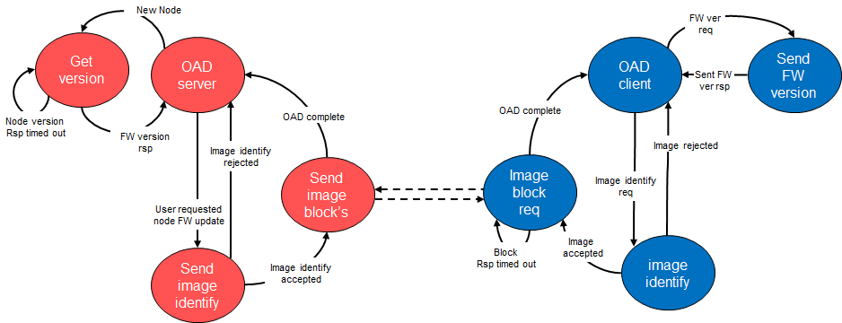
Figure 67. OAD Protocol Flow Diagram
The following sequence diagrams illustrate the communication between an OAD Server and OAD Client. These assume the OAD Server is a FFD and the OAD Client is a RFD.
FW Version
The FW version is requested by the application on the Server and responded to by the Application on the Client. The Client will only receive the request when it sends a Data Request to the Server.
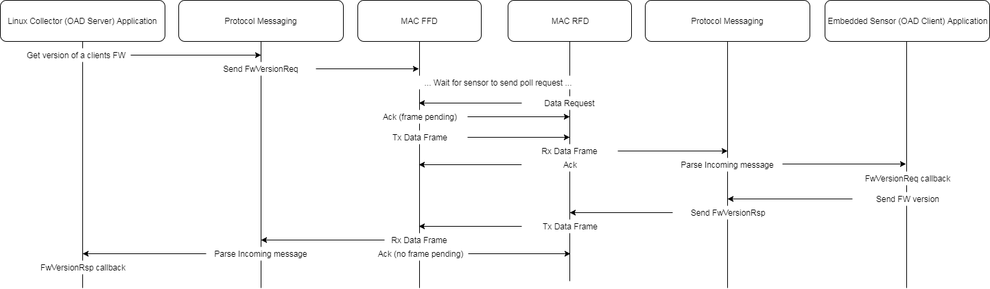
Figure 68. FwVersionReq and FwVersionRsp
Initiating OAD
An OAD is initiated by the OAD Server and is accepted by the OAD Client. The client will only receive the request when it sends a Data Request to the server. The OAD Initiate request will only be accepted by the client if the image header in the request is valid.
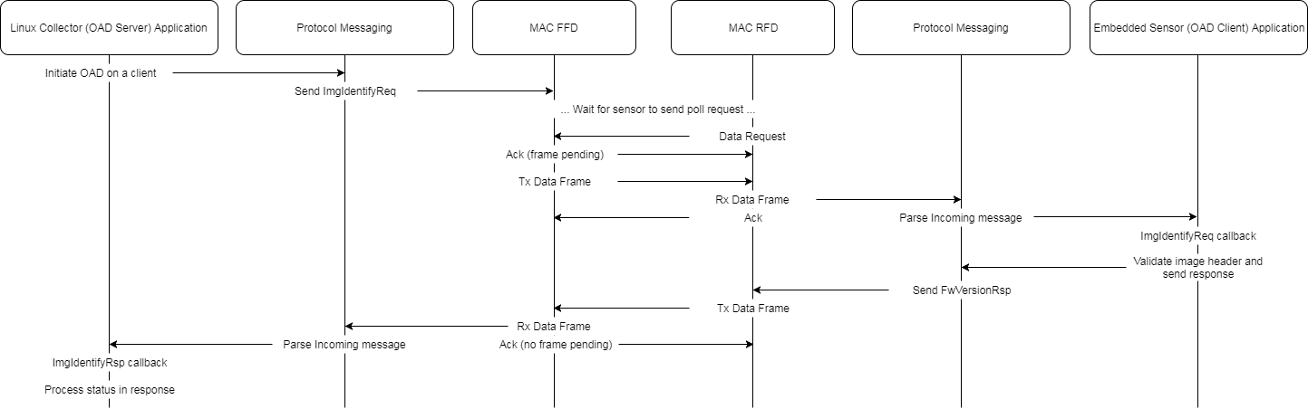
Figure 69. OAD process being initiated.
OAD Block Transfers
An OAD Client sends a Image Block Request to to OAD Server. There are three possible outcomes of this request:
- A single block is transfered successfully
- A single block is transfered, but requires multiple poll requests
- A request time-out occurs and the request is retried
Figure 70. illustrates a successful block transfer.
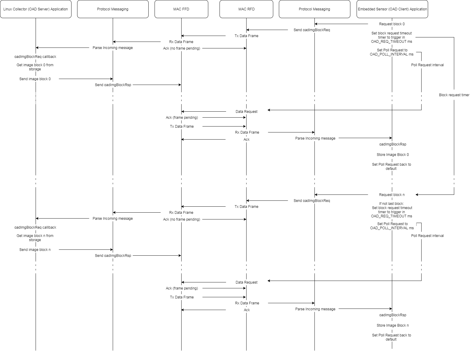
Figure 70. Single Block Transfer.
Figure 71. illustrates a successful block transfer, but requires multiple poll requests because the OAD Server did not send an oadImgBlockRsp before the first poll request.
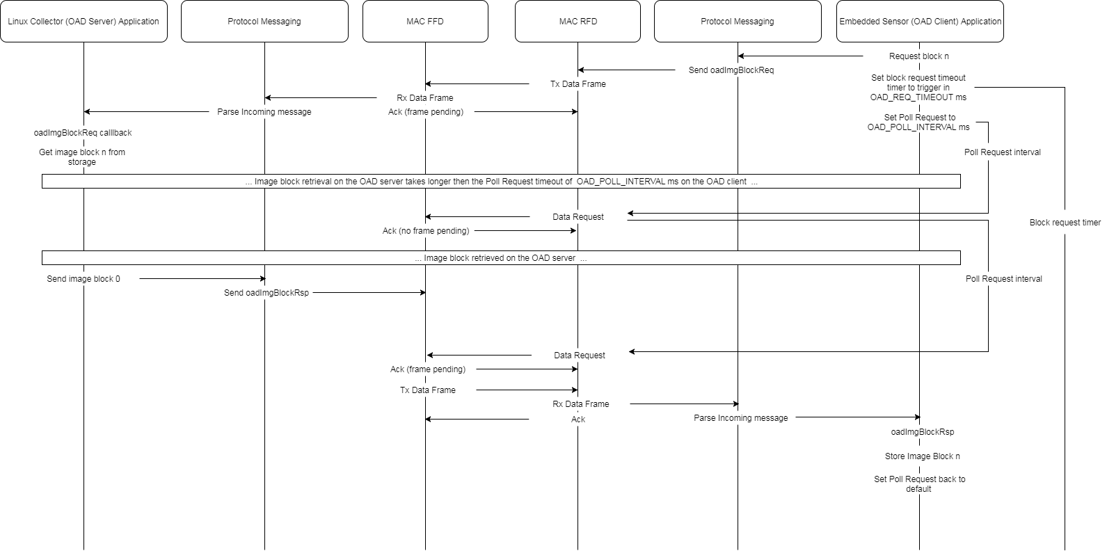
Figure 71. Single Block Transer with Multiple Poll Requests.
Figure 72. illustrates a failed block request followed by a retry.
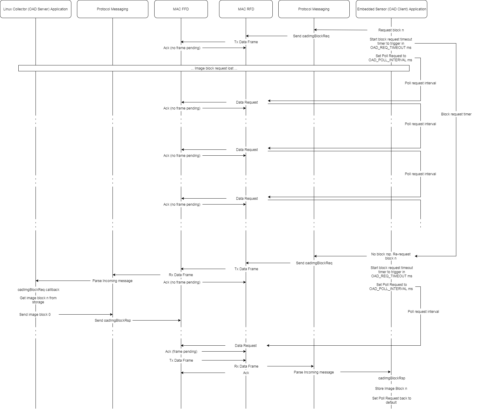
Figure 72. Single Block Timeout and is Retried.
OAD Configurable Parameters
The following parameters can be configured at compile-time:
- OAD_POLL_INTERVAL: This define is measured in ms and controls the timing on the OAD Client from the sending the Block Request to sending the poll request for the OAD Block Response. A smaller OAD_POLL_INTERVAL decreases the amount of time the OAD Block is queued in the collector and hence the chance that the collector will suffer a buffer overflow. However the Collector will take a finite amount of time to retrieve the OAD block, and queue the OAD Block Response, so care must be taken to make the OAD_POLL_INTERVAL long enough to allow the collector to retrieve the OAD block after receiving the OAD Block request. It is advisable to make this as small as possible in large networks where the collector needs to queue messages for many RFD’s.
- OAD_REQ_TIMEOUT: This define is measured in ms. It defines the amount of time on the OAD Client between 1 block request and the next block request. Reducing this will reduce the time taken to send an OAD. How quickly the OAD takes to complete is application dependent, severaly power constrained devices may need large periods between block req to allow the power source to recover. Other applications may require the OAD to complete quickly, such as in systems where a service engineer is required to performing the OAD.
- OAD_BLOCK_SIZE: This define also effects the time taken to complete the OAD. The OAD_BLOCK_SIZE is the number of bytes sent in an OAD Block and can be a minimum of 16 and a maximum of 496B. Care must be taking when setting this to a high value in environments where noise is a concern, as the chances of a block being corrupted due to an interfere increases with the size of the block.
TI 15.4-Stack OAD Example
To be safe when using for the first time the external flash of the sensor should be wiped. Program both LP boards with CC1350LaunchPad_ExtFlashErase.hex. The program will flash the LED’s while erasing and once finished the LED’s will stop flashing. Allow the application to run until the external flash has been erased and the LED’s stop flashing.
The wipe flash FW can be found in below location and should be downloaded with SmartRF Flash Programmer:
C:\ti\simplelink_cc13x0_sdk_1_50_00_xx\examples\rtos\CC13X0_LAUNCHXL\ti154stack\hexfiles\oad\CC1350LaunchPad_ExtFlashErase.hex
If not already done so, the 15.4Mac Co Processor and Sensor OAD Client FW must then be loaded in to the LP’s. This can be done using the SmartRF Flash Programmer:
C:\ti\simplelink_cc13x0_sdk_1_50_00_xx\examples\rtos\CC13X0_LAUNCHXL\ti154stack\hexfiles\coprocessor_cc13xx_lp.hex

C:\ti\simplelink_cc13x0_sdk_1_50_00_xx\examples\rtos\CC13X0_LAUNCHXL\ti154stack\hexfiles\oad\sensor_oad_cc13x0lp_all_v1.hex
The Linux Collector must then be run. More information can be found on using the Linux collector in the TI 15.4-Stack Linux Users Guide. To use the Linux collector for OAD make sure it is built without the HEADLESS pre-defined symbol. The Linux Collector will display the following UI on the terminal:
TI Collector
Nwk: Started
Sensor 0x0001: Temp 25, RSSI -18
Sensor 0x0002: Temp 22, RSSI -32


Info: ConfigRsp 0x0002
cmd:
The available commands are:
- sxx: Select a device. Example ‘s1’| ‘s0x1234’
- t: Send an LED toggle request to selected device
- v: Send a version request to selected device
- u: Send FW update request to selected device
- fxx: Set FW file from configured OAD FW dir. Example ‘f sensor_mac_oad_cc13x0lp_app_v2.bin’
The sensor must be selected with the command s1. This will display:
TI Collector
Nwk: Started
Sensor 0x0001: Temp 25, RSSI -18
Sensor 0x0002: Temp 22, RSSI -32


Info: Selected device 0x0001
cmd: s1
The current FW version running on the sensor can be requested using the v command. The next time the sensor polls it will respond and the FW version will be displayed:
TI Collector
Nwk: Started
Sensor 0x0001: FW Ver v1.0
Sensor 0x0002: Temp 22, RSSI -32


Info: Sending 0x0001 FW Version Req
cmd: v
The FW image file to update can be selected using the f command:
TI Collector
Nwk: Started
Sensor 0x0001: FW Ver v1.0
Sensor 0x0002: Temp 22, RSSI -32


Info: OAD file ../../../hexfiles/oad/sensor_oad_cc13x0lp_app_v2.bin
cmd: f ../../../hexfiles/oad/sensor_oad_cc13x0lp_app_v2.bin
Entering just f will report the currently selected file. A FW update of the selected sensor can be initiate with the u command. The next time the sensor polls it will process the request and if the FW update is accepted the sensor will start requesting OAD image blocks:
TI Collector
Nwk: Started
Sensor 0x0001: OAD Block 41 of 928
Sensor 0x0002: Temp 22, RSSI -32


Info: Sending 0x0001 FW Update Req
cmd: u
Depending on the build options, the sensor may also display the block request on the serial port and/or LCD:
OAD Block: 1
of 928
OAD Block: 2
of 928
Once OAD is complete the sensor will reboot and depending on if the NV page was included in the image the sensor may join the network.:
OAD Block: 927
of 928
OAD completed successfully
TI Sensor
State Changed: 2
Restarted: 0x1
Channel: 0
State Changed: 4
The Linux collector can then verify that the new FW version is running on the sensor with the v command:
TI Collector
Nwk: Started
Sensor 0x0001: FW Ver v2.0
Sensor 0x0002: Temp 22, RSSI -32


Info: Sending 0x0001 FW Version Req
cmd: v
OAD Pause and Resume
The TI 15.4-Stack OAD feature supports the following robustness features:
- Timeouts: This is when a the data request for a block response is not answered. The data request delay from an OAD block request being sent is set by OADBLOCKREQPOLLDELAY ms, it is advised that this be set as short as possible to avoid unnecessary queueing of data in the Co-Processor. A timeout is typically caused by the Linux Collector taking too long to read the OAD Block from the FW Image file (due to CPU load). The number of timeouts before a retry is set by OADMAXTIMEOUTS.
- Retries: A retry is when the maximum number timeouts has expired before the OAD Block Response has been received. In his case the OAD Block Request is resent. The number of retires before an OAD Abort is set by OADMAXRETRIES.
- Aborts: The OAD is aborted after there are OADMAXRETRIES block requests with no response. After an OAD abort the OAD is attempted to be resumed after OADBLOCKAUTORESUMEDELAY ms, if the OAD abort again on the same block number the OAD is terminated.
The OAD is aborted if the device Orphans, when the device rejoins an OAD resume is attempted. If the device is reset / powered off during an OAD the device will attempt to resume when it rejoins. The block it resumes from is set to the first block of the page it was aborted from in case the flash page was corrupted by the power cycle.
Support for multiple OAD files
The OAD protocol supports multiple OAD images by using an Image ID that is sent when the Collector initiates the OAD and then in each OAD block request / response. This insures that the device always receives a block from the correct FW image, especially in the case where a device loses power or orphans and it is not known when it will come back on line. When an OAD image file is selected on the collector it is assigned a new image ID and added to a table, when a block request is received the image ID in the block request is used to find the correct FW image file. This insures that a device will always get a block from the correct image, no matter how long it is off line.
OAD Default Settings
Most OAD settings are defined in oadclient.c, and already discussed in the
Pause
and Resume section. In addition to this you can override the OADBLOCK_SIZE from
the default of 128 by defining it in the project options. Setting this higher
than 128 is not advised as this is the setting used during system testing.
Beacon Mode, Non Beacon Mode and Frequency Hoping network modes are supported. In Non Beacon Mode and Frequency Hoping the default OAD parameters are:
#define OAD_BLOCK_REQ_RATE            200
#define OAD_BLOCK_REQ_POLL_DELAY      40
#define OAD_MAX_TIMEOUTS              3
#define OAD_MAX_RETRIES               3
#define OAD_BLOCK_AUTO_RESUME_DELAY   5000
Under normal conditions the sensor sends a block request every 200ms, with a typical file of 920 blocks this takes ~3 minutes. In Beacon Mode only one data request can be sent during 1 beacon interval. The default OAD settings are:
#define OAD_BLOCK_REQ_RATE            ((CONFIG_SUPERFRAME_ORDER * 1000) - 500)
#define OAD_BLOCK_REQ_POLL_DELAY      (CONFIG_SUPERFRAME_ORDER * 1000)
#define OAD_MAX_TIMEOUTS              3
#define OAD_MAX_RETRIES               3
#define OAD_BLOCK_AUTO_RESUME_DELAY   (CONFIG_SUPERFRAME_ORDER * 5)
Under normal conditions the OAD will take CONFIGSUPERFRAMEORDER * 920 seconds.
Using the OAD example for BLE 15.4 Image OAD
For pushing a BLE OAD you will need to use the BLE device monitor. The BLE device monitor can be downloaded from: https://processors.wiki.ti.com/index.php/BLEDeviceMonitorUserGuide
The LP attached to device monitor will be the downloader. The BLE Host Test and BLE Simple Peripheral FW must then be loaded in to the LP’s. This can be done using the SmartRF Flash Programmer:
- Load <BLE Device Monitor Install DIR>/firmware/cc1350/launchpad/CC1350LaunchPad_BLE_All_vX_YY.hex into a CC1350LP
- Load <BLE Device Monitor Install DIR>/firmware/cc2650/launchpad/cc2650lp_host_test_rel into a CC1260LP 0r CC1350LP
Using BLE Device Monitor download the 15.4Stack FW:
- Connect device monitor to the com port of the LP running the host test FW.
- Reset the Lp running the CC1350LaunchPadBLEAllvXYY FW, device monitor should see the BLE advertisement “Simple BLE Peripheral”. Establish a BLE connection with the device from the monitor. You should see OAD as one of the services supported by the BLE device.
- Go to file and choose OAD. Then set image type to 2 i.e. stack and load <SDK_DIR>/hexfiles/ble_oad/simple_peripheral_cc1350lp_no_bim.hex. This image has the OAD capable BLE stack + app without BIM.
- Start and complete the OAD.
- Wait for device to reset and for BLE advertisement “Simple BLE Peripheral” to show up on the device monitor. Now the device is capable of performing OAD of any image.
- Use OAD to load <SDK_DIR>/hexfiles/oad/sensor_oad_cc13x0lp_app_v1.hex or <SDK_DIR>/hexfiles/oad/collector_oad_cc13x0lp_app.hex depending on the role of the 15.4 device.
- Wait for OAD to complete and the device to reset. The BLE advertisement from the device will no longer be observed the monitor. The 15.4 stack image should now be running on the device.
- To switch back to OAD capable BLE, press both left and right buttons at the same time.
Note
There are many parameters that can be used to control the BLE connection used for OAD. They are Blocks/connection interval, fast mode will in addition enable various connection intervals. These parameters will need to be selected as per the deployment requirements. The slowest parameter setting is the most reliable. Ensure fast mode is not selected and that the Blocks/connection interval is set to one.
OAD Image Creation
For generating the images the following tools are required:
- CCS 7.3 Download CCS
- SimpleLink CC13x0 SDK SimpleLink CC13x0 SDK
- Python 2.7
- Python intelhex-2.1
- Python crcmod-1.7
A python script oad_image_tool.py is used to convert hex files generated by
CCS to an OAD compatible binary. This script can be found:
C:\ti\simplelink_cc13x0_sdk_1_50_00_xx\tools\ti154stack\oad
Usage follows
oad_image_tool.py -h
usage: Texas Instruments OAD Image Tool [-h] [-t {onchip,offchip}]
                                        [-i {app}]
                                        [-v IMGVER] [-o OUT] [-ob [OUTBIN]]
                                        [-f FILL] [-m META] [-r RANGE] [-n]
                                        [-q] [--round ROUND] [--version]
                                        [hexfile [hexfile ...]
python tools/oad_image_tool.py -v 0x0200 -i app sensor_oad_cc13x0lp_app_v2.hex -ob sensor_oad_cc13x0lp_app-nverase_v2.bin -m 0x1000