3.1. Board Support
3.1.1. Introduction
Board library contains a set of general initialization and setup functions that are board-specific. This component includes libraries for boards supported in the Processor SDK release. Refer to the package content for the list of supported boards.Board component also includes diagnostic software. Refer to Processor SDK RTOS DIAG for additional details on available diagnostic examples.
3.1.1.1. Board APIs
The Board_init() API supports initialization of PLL, peripheral clocks, external DDR memory, pinmux and IO Delay configurations. API Reference for application:
#. include <ti/board/board.h>
Example API pseudo code for Board_init() is as follows:
/* Setting up for pinmux and uart */
Board_STATUS ret;
Board_initCfg boardCfg;

boardCfg = BOARD_INIT_MODULE_CLOCK \| BOARD_INIT_PINMUX_CONFIG \|
BOARD_INIT_UART_STDIO;

ret = Board_init(boardCfg);
3.1.1.2. LLD Dependencies
3.1.1.2.1. I2C
Application need to configure BOARD_INIT_MODULE_CLOCK option to have I2C operational. I2C is used to read EEPROM data. An I2C handle will be opened in polling mode, and closed after the board ID data is retrieved from EEPROM using Board_getIDInfo() API.
For DRA7xx EVMs, I2C is also used to configure various I/O expanders and board muxes to enable PDK examples to function properly on the EVM. The I2C handles are opened in polling mode and closed after the board mux initialization has completed.
3.1.1.2.2. UART
Application need to configure Board_init() with the BOARD_INIT_UART_STDIO option to use the UART stdio API.
After Board_init() completes, application can invoke UART stdio functions such as UART_printf, UART_scanFmt, and etc.
3.1.1.2.3. SCICLIENT
AM65xx/J7xx Board library uses sciclient APIs for configuring the PLL clocks.
3.1.2. Application Integration for AM5x/DRA7xx
When configuring pinmux with IO Delay settings for AM5x and DRA7xx boards, there is a hard restriction: the code/data/stack during the IO Delay setup must be within local internal memory. Refer to SOC TRM for additional information.
The board library specifies two sections for users to define for the sole purpose of meeting this requirement. They are: BOARD_IO_DELAY_CODE and BOARD_IO_DELAY_DATA. Below are examples of how to specify these section into the local memory, OCMC_RAM1:
In baremetal case with a linker cmd file:
BOARD_IO_DELAY_CODE : {

   . = ALIGN(4);
   *(BOARD_IO_DELAY_CODE*)

} > OCMC_RAM1

BOARD_IO_DELAY_DATA : {

   . = ALIGN(4);
   *(BOARD_IO_DELAY_DATA*)

} > OCMC_RAM1
In a CCS RTSC project with .cfg file:
Program.sectMap["BOARD_IO_DELAY_DATA"] = "OCMC_RAM1";
Program.sectMap["BOARD_IO_DELAY_CODE"] = "OCMC_RAM1";
3.1.2.1. Considerations for DRA7xx devices
When integrating the board library in applications on DRA7xx, these code/data sections will likely overlap and conflict with the code/data sections used by the Secondary Boot Loader (SBL) as both modules will assume full access to OCMC_RAM1. Also, as the SBL performs identical configuration using the common pad config data structures, the pinmux request made by an application will be redundant. Therefore, it is advised that the pinmux API be used only when loading the application via CCS. When loading via SBL, there are three options available for handling this conflict:
- Place the BOARD_IO_DELAY_DATA/BOARD_IO_DELAY_CODE sections to another internal memory location. The Board library will check to see if the board code/data/stack are located in internal memory before executing the sequence. If another internal memory section is available for placement (e.g. L2SRAM, OCMC_RAM2), then it is acceptable to place the sections in these locations. The Board init sequence will proceed as expected.
- Place the BOARD_IO_DELAY_DATA/BOARD_IO_DELAY_CODE sections into external memory. The pinmux subroutine in the Board library checks for code/data/stack placement and will fail if it detects that they reside in DDR and return before performing the configuration. The failure will not affect any other Board init requests as other flags are treated orthogonally.
- Remove the BOARD_IO_DELAY_DATA/BOARD_IO_DELAY_CODE sections. This is
the preferred solution as it removes redundant code from executing
and will optimize code/data size and load speed. In order to remove
these sections, two modifications are required:
- Place BOARD_IO_DELAY_DATA/BOARD_IO_DELAY_CODE input sections into an output Dummy Section (DSECT). DSECTs are a Special Linker Section Type which are relocated for linker resolution but otherwise do not allocate space to a memory map, place sections in the output file, or ever get loaded to the target. In order to place these sections into DSECTS, modify the placement as follows:
Replace:
Program.sectMap["BOARD_IO_DELAY_DATA"] =
"OCMC_RAM1"; Program.sectMap["BOARD_IO_DELAY_CODE"] = "OCMC_RAM1";
With:
Program.sectMap["BOARD_IO_DELAY_DATA"] = new
Program.SectionSpec(); Program.sectMap["BOARD_IO_DELAY_CODE"] = new
Program.SectionSpec(); Program.sectMap["BOARD_IO_DELAY_DATA"].type =
"DSECT"; Program.sectMap["BOARD_IO_DELAY_CODE"].type = "DSECT";
- Remove the BOARD_INIT_PINMUX_CONFIG flag from the call to Board_init. Since the BOARD_IO_DELAY_DATA/BOARD_IO_DELAY_CODE sections no longer actually exist, we must instruct the application that it is no longer safe to call the routines and access the data. Otherwise, the CPU will branch to and access undefined memory and cause various exceptions
3.1.3. Custom Board Addition
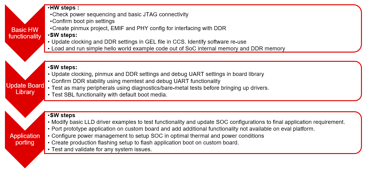
This section provides the guidelines for creating a custom board library.
Below image shows the recommended sequence to be followed while porting processor SDK to custom board.
3.1.3.1. Board Configurations
Board library supports different SoC and HW board specific configuration functions. Below table shows configurations supported by board library across different platforms.
| Board Configuration | Description | References | J721E | AM65xx | AM57xx | AM437x | AM335x | K2G | K2-E/H/K/L |
|---|---|---|---|---|---|---|---|---|---|
| Pinmux | Configures pinmux for interfaces on the HW board. | `Pinmux Tool`_ | x | x | x | x | x | x | |
| SoC Clock Settings | Enables power domains and clocks for SoC peripherals | Clock Tree Tool | x | x | x | x | x | x | x |
| DDR Configuration | Configures DDR/EMIF controller and DDR timing parameters. | EMIF Tools Appnote | x | x | x | x | x | ||
| PLL Configuration | Configures PLL modules to generate various clocks used by the SoC. | NA | x | x | x | x | x | ||
| Ethernet Configuration | Configures Ethernet PHYs on the board. | NA | x | x | x | x | x | x | |
| IO Instances | Defines IO instances for HW interfaces. | NA | x | x | x | x | x | x | x |
| Board Detection | EEPROM board ID for board detection. | NA | x | x | x | x | x | x | |
| Board Flash APIs | Provides Common APIs for accessing flash devices. | NA | x | x | x | x | x | x | |
| SerDes Configuration | Configures SerDes interface internal muxing and basic setup. | NA | x | x |
Adding custom board library can follow two approaches as mentioned below
3.1.3.2. Creating Board Configurations
Before updating the board library with configurations for custom board, it is recommended to use GEL file and CCS for validating the configurations. Follow the steps mentioned below
- Update the SoC clock configurations in the GEL file. TI provides Clock Tree Tool to simulate the device clocks.
- Update the PLL clock configurations in GEL file if custom board uses a different input clock than the eval platform and/or needs different clock outputs.
- Update DDR PHY and timing configurations for custom board. Refer the guidelines described in Application Report on EMIF Tools
- After GEL file update is complete, connect to custom board using JTAG, run the GEL script to apply the modified configurations and verify the configured values. Load and run simple hello world example out of SoC internal memory and DDR memory.
3.1.3.3. Updating Board Configurations
Steps for updating the board library configurations for a custom board is described in this section. Updating some of the configurations may need additional steps based on the platform. Refer Platform Specific Configuration section for more details.
3.1.3.3.1. Pinmux
When the BOARD_INIT_PINMUX_CONFIG option is specified, the Board_init() API configures the pinmux for the board. If applicable, it will also configure IO delay values for those device pads, which ensures correct IO timings are met along with the pinmux settings. Refer SOC TRM for additional details.
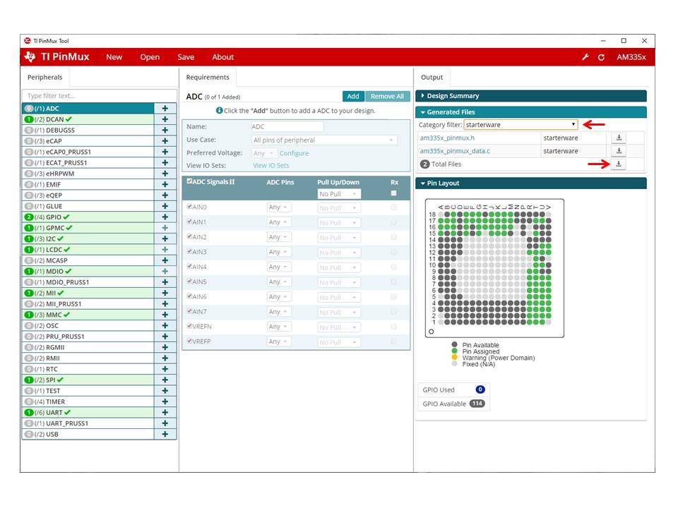
The pinmux data to be configured is generated by the TI pinmux tool. Refer to TI PinMux Tool for more information.
Once the pinmux selection is done, Copy the pinmux tool generated files to your custom board library implementation folder.
Refer Platform Specific Configuration section for more details on the files generated by pinmux tool for different platforms.
3.1.3.3.2. SoC Clock Settings
The core clocks and module clocks used on the custom board library may vary based on the power requirements and external components used on the boards.
<Board>_clock.c: Defines functions and structures for configuring the clock and power modules. Update this file based on the data from clock tree tool and GEL file validation.
3.1.3.3.3. DDR Configuration
The board library has the correct DDR initialization sequence to initialize the DDR memory on your board. You may need to make changes to the AC timings, hardware leveling, and DDR PHY configuration, some or all of which may be different than the TI supported platforms. GEL file can be used to verify the settings in CCS before modifying the source in the board library.
<Board>_ddr.c: Defines functions and structures for configuring the DDR module. Update this file based on the DDR timing parameters specific to custom board.
3.1.3.3.4. PLL Configuration
The SOC board library in the PDK configures the SOC PLL and module clock settings to the nominal settings required to be used with the TI evaluation platform. If you want to use different clock settings due to power consideration, or if you are using a variant of the device that needs to be clocked differently, you can enter the PLL and clock settings in the board library. All of the PLL and module clock settings are consolidated in the following files:
- <Board>.c: Contains calls related to all board-level initialization. <Board> refers to the evaluation platform (For example, evmam335x)
- <Board>_pll.c: Defines the Board_PLLInit() function that configures the dividers and multipliers for the clock tree.
3.1.3.3.5. Ethernet Configuration
The custom board may have external components (flash devices, Ethernet PHY, etc.) that are different from the components populated on the TI-supported EVM. These components and their support files need to be added to the pdk_xx_xx_xx_xx/packages/ti/board/src/<customBoardName>/device path and linked as part of the board library build.
3.1.3.3.6. IO Instances
If your custom board uses an IO instance different from the TI-supported board, the instance needs to be modified in the Pin Mux setup as well as in the board_cfg.h file in pdk_xx_xx_xx_xx/packages/ti/board/src/<customBoardName>/include
3.1.3.3.6.1. Board Detection
- TI defined board detect mechanism using structure stored in I2C EEPROM
- Board Lib APIs read and write Board ID to EEPROM on I2C address 0x50
- Application boards, if available, will have their own EEPROM with board information
- Structure typically defines:
Board ID (IDK vs GP EVM vs custom)
Revision number (board revision to address board level issues)
Serial Number (internal tracking)
MAC ID  (Custom MAC ID use)
Note
Board detection is TI defined mechanism to detect evaluation platform details. This needs to be removed/replicated from board based on customer board implementation. In case board detect mechanism is not used in custom board, check for the Board_getIDInfo() API calls and make necessary changes in the code to avoid dependencies on board detect mechanism.
3.1.3.3.6.2. Board Flash APIs
Board library includes a dedicated flash library to abstract the HW flash interface access using a standard set of APIs. In case custom board uses flash devices that are different from eval platform, update to board flash APIs is required. Check the board flash library available at <PDK_INSTALL_PATH>/packages/ti/board/src/flash and make changes required for custom board as needed.
3.1.3.4. Platform Specific Configurations
3.1.3.4.1. J721E
3.1.3.4.1.1. Board File Names
Board library file names for J721E are different when compared with other platforms in processor SDK. This is to facilitate the easy migration of board library to custom platforms. Read the file name <Board>.c as board_init.c and <Board>_xxx.c/h as board_xxx.c/h in all the references in above sections.
3.1.3.4.1.2. Pinmux
Follow below steps to update pinmux configuration for custom board on J721E platform. Pinmux project files provided under j721e_evm board folder can be used as reference for pinmux configuration.
Download the pinmux files <Platform Name>_pinmux.h and <Platform Name>_pinmux_data.c generated by pinmux tool and copy them to custom board folder.
Open ‘packages/ti/board/src/j721e_evm/<Platform Name>_pinmux.h’ and make below modifications.
- Change #include “pinmux.h” to #include <ti/board/src/j721e_evm/include/pinmux.h>
- Change #include “csl_types.h” to #include <ti/csl/csl_types.h> * Modify ‘j721e_evm’ in above step if a different name is used for custom board.
Tip
<Platform Name>_pinmux.h file contains the basic pin definition macros which will not change with every pin configuration change. This file generation and above step is one time configuration for a given pinmux tool version.
- Modify the Board_pinmuxConfig() function in ‘packages/ti/board/src/j721e_evm/board_pinmux.c’ file to remove pinmux configurations specific to EVM addon boards. Look for the comment “Pinmux for Application cards” in the function Board_pinmuxConfig(). All the code after this comment till end of the function and ‘i2cPinmux’ variable can be removed. Board_pinmuxConfig function shall look as below after the update
Board_STATUS Board_pinmuxConfig (void)
{
    Board_STATUS status = BOARD_SOK;

    /* Pinmux for baseboard */
    Board_pinmuxUpdate(gJ721E_MainPinmuxData,
                       BOARD_SOC_DOMAIN_MAIN);
    Board_pinmuxUpdate(gJ721E_WkupPinmuxData,
                       BOARD_SOC_DOMAIN_WKUP);

    return status;
}
- Rebuild the board library with new pinmux configurations
Follow additional steps (optional) below to clean-up the TI EVM addon board specific files.
Remove below files from SRCS_COMMON build configuration in ‘packages/ti/board/src/j721e_evm/src_files_j721e_evm.mk’ and remove the files from the board folder ‘packages/ti/board/src/j721e_evm’
- J721E_pinmux_data_gesi.c
- J721E_pinmux_data_gesi_cpsw9g.c
- J721E_pinmux_data_info.c
3.1.3.4.1.3. SerDes Configuration
J721E board library includes SerDes module which configures the SerDes interface internal pinmux to route PCIe, USB and SGMII to different interfaces on the board. If custom board uses similar design, SerDes configurations (board_serdes_cfg.c) can be reused. Otherwise this configuration can be ignored.
3.1.3.4.2. AM65xx
3.1.3.4.2.1. Pinmux
Follow below steps to update pinmux configuration for custom board on AM65xx platforms.
- Download the pinmux files <Platform Name>_pinmux.h and <Platform Name>_pinmux_data.c generated by pinmux tool
- Copy the files to custom board folder and rename them to match with board name if needed.
- Rebuild the board library with new pinmux configurations
3.1.3.4.2.2. SerDes Configuration
AM65xx board library includes SerDes module which configures the SerDes interface internal pinmux to route PCIe, USB and SGMII interfaces to different personality cards. If custom board uses similar design, SerDes configurations can be reused. Otherwise this configuration can be ignored.
3.1.3.4.3. AM57xx
3.1.3.4.3.1. Pinmux
Pinmux tool output for AM57xx platform includes IO delay information. Below are the files generated by pinmux tool:
- boardPadDelay.h: Includes the prototypes of all structures and functions used by pinmux functions
- boardPadDelayInit.c: Includes the pinmux pad config data for all device pads along with values used to compute Manual/Virtual mode values.This data is used to configure pinmux during board initialization.
- boardPadDelayTune.h: This file includes the compile time macros used to select the Timing modes to be configured for modules during board Initialization.
- boardPadDelayDevice.c: This file includes the pinmuxdata for runtime pinmux configuration of the MMC module.
Copy the above listed files generated by pinmux tool to custom board folder and rebuild the board library with updated pinmux configurations.
3.1.3.4.4. AM335x/AM437x
3.1.3.4.4.1. Pinmux
Follow below steps to update pinmux configuration for custom board on AM335x/AM437x platforms.
- Download the pinmux files <Platform Name>pinmux.h and <Platform Name>_pinmux_data.c generated by pinmux tool
- At the bottom of <Platform Name>pinmux.h change extern pinmuxBoardCfg_t g<Platform Name>PinmuxData[]; to extern pinmuxBoardCfg_t g<Custom Board Name>PinmuxData[];
- Change <Platform Name>_pinmux_data.c to <Platform Name>_<Custom Board Name>pinmux_data.c
- Change g<Platform Name>PinmuxData to g<Custom Board Name>PinmuxData at the end of the file in <Platform Name>_<Custom Board Name>pinmux_data.c
- The last step is to invoke the PinMuxModuleConfig in the file <BoardName>_pinmux.c that is found at <PDK_INSTALL_PATH>packagestiboardsrc<BoardName>. For Example to add three instances of UART in the pinmux setup, users can add :
/* UART */
 status = PINMUXModuleConfig(CHIPDB_MOD_ID_UART, 0U, NULL);
 status = PINMUXModuleConfig(CHIPDB_MOD_ID_UART, 1U, NULL);
 status = PINMUXModuleConfig(CHIPDB_MOD_ID_UART, 4U, NULL);
3.1.3.4.5. K2G
3.1.3.4.5.1. Pinmux
- Follow below steps to update pinmux configuration for custom board on K2G platforms.
- Download the pinmux files <Platform Name>pinmux.h and <Platform Name>_pinmux_data.c generated by pinmux tool
- Copy the files to custom board folder and rename them to match with board name if needed.
- Rebuild the board library with new pinmux configurations
3.1.3.5. Custom Board Validation
Validate the basic functionality of custom board using hardware diagnostics before bringing-up RTOS applications or Linux. Hardware diagnostics help verify the functionality of on-board peripherals and external interfaces of each board.
Refer Board Diagnostics section for more details on the diagnostic tests supported as part of processor SDK.
Below are the recommended diagnostic tests which can be validated on custom board
- External memory (DDR): DDR timing and leveling setting can be checked out using mem_test
- Debug UART: Debug UART pin functionality
- Boot Media: Validate functionality of SD/MMC, OSPIor any other boot interfaces
- Board ID/EEPROM test: Recommend checking out/writing ID on personality EEPROM. This also checkout I2C pin functionality
- Ethernet PHY: Ethernet diagnostics tests read PHY configuration over MDIO and check for Link up status. Good first step before bringing up any network stack
3.1.3.6. Creating Board Library with Custom Name
This section describes how to create a board library with custom name using AM572x as an example. Due to dependencies on the starterware, AM335x/AM437x board library creation is different and is described in the section for AM335x/AM437x.
As mentioned in section Board Configurations, adding custom board library can follow one of two approaches. This section provides detailed instructions for the second approach - adding a custom board to PDK build.
3.1.3.6.1. Instructions to add custom Board to the PDK build
Follow below steps for creating board library with custom name. AM572x platform is used as reference in the examples wherever needed.
Step 1: Creating new directory for custom board library
In <PDK_INSTALL_PATH>/packages/ti/board/src, create new directory myCustomBoard and copy files from existing board library package which closely matches your custom board design.
Step 2: Updating names and makefile inside the customBoard package
In <PDK_INSTALL_PATH>/packages/ti/board/src/myCustomBoard, rename file src_files_<Board>.mk to src_files_myCustomBoard.mk. This file will need a bit of work depending on what elements of board you need for your platform. At a minimum, modify SRCDIR and INCDIR to have correct paths to the newly created directory in previous step:
SRCDIR += src/myCustomBoard src/myCustomBoard/device src/myCustomBoard/include
INCDIR += src/myCustomBoard src/myCustomBoard/device src/myCustomBoard/include
Step 3: Adding MACRO based inclusion of updated board_cfg.h corresponding to custom Board
In packages/ti/board/board_cfg.h, add the lines pointing to board_cfg.h file in your customBoard package so that updated peripheral instances and board specific defines can be picked up
#if defined (myCustomBoard)
#include <ti/board/src/myCustomBoard/include/board_cfg.h>
#endif
Step 4: Update top level board package makefile to include build for customBoard library
Modify makefile packages/ti/board/build/makefile.mk which includes all relevant makefiles for low level driver(LLD), source files relevant to board and the common board.c file.
- Add customBoard build for board.c and boardStub.c (notice the newly added myCustomBoard):
ifeq ($(BOARD),$(filter $(BOARD),evmAM335x icev2AM335x skAM335x bbbAM335x evmAM437x idkAM437x skAM437x myCustomBoard evmAM572x idkAM571x idkAM572x evmK2H evmK2K evmK2E evmK2L evmK2G iceK2G evmC6678 evmC6657))
# Common source files across all platforms and cores
SRCS_COMMON += board.c
endif

ifeq ($(BOARD),$(filter $(BOARD),evmAM335x icev2AM335x iceAMIC110 skAM335x bbbAM335x evmAM437x idkAM437x skAM437x myCustomBoard evmAM572x idkAM571x idkAM572x evmK2H evmK2K evmK2E evmK2L iceK2G evmC6678 evmC6657 evmOMAPL137 lcdkOMAPL138 idkAM574x evmDRA72x evmDRA75x evmDRA78x evmTDAxx j721e_sim j721e_qt j7200_evm tpr12_evm))
# Board stub function enabled for all the boards except evmK2G
SRCS_COMMON += boardStub.c
endif
- Add customBoard build for board library source files and LLD files:
ifeq ($(BOARD),$(filter $(BOARD), myCustomBoard evmAM572x idkAM571x idkAM572x))
include $(PDK_BOARD_COMP_PATH)/src/$(BOARD)/src_files_$(BOARD).mk
include $(PDK_BOARD_COMP_PATH)/src/src_files_lld.mk
endif
Step 5: Update Global makerules
Makefile packages/ti/build/makerules/build_config.mk defines the global CFLAGS used to compile different PDK components. Add the following line in the BOARD specific configurations:
CFLAGS_GLOBAL_myCustomBoard = -DSOC_AM572x -DmyCustomBoard=myCustomBoard
The SOC_AM572x macro ensures that the CSL applicable to this SOC will be included in the build. Use the SoC name that corresponds to the platform of your custom board.
Optional step to update RTSC platform definition If you have a custom RTSC platform definition for your custom board that updates the memory and platform configuration using RTSC Tool then you need to update the platform.mk file that associates the RTSC platform with the corresponding board library
In packages/ti/build/makerules/platform.mk, add the following lines:
ifeq ($(BOARD),$(filter $(BOARD), evmAM572x))
  PLATFORM_XDC = "ti.platforms.evmAM572X"
endif
ifeq ($(BOARD),$(filter $(BOARD), myCustomBoard))
  PLATFORM_XDC = "evmAM572XCustom"
endif
Note
The SYSBIOS platforms follow the convention to consolidate all platform definitions under SYSBIOS_INSTALL_PATH/packages/ti/platforms/* hence the convention ti.platorms.<platformName> but for custom platform, users are not required to follow this convention.
Step 6: Update source files corresponding to drivers used in board library
Makefile src_files_lld.mk file adds source files corresponding to LLD drivers used in the board library. Usually most boards utilize control driver like I2C (for programming the PMIC or reading EEPROM), UART drivers (for IO) and boot media drivers like (SPI/QSPI, MMC or NAND). In the example below, we assume that the custom Board library has dependency on I2C, SPI and UART LLD drivers. Since the LLD drivers will be linked to the application along with board library, board library only needs <driver>_soc.c corresponding to SOC used on the custom Board.
In packages/ti/board/src/src_files_lld.mk, add the following lines:
ifeq ($(BOARD),$(filter $(BOARD), myCustomBoard))
SRCDIR +=  $(PDK_INSTALL_PATH)/ti/drv/i2c/soc/am572x \
           $(PDK_INSTALL_PATH)/ti/drv/uart/soc/am572x \
           $(PDK_INSTALL_PATH)/ti/drv/spi/soc/am572x
INCDIR +=  $(PDK_INSTALL_PATH)/ti/drv/i2c/soc/am572x \
           $(PDK_INSTALL_PATH)/ti/drv/uart/soc/am572x \
           $(PDK_INSTALL_PATH)/ti/drv/spi/soc/am572x
# Common source files across all platforms and cores
SRCS_COMMON += I2C_soc.c UART_soc.c SPI_soc.c
endif
Note
For all LLD drivers linked to the board library you need to include corresponding <drv>_soc.c file. For example if you include GPIO driver for setting board mux then GPIO_soc.c needs to be added to LLD source files.
Step 7: Add custom Board to BOARDLIST and update CORELIST
In packages/ti/board/board_component.mk, modify the build to add your custom board and specify the cores for which you want to build the board library. Example to build board library for only A15 and C66x cores, limit the build by specify only a15_0 and C66x in the CORELIST
board_lib_BOARDLIST = myCustomBoard evmAM335x icev2AM335x skAM335x bbbAM335x evmAM437x idkAM437x skAM437x evmAM572x idkAM571x idkAM572x evmK2H evmK2K evmK2E evmK2L evmK2G iceK2G \
#board_lib_am572x_CORELIST = c66x a15_0 ipu1_0
board_lib_am572x_CORELIST = a15_0 c66x
Step 8: Update .bld files for XDCTOOL based build steps
Make corresponding changes in packages/ti/board/config.bld, by adding the following lines:
var myCustomBoard = {
   name: "myCustomBoard",
   ccOpts: "-DmyCustomBoard -DSOC_AM572x",
   targets: [C66LE,A15LE ]
}
var boards = [ evmAM335x, icev2AM335x, skAM335x, bbbAM335x, evmAM437x, idkAM437x, skAM437x, myCustomBoard, evmAM572x, idkAM571x, idkAM572x, evmK2H, evmK2K, evmK2E, evmK2L, evmK2G, evmC6678, evmC6657 ];
Also, in packages/ti/board/package.bld, add the following line:
Pkg.otherFiles[Pkg.otherFiles.length++] = "src/myCustomBoard/src_files_myCustomBoard.mk";
Step 9: Add custom board to board list
Add myCustomBoard to AM572x board list in file packages/ti/build/soc_info.mk:
BOARD_LIST_am572x = evmAM572x idkAM572x myCustomBoard
Step 10: Build the custom board library with the updated settings
First change directory to <PDK_INSTALL_PATH>/packages and run pdksetupenv.bat.
Then change directory to <PDK_INSTALL_PATH>/packages/ti/board and build the board library:
gmake LIMIT_SOCS=am572x LIMIT_BOARDS=myCustomBoard LIMIT_CORES=a15_0
3.1.3.7. Creating Custom Board Library for AM335x and AM437x
This section describes how to create a custom board library for AM335x/AM437x. Currently the AM335x and AM437x board libraries reuse the board support code in legacy starterware (now part of the PDK). Therefore, rebuilding the board library involves compiling the starterware source code. Both approaches of creating a custom board library are described in this section:
- Modifying an existing TI board
- Adding a new custom board
3.1.3.7.1. Modifying an Existing TI Board for AM335x/AM437x
This approach is less time consuming since the board library setup already exists in PDK, but requires users to back up the existing TI board library for reference. The instructions below use AM335x GP EVM as the existing board to modify. Users may choose to modify any other existing board and the procedure is the same.
- Step 1: Generating a new pinmux configuration
- Download and run the PINMUX Tool.
- Use “Open an Existing Design” and open <PDK_INSTALL_PATH>/packages/ti/starterware/tools/pinmux_config/am335x/gpevm_config.pinmux.
- Use the tool to change the configuration and make sure there are no conflicts.
- When configuration is finalized, save the starterware pinmux files as shown below:
Step 2: Using newly generated pinmux files for the board to be modified
- Open am335x_pinmux.h saved in previous step and replace the following line at the bottom of the file
extern pinmuxBoardCfg_t gAM335xPinmuxData[];
with the following lines from <PDK_INSTALL_PATH>/packages/ti/starterware/board/am335x/am335x_pinmux.h:
/** \brief Pinmux configuration data for the board. Auto-generated from
           Pinmux tool. */
extern pinmuxBoardCfg_t gGpevmPinmuxData[];

/** \brief Pinmux configuration data for the board. Auto-generated from
           Pinmux tool. */
extern pinmuxBoardCfg_t gEvmskPinmuxData[];

/** \brief Pinmux configuration data for the board. Auto-generated from
           Pinmux tool. */
extern pinmuxBoardCfg_t gBbPinmuxData[];

/** \brief Pinmux configuration data for the board. Auto-generated from
           Pinmux tool. */
extern pinmuxBoardCfg_t gBbbPinmuxData[];

/** \brief Pinmux configuration data for the board. Auto-generated from
           Pinmux tool. */
extern pinmuxBoardCfg_t gIceV1PinmuxData[];

/** \brief Pinmux configuration data for the board. Auto-generated from
           Pinmux tool. */
extern pinmuxBoardCfg_t gIceV2PinmuxData[];

/** \brief Pinmux configuration data for the board. Auto-generated from
           Pinmux tool for IceV2, but with AMIC11x naming. Intended for
           manual deviation from IceV2, if applicable. */
extern pinmuxBoardCfg_t gAMIC11xPinmuxData[];
- Rename am335x_pinmux_data.c saved in previous step to am335x_gpevm_pinmux_data.c.
Then replace the following line toward the end of this file
pinmuxBoardCfg_t gAM335xPinmuxData[] =
with
pinmuxBoardCfg_t gGpevmPinmuxData[] =
- Replace am335x_pinmux.h and am335x_gpevm_pinmux_data.c in folder
<PDK_INSTALL_PATH>/packages/ti/starterware/board/am335x with the two files newly generated and modified above. It is recommended to keep a copy of this folder as a reference before replacing the two files.
Step 3: Updating board library files accordingly
- Update pinmux configuration in <PDK_INSTALL_PATH>/packages/ti/board/src/evmAM335x_pinmux.c. For example, to add another UART instance, the following line can be added to function Board_pinmuxConfig():
status = PINMUXModuleConfig(CHIPDB_MOD_ID_UART, 1U, NULL);
- Update power and clocking in <PDK_INSTALL_PATH>/packages/ti/board/src/evmAM335x.c. For example, to enable power and clocking for the second UART instance, the following line can be added to function Board_moduleClockInit():
status = PRCMModuleEnable(CHIPDB_MOD_ID_UART, 1U, 0U);
- Update LLD initialization if necessary in <PDK_INSTALL_PATH>/packages/ti/board/src/evmAM335x_lld_init.c. For example, to initialize the second UART, following line can be added to function Board_uartStdioInit():
UART_stdioInit(1);
Step 4: Rebuilding board library for the modified board
- Setup build environment:
C:\ti\pdk_am335x_1_0_17\packages>pdksetupenv.bat
- Rebuild board library:
C:\ti\pdk_am335x_1_0_17\packages\ti\board>gmake LIMIT_SOCS=am335x LIMIT_BOARDS=evmAM335x
Step 5: Rebuilding the boot loader
After the board library is rebuilt, the application can be built against the new board library. If the secondary boot loader is used to initialize the board, the boot loader will also need to be rebuilt according to section Building AM335x/AM437x Bootloader.
For example, issue following command under <PDK_INSTALL_PATH>/packages/ti/starterware to build MMCSD boot loader for AM335x:
gmake bootloader BUILDCFG=boot BOOTMODE=mmcsd PLATFORM=am335x-evm PROFILE=release -s KW_BUILD=no
3.1.3.7.2. Adding a New Custom Board for AM335x/AM437x
For this approach, due to the board library’s dependencies on starterware for AM335x/AM437x, additional steps are needed on top of what’s described in section Board Library Creation with Custom Name. Please follow all the steps given in that section to setup the custom board, and do the following before building the custom board library:
- First, make sure “var myCustomBoard” is added to packages/ti/board/config.bld and it includes all custom starterware files, especially the pinmux data source file. For example,
var myCustomBoard = {
    name: "myCustomBoard",
    ccOpts: "-DmyCustomBoard -DSOC_AM335X -DAM335X_FAMILY_BUILD -Dam335x -DBUILDCFG_MOD_UART -DBUILDCFG_MOD_GPIO  -DBUILDCFG_MOD_I2C  -DBUILDCFG_MOD_MCSPI  -DBUILDCFG_MOD_QSPI -DBUILDCFG_MOD_PRU_ETH -DBUILDCFG_MOD_MMCSD  -DBUILDCFG_MOD_CPSW -DBUILDCFG_MOD_PWMSS -DBUILDCFG_MOD_DSS -DBUILDCFG_MOD_USB -DBUILDCFG_MOD_GPMC -DBUILDCFG_MOD_DCAN -DBUILDCFG_MOD_MCASP -DBUILDCFG_MOD_VPFE -DBUILDCFG_MOD_MDIO -DBUILDCFG_MOD_DMTIMER -DBUILDCFG_MOD_EDMA3CC -DBUILDCFG_MOD_EDMA3TC -DBUILDCFG_MOD_RTC -DBUILDCFG_MOD_WDT -DBUILDCFG_MOD_ADC -DBUILDCFG_MOD_LCDC",
    stwFiles: ["$(PDK_INSTALL_PATH)/ti/starterware/board/am335x/am335x_myCustomBoard_pinmux_data.c",
            ...
}
- Second, in packages/ti/board/src/src_files_starterware.mk, add custom board build option and add custom pinmux data source file. For example,
ifeq ($(BOARD),$(filter $(BOARD), evmAM335x icev2AM335x iceAMIC110 skAM335x bbbAM335x myCustomBoard))
             ...

    ifeq ($(BOARD),$(filter $(BOARD), myCustomBoard))
        SRCS_COMMON += am335x_myCustomBoard_pinmux_data.c
    endif
3.2. Diagnostics
3.2.1. Overview
The Processor SDK RTOS Diagnostic package is designed to be a set of baremetal tests to run on a given board to provide data path continuity testing on peripherals. For K2H/K2E/K2L/C66x devices, this functionality is provided by POST.
3.2.2. Building the Examples
3.2.2.1. Pre-requisites to Building
- Set your environment using pdksetupenv.bat or pdksetupenv.sh. The diagnostic application uses the same environment variables as the board library build. Refer to the Processor SDK RTOS Building page for information on setting up your build environment.
- You will need the following libraries built:
- Board
- UART
- GPIO
- I2C
- SPI
- CSL
- ICSS
- PRUSS
- MMCSD
- EMAC
- USB
- UDMA
- SCICLIENT
(Note: not every library is used for every application, and these libraries should come pre-built with any fresh installation of the Processor SDK)
3.2.2.2. Compiling the Diagnostic Applications
To build the diagnostic examples:
- cd <PDK>/packages/ti/board/diag
- make <BOARD>
This will make the diagnostic applications for a specific $BOARD. Output files will be located in: <PDK>/packages/ti/board/bin/<BOARD>
3.2.2.3. Creating the SD Card Loadable Files
For converting the compiled .out files to a format loadable by TI’s Secondary Boot Loader (SBL), you must follow these two steps:
- out2rprc.exe [.out file] [rprc output]
- MulticoreImageGen.exe LE 55 [output name] 0 [rprc output]
Out2rprc.exe and MulticoreImageGen.exe are tools supplied by TI and can be located in the <PDK>/packages/ti/boot/sbl/tools folder. “rprc output” can be any spare name of your choosing. “output name” can also be any name of your choosing. For diagnostic applications, your final output name must have the keyword “TEST” in it. You will have to do this process for every .out application you wish to be loadable on the SD card.
Alternatively, there is also a make target to automate this process:
- cd <PDK>/packages/ti/board/diag
- make <BOARD>_sd
This will compile all the applications for a specific $BOARD, and also create the SD card loadable files. The output files will be located in: <PDK>/packages/ti/board/bin/<BOARD>/sd. Note that the framework application is named “app” to allow it to be the default application to be loaded by the SBL.
Note
Diagnostic tests on AM65xx platform supports A53 and R5 cores. A53 binary path: <PDK>/packages/ti/board/bin/<BOARD>/sd/armv8. R5 binary path: <PDK>/packages/ti/board/bin/<BOARD>/sd/armv7.
3.2.2.4. Creating the SPI Flash Loadable Files
SPI boot shall be the primary boot option for the platforms (Ex: AMIC110 ICE) which does not support SD card interface. All the diagnostic tests are integrated into framework binary for the ease of use in the case of SPI boot. Integrated diagnostic framework test binary can be loaded and executed through UART port.
Use below command to build the diagnostic tests and create SPI flash loadable files.
- make <BOARD>_spi
3.2.2.5. Make targets
The simplest invocation is to use “make <BOARD>” to compile all the applications. Here is a list of make targets implemented for the diagnostic makefile:
- make <BOARD> - compile all diagnostic applications for one specific BOARD
- make clean - clean and remove all applications for all supported BOARDs
- make <BOARD>_clean - clean and remove all application for one specific BOARD
- make <BOARD>_sd - compile all diagnostic applications for one specific BOARD and create the SD card loadable files with those compiled applications
- make <BOARD>_spi - compile all diagnostic applications for one specific BOARD and create the SPI flash loadable files with those compiled applications
The <BOARD> supported depends on your Processor SDK RTOS variant. Refer to following table for available <BOARD> for each Processor SDK RTOS variant:
| make target / Variant | am335x | am437x | am57xx | k2g | omapl13x | AM65xx |
|---|---|---|---|---|---|---|
| <Board> | evmAM335x skAM335x bbbAM335x icev2AM33 5x iceAMIC11 0 | evmAM437x skAM437x idkAM437x | idkAM572x idkAM571x evmAM572x idkAM574x | evmK2G iceK2G | evmOMAPL1 37 (No Boot support. Diagnosti cs need to run from CCS) |
am65xx_evm am65xx_idk (Supports A53 & R5 cores) |
Note
OMAPL137 EVM diagnostic tests does not support executing from a boot device. Use the command make evmOMAPL137 to build the diagnostics. Diagnostics test binaries need to be executed from CCS.
3.2.3. Running the Diagnostic Examples
3.2.3.1. Loading through SD Card (Default Method)
Your SD card must be set up to a bootable format. Refer to the Processor SDK RTOS Boot page for information on how the SD card is handled.
You will need to compile the diagnostic applications for your BOARD, created their respective SD card loadable files, and copied them onto an SD card. You will also need the SBL (renamed to “MLO”) on the SD card. To do so:
- cd <PDK>/packages/ti/board/diag
- make <BOARD>_sd
- copy all the content under <PDK>/packages/ti/board/bin/<BOARD>/sd to your SD card
- copy the MLO to your SD card (default location at <PDK>/packages/ti/boot/sbl/binary/<BOARD>/mmcsd
- insert your SD card into your board and power on your board
- open Terminal emulator program eg: Teraterm to connect to the board’s UART console
Note
Use MAIN UART0 console for running the tests on A53 core and MCU UART console for running the tests on R5 core for AM65xx platform.
- press the “Hard Reset” button on your board. (This is to force re-booting, and not absolutely necessary. Because Terminal emulator program is opened after boot is powered on, you would’ve missed the initial printout messages. This step is for demonstration and confidence checking that the board has booted correctly)
Note
Diagnostic tests on AM65xx platform supports A53 and R5 cores. A53 binary path: <PDK>/packages/ti/board/bin/<BOARD>/sd/armv8. R5 binary path: <PDK>/packages/ti/board/bin/<BOARD>/sd/armv7.
Note
SBL binary name is different on AM65xx platform and requires system firmware binary also to be copied to SD card. Copy the sbl_mmcsd_img_mcu1_0_release.tiimage file from <PDK>/packages/ti/boot/sbl/binary/mmcsd/<BOARD> to SD card and rename it to tiboot3.bin. Copy the system firmware image <PDK>/packages/ti/drv/sciclient/soc/V0/sysfw.bin to SD card
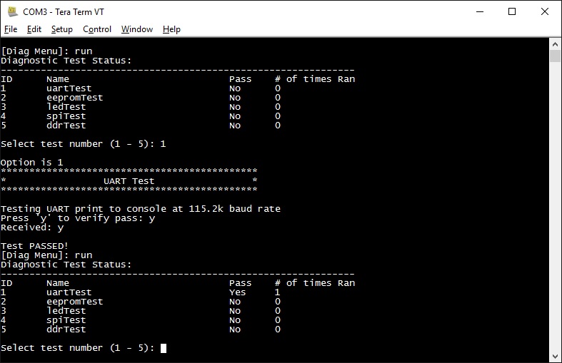
You should see the following screen when board is bootted with diagnostic binaries in SD card:
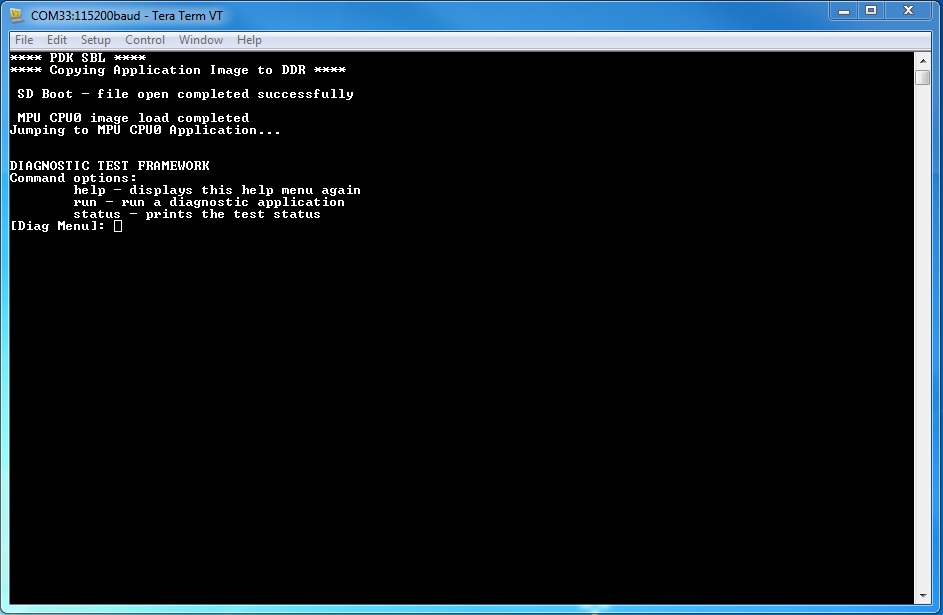
The framework diagnostic application should be loaded through SBL, and gives you the options:
- help - prints the command menu and descriptions of the commands
- run - run a diagnostic application found on the SD card
- status - current status of the framework run
Below is an example of running a diagnostic application:
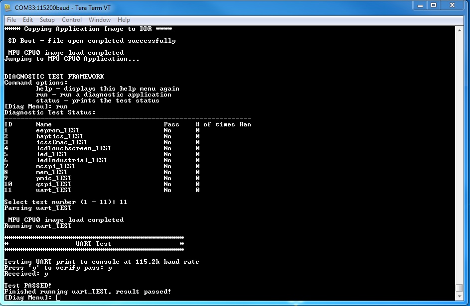
Result of return from above run:
3.2.3.2. Loading through SPI Flash
This section describes creating the diagnostic test images for SPI flash booting, programming and running them from SPI flash. Currently SPI boot is supported only by iceAMIC110 platform.
You will need to compile the diagnostic applications for your BOARD, create their respective SPI flash loadable files, and program them onto SPI flash. To do so:
- cd <PDK>/packages/ti/board/diag
- make <BOARD>_spi
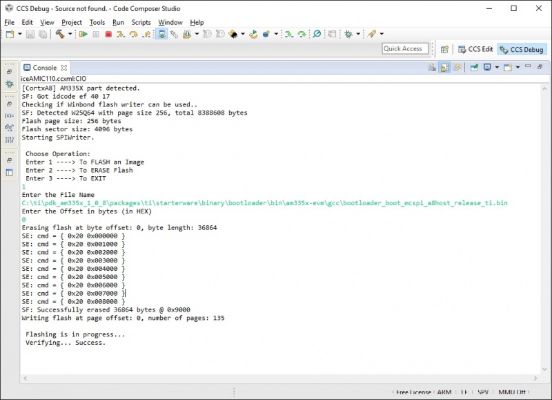
- Start CCS and launch target configuration file for AMIC110 ICE board
- Connect the target, load and run the SPI flash writer binary. Prebuilt SPI flash writer is available at <AM335x PDK>packagestistarterwaretoolsflash_writerspi_flash_writer_AM335X.out
- Choose option 1 to initiate image flashing
- Enter the file name as SPI bootloader along with full path (Ex: <AM335x PDK>packagestistarterwarebinarybootloaderbinam335x-evmgccbootloader_boot_mcspi_a8host_release_ti.bin)
- Enter offset as 0
- Wait until flashing completes successfully
- Rerun the SPI flash writer binary and program diagnostic framework loader at offset 20000. Diagnostic framework loader binary will be available at <AM335x PDK>packagestiboardbiniceAMIC110spiapp
- Rerun the SPI flash writer binary and program diagnostic framework at offset 40000. Diagnostic framework binary will be available at <AM335x PDK>packagestiboardbiniceAMIC110spiframework
Sample CCS output of SPI flash writer is shown below:
- open Terminal emulator program eg: Teraterm to connect to the board’s UART console
- press the “Hard Reset” button on your board. (This is to force re-booting, and not absolutely necessary. Because Terminal emulator program is opened after boot is powered on, you would’ve missed the initial printout messages. This step is for demonstration and confidence checking that the board has booted correctly)
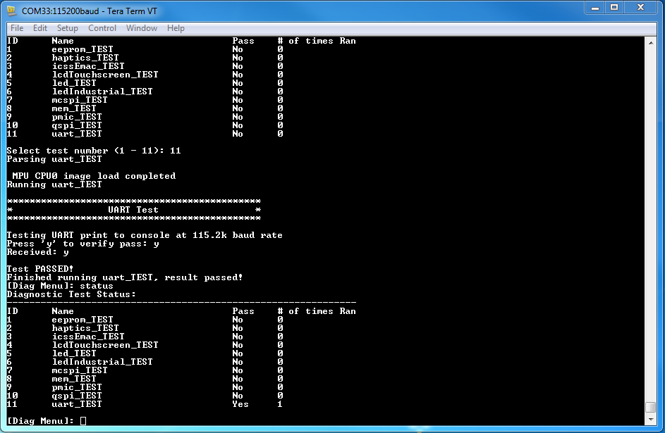
You should see the following screen:
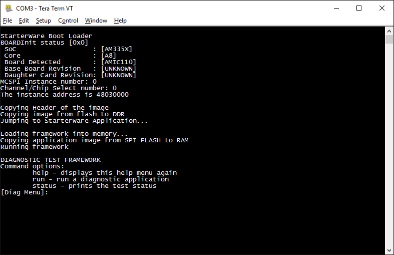
- help - prints the command menu and descriptions of the commands
- run - run a diagnostic application found on the SD card
- status - current status of the framework run
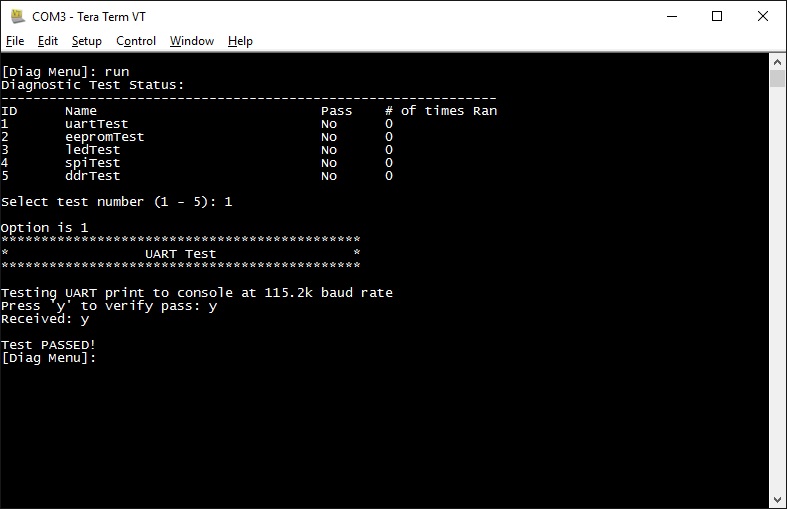
Below is an example of running a diagnostic application:
3.2.3.3. Running or debugging on CCS
To debug your application, CCS can give you access to the chip’s memory and register values. You can follow the below steps to load and run an application in CCS. If you have a SD card loadable image, and is able to load your application, you can connect to the A15 core in CCS and load symbols without having to load and run the entire application. After running “make all” or “make $BOARD”, the output files should be generated under <PDK>/packages/ti/board/bin/ directory. You will have to navigate down to the $BOARD you’re building (eg. idkAM572x, evmAM572x, etc.) and the $TARGET core you’re building for (eg. armv7).
For the existing diagnostic applications, you may need to define PDK_RAW_BOOT before compiling. This is done by adding the line “#define PDK_RAW_BOOT” to an individual application source file or to <PDK>/packages/ti/board/src/<BOARD>/include/board_cfg.h to apply for all applications. This is used because the default diagnostic loading method is through SD card, and the pinmux is done already. Adding this option only forces the diagnostic applications to do pinmuxing within the application itself (and not depend it being done).
To run on CCS:
- Connect USB cable to the board’s JTAG
- Connect the UART serial cable. For the IDK boards, the UART console is the same as the usb JTAG connector, so no additional cable is necessary.
- Plug in power cord to your board
- Press the power button on the board to turn the board on
- Setup and run CCSv6.1 (or higher). Follow the Processor SDK RTOS Getting Started Guide on how to setup your CCS to connect to the board
- Launch target configuration for the board
- Connect to the core that you built your application for. For example: for idkAM572x armv7 projects, click on the Cortex A-15 MPU0 core and press the connect button
- Load the program by pressing the load button and navigate the explorer to the .out file that you want to load
- Press the Run button to run the program
- Check UART console to see if anything is printed out. **If nothing is printed out, pause the core and see where the program counter is at. If it is at 0x3808c (or near it), try reloading the program and running again.
Note
Diagnostics are built for both DSP (C674x) and ARM (arm9) cores on omapl13x platform.
3.2.3.4. Running on a different ARM core
The diagnostic baremetal applications are typically targeted for Core 0 of an ARM corepac. It is possible to load and run it on one of the subcores in CCS. To do so, please consider the following:
- Enable Cache - setup typically only enables cache for the main ARM core. You may have to explicitly enable the data and instruction cache. See relevant cache functions under pdk/packages/ti/csl/arch.
- [For AM57x boards] Set OPP to high - SBL would set OPP to high for Core 0, but may not do it for the subcores. You can do so by using the GEL file. After connecting to the core, run the function under Scripts -> AM572x PRCM CLOCK configuration -> AM572x_PRCM_Clock_Config_OPPHIGH (similarly named for AM571x).
3.2.4. Diagnostic Applications
| Name | Description | AM65xx EVM | AM65xx IDK | GP AM572x | IDK AM572x/AM574x | IDK AM571x | EVM K2G | ICE K2G | EVM AM335x | SK AM335x | BBB AM335x | ICEv2 AM335x | EVM AM437x | SK AM437x | IDK AM437x | EVM OMAPL137 | ICE AMIC110 |
|---|---|---|---|---|---|---|---|---|---|---|---|---|---|---|---|---|---|
| lcdTouchscreen_TEST | Test for device detection and read the X, Y and Z axis values to confirm values within range. | x | x | x | x | ||||||||||||
| adc_TEST | Test for ADC configuration for Channel sequencing and One shot mode operation. | x | x | x | x | ||||||||||||
| ambient_TEST | Test for device detection on board and working of the light sensor. | x | x | ||||||||||||||
| buzzer_TEST | Writes to GPIO in connected to a buzzer. Requires user to verify sound | x | x | ||||||||||||||
| clock_TEST | Probes the clock generator on I2C bus | x | |||||||||||||||
| currentMonitor_TEST | Read voltage, current on I2C devices | x | x | x | |||||||||||||
| currentMonitorStress_TEST | Read voltage, current on I2C devices. Test is repeated for 100 cycles. Press ‘b’ to stop the test before completing test cycles. | x | x | ||||||||||||||
| dcan_TEST | Does DCAN loopback writes and reads. Passes on successful return. | x | x | x | |||||||||||||
| eeprom_TEST | Reads the EEPROM and prints out the board’s ID information. Passes on successful I2C reads. EEPROM will need to be programmed prior in order for a correct read. | x | x | x | x | x | x | x | x | x | x | x | x | x | x | x | |
| emac_TEST | Sends packet o PHY loopback t verify MAC operations | x | x | x | |||||||||||||
| emacStress_TEST | Verifies EMAC Ethernet ports by sending and receiving 10240 packets. | x | x | ||||||||||||||
| emmc_TEST | Writes to and read from eMMC memory. Passes on reading back the correct value as the one written | x | x | x | x | x | x | ||||||||||
| emmcStress_TEST | Writes to and read from eMMC memory. Test covers the entire eMMC memory | x | x | ||||||||||||||
| app | The main diagnostic application. This is loaded by SBL and can load other diagnostic applications on the SD card. | x | x | x | x | x | x | x | x | x | x | x | x | x | x | x | |
| gmac_TEST | Sends and receive packets over ethernet, both internally and externally. Passes on receiving all packets. | x | x | ||||||||||||||
| haptics_TEST | Writes to the GPIO pin connected to a motor (haptics). Requires user to verify that the motor is active. | x | x | x | |||||||||||||
| hdmi_TEST | Tests HDMI display output | x | |||||||||||||||
| icssEmac_TEST | Configures one ICSS EMAC port and tests functionality via packet loopback. | x | x | ||||||||||||||
| lcd_TEST | Tests LCD display output and touch input | x | x | ||||||||||||||
| lcdTouchscreen_TEST | Prompts the user for touches on the LCD touchscreen and report back its location. Requires user to input 9 simultaneous touches to verify pass. | x | x | ||||||||||||||
| led_TEST | Cycles through GPIO LEDs on the board. Requires user to verify the LEDs blink. | x | x | x | x | x | x | x | x | x | x | x | x | x | x | x | |
| ledStress_TEST | Cycles through GPIO LEDs on the board. Requires user to verify the LEDs blink. Test is repeated for 100 cycles. Press ‘b’ to stop the test before completing test cycles. | x | x | ||||||||||||||
| ledIndustrial_TEST | Cycles through the I2C LEDs on the board. Requires user to verify LEDs blink. | x | x | x | x | x | |||||||||||
| ledIndustrialStress_TEST | Cycles through the I2C LEDs on the board. Requires user to verify LEDs blink. Test is repeated for 100 cycles. Press ‘b’ to stop the test before completing test cycles. | x | x | ||||||||||||||
| mcspi_TEST | Attempts one write and read on the MCSPI header. Requires user to verify the value being read back is as expected. | x | x | x | x | ||||||||||||
| mem_TEST | Writes and reads to external (DDR) memory of the board. Value written/read is the address of the word. This is done two times, for value and ~value (complement), to test for all bits. | x | x | x | x | x | x | x | x | x | x | x | x | x | x | x | |
| memStress_TEST | Writes and reads to external (DDR) memory of the board. Walking 1’s and walking 0’s tests are executed on the whole DDR memory | x | x | ||||||||||||||
| mmcsd_TEST | Writes to and read from MMCSD memory. Passes on reading back the correct value as the one written | x | x | x | x | x | x | x | x | x | x | x | x | ||||
| mmcsdStress_TEST | Writes to and read from MMCSD memory. Passes on reading back the correct value as the one written. Entire SD card memory starting from 1.5GB offset is written/read during the test. | x | x | ||||||||||||||
| nand_TEST | Tests reading and writing to NAND flash memory | x | |||||||||||||||
| norflash_TEST | Tests reading and writing to NOR flash memory | x | x | x | |||||||||||||
| norflashStress_TEST | Tests reading and writing to NOR flash memory. Entire NOR flash memory is accessed during the test. | x | x | ||||||||||||||
| oled_TEST | Light up the OLED display to verify functionality | x | |||||||||||||||
| pmic_TEST | Writes and reads to the PMIC controller. This is to verify ability to use I2C to control PMIC. Test passes on successful read and write. | x | x | x | x | x | x | x | x | x | |||||||
| qspi_TEST | Tests the Quad SPI by writing and reading back the value written to memory. Test passes on correct data read back. | x | x | x | x | x | |||||||||||
| rotarySwitch_TEST | Tests the rotary switch at the 10 possible positions | x | x | ||||||||||||||
| rtc_TEST | Test for setting date and time to RTC registers and running the clock | x | x | x | x | x | x | x | |||||||||
| temperature_TEST | Tests reading back from temperature sensor via I2C. Test passes on successful I2C reads. | x | x | x | x | x | x | ||||||||||
| temperatureStress_TEST | Tests reading back from temperature sensor via I2C. Test passes on successful I2C reads. Test is repeated for 100 cycles. Press ‘b’ to stop the test before completing test cycles. | x | x | ||||||||||||||
| uart2usb_TEST | Tests uart messages over usb port. | x | |||||||||||||||
| uart_TEST | Data Path continuity test for UART output. Requires user to verify that outputs do appear on console. | x | x | x | x | x | x | x | x | x | x | x | x | x | x | ||
| uartStress_TEST | Verifies UART port with large block of data transfer. Sends 10MB of data from the board to serial console. Teraterm script loops the data back to the board. Data recieved on the board and verified. RS485 to RS232 coverter is needed to run the test on AM65xx platform. Need to run this test from CCS. SD boot support is not available. |
x | x | ||||||||||||||
| mcasp_TEST | On-board audio codec functionality is exercised by this test. Audio supplied at EVM audio input port will loopback to audio output port. This test is intended to demonstrate baremetal functionality of mcasp, edma3 and i2c CSL modules without depending on the LLD libraries. No console output is supported by this test. | x | x | ||||||||||||||
| mcaspAudioDC_TEST | Multi-channel audio daughter card functionality is exercised by this test. Audio supplied at audio DC input ports will loopback to audio DC output ports. This test is intended to demonstrate bare metal functionality of mcasp, edma3 and spi CSL modules without depending on the LLD libraries. No console output is supported by this test. | x | |||||||||||||||
| pwm_TEST | Demonstrates the usage of PWM CSL FL APIs by configuring the PWM module to generate a pulse of 1KHz with different duty cycle - 25, 50 and 75%. | x | x | x | x | ||||||||||||
| usbDevice_TEST | Verifies the USB device mode operation of board under test. USB modules operates at high speed (2.0) Board is exposed as USB MSC device to host PC during the test. | x | x | ||||||||||||||
| usbHost_TEST | Verifies the USB host mode operation of boardf under test. USB modules operates at high speed (2.0) during the test. File write/read and data verification on the connected USB device is done during the test | x | x | ||||||||||||||
| usbHostStress_TEST | Verifies the USB host mode operation of boardf under test. USB modules operates at high speed (2.0) during the test. File write/read and data verification on the connected USB device is done during the test Test is repeated for 100 cycles. Press ‘b’ to stop the test before completing test cycles. | x | x | ||||||||||||||
| ospi_TEST | Tests the Octal SPI by writing and reading back the value written to memory. Test passes on correct data read back. | x | x | ||||||||||||||
| ospiStress_TEST | Tests the Octal SPI by writing and reading back the value written to memory. Test passes on correct data read back. Entire OSPI flash memory is accessed during the test. | x | x | ||||||||||||||
| pcie_TEST | Tests the PCIe interface in end point and rootcomplex mode using two boards. Data is sent from one board to other and sent it back to the first board for verification. | x | x | ||||||||||||||
| bootEeprom_TEST | Verifies boot EEPROM by writing a block of data, reading back written data for correctness. | x | x | ||||||||||||||
| bootEepromStress_TEST | Verifies boot EEPROM read/write covering entire memory. | x | x | ||||||||||||||
| extRtc_TEST | Test for setting date and time to external RTC and running the clock | x | x | ||||||||||||||
| extRtcStress_TEST | Test for setting date and time to external RTC and running the clock. Test is repeated for 100 cycles. Press ‘b’ to stop the test before completing test cycles. | x | x | ||||||||||||||
| icssgEmac_TEST | Verifies ICSSG EMAC ports in loopback with one port connected to another port. 10 packets are sent and received during the test. | x | x | ||||||||||||||
| icssgEmacStress_TEST | Verifies ICSSG EMAC ports in loopback with one port connected to another port. 10240 packets are sent and received during the test. | x | x | ||||||||||||||
| icssgLed_TEST | Cycles through LEDs on the IDK application board. | x | |||||||||||||||
| icssgLedStress_TEST | Cycles through LEDs on the IDK application board. Test is repeated for 100 cycles. Press ‘b’ to stop the test before completing test cycles. | x | |||||||||||||||
| bootSwitch_TEST | Verifies boot mode switch by configuring boot strap pins as GPIOs and reading the pin state with boot switch set in different patterns | x | x | ||||||||||||||
| button_TEST | Verifies push buttons on the board. Test prompts for pressing a specific button which will be detected by the test. | x | x | ||||||||||||||
| mcan_TEST | Verifies MCAN ports on the board with two ports connected with each other. Data is sent from one port and received on another port. Both ports are veirified for Tx and Rx | x | |||||||||||||||
| mcanStress_TEST | Verifies MCAN ports on the board with two ports connected with each other. 10240 packets are sent from one port and received on another port. Both ports are veirified for Tx and Rx | x | |||||||||||||||
| rs485_TEST | Verifies PRU UART port on the board. Supports board to board test and single board test. RS485 to RS232 coverter is needed to run the test on AM65xx platform | x | x | x | |||||||||||||
| rs485Stress_TEST | Verifies PRU UART port on the board. Sends 10MB of data from the board to serial console. Teraterm script loops the data back to the board. Data recieved on the board and verified. RS485 to RS232 coverter is needed to run the test on AM65xx platform. Need to run this test from CCS. SD boot support is not available. |
x | |||||||||||||||
| Power On Self Test | Verifies basic memory devices on the board and displays the board ID details. Executed on boot automatically before displaying diag main menu. Can be skipped by entering ‘b’ in the serial console within 5 secs of diag boot. | x | x |
3.2.5. Additional Jumper or Hardware Settings
3.2.5.1. Current Monitor
For iceK2G, this test expects J16 and J17 to be connected with jumper shunts. This enables the current monitors to be used.
3.2.5.2. GMAC
For idkAM572x, idkAM571x, idkAM574x and evmAM572x, this test expects loopback plugs to be used on both Ethernet ports. These loopback plugs will loopback the TX lines back to the RX lines. The Ethernet ports are the RJ-45 connectors labeled “Ethernet” on the board.
3.2.5.3. ICSS EMAC
For idkAM572x, idkAM574x and idkAM571x, this test expects loopback plug to be used on J6. These loopback plugs will loopback the TX lines back to the RX lines. For iceK2G, this test expects loopback plugs to be used on all four ICSS EMAC ports.
3.2.5.4. LCD Touchscreen
For idkAM572x, idkAM574x and idkAM571x, this test expects the LCD module to be connected. This requires the two ribbon cables (one for display, one for the capacitive-touch IC) to be connected.
3.2.5.5. McSPI
For idkAM572x, idkAM574x and idkAM571x, this test expects pins to be connected to the Industrial I/O header. The Industrial I/O header, J37, has two columns in parallel, one of which is the McSPI input and the other being VDD. Thus, connecting any row with a jumper will yield a ‘1’ read on that McSPI input. By connecting the first, second, third, and forth row with jumpers would yield 0x1, 0x2, 0x4, and 0x8 being read respectively.
3.2.5.6. PWM
PWM output generated while running the diagnostic test can be verified at below pins.
evmK2G - J12 pin 33
evmAM572x - P17 pin 5
idkAM437x - J16 pin 14
evmAM335x - J5 pin 13
3.3. Diagnostics Execution
3.3.1. Overview
Detailed test procedure and additional HW setup needed for running the processor SDK board diagnostic tests are explained in the following sections. Logs shown for each test are for sample reference, actual logs may slightly vary from platform to platform.
Two different modes of diagnostic tests are supported - Functional and Stress. Functional tests verify basic functionality of an interface to confirm the interface HW connectivity. Stress tests verify the functionality of an interface under stress conditions which will confirm the stability of the HW interface.
Refer to Diagnostic Applications section for details of the platforms supported by each of the diagnostic tests described below.
Application/Daughter cards required for running the test are not mentioned in the test setup assuming the tests are run with full HW kit.
3.3.2. Functional Tests
This section describes the test procedure and setup for diagnostic functional tests.
3.3.2.1. Accelerometer Test
This test verifies the Accelerometer sensor on the HW platform under test.
3.3.2.1.1. Test Accessories
No additional accessories are required for running this test.
3.3.2.1.2. Test Setup
No specific test setup is needed. Use the default HW setup recommended in HW user manual.
3.3.2.1.3. Test Execution
- Select the menu option to run ‘accelerometer_TEST’
- Verify the test log on serial console
3.3.2.1.4. Test Log
Sample log for Accelerometer test is shown below
*********************************************
*         Accelerometer Test                *
*********************************************

Test:                Expected Result:    Actual Result:    Result:
----------------     ----------------    --------------    -------
0x32                 PASS
Self-Test(X Axis)    120-550             247               PASS
Self-Test(Y axis)    120-550             192               PASS
Self-Test(Z Axis)    140-750             349               PASS
Exiting
3.3.2.2. ADC Test
This test verifies ADC interface on the HW platform under test.
3.3.2.2.1. Test Accessories
No additional accessories are required for running this test.
3.3.2.2.2. Test Setup
No specific test setup is needed. Use the default HW setup recommended in HW user manual.
3.3.2.2.3. Test Execution
- Select the menu option to run ‘adc_TEST’
- Verify the test log on serial console
3.3.2.2.4. Test Log
Sample log for ADC test is shown below
*********************************************
*                 ADC Test                  *
*********************************************

Voltage sensed on the AN0 line : 846mV
Voltage sensed on the AN1 line : 1156mv

Test PASSED!
3.3.2.3. Boot EEPROM Test
This test verifies Boot EEPROM memory. First and last page of the EEPROM are written with a test pattern and read back for data verification.
3.3.2.3.1. Test Accessories
No additional accessories are required for running this test.
3.3.2.3.2. Test Setup
Make sure pins 2-3 of J44 and J45 headers on AM65x CP board are shorted
3.3.2.3.3. Test Execution
- Select the menu option to run ‘bootEeprom_TEST’
- Verify the test log on serial console
3.3.2.3.4. Test Log
Sample log for boot EEPROM test is shown below
*********************************************
*              Boot EEPROM Test             *
*********************************************

Running Boot EEPROM test

Detecting the Boot EEPROM device...

Boot EEPROM device detection successful

Boot EEPROM boundary verification test...

Verifying the Boot EEPROM first page...

Verifying the Boot EEPROM last page...

Boot EEPROM boundary verification test successful

Boot EEPROM test Passed
3.3.2.4. Boot Switch Test
Test verifies boot mode switch by configuring boot strap pins as GPIOs and reading the pin state with boot switch set in different patterns. Test prompts to set the boot switch with a specific pattern and waits for user confirmation of the setting. ON-OFF-ON... sequence indicated by the test starts from switch position 1.
3.3.2.4.1. Test Accessories
No additional accessories are required for running this test.
3.3.2.4.2. Test Setup
No specific test setup is needed. Use the default HW setup recommended in HW user manual.
3.3.2.4.3. Test Execution
- Select the menu option to run ‘bootSwitch_TEST’
- Setup the boot switch as instructed by the serial console log
- Verify the test log on serial console
3.3.2.4.4. Test Log
Sample log for boot switch test is shown below
*********************************************
*             Boot Switch Test              *
*********************************************
Set All switches to OFF
Press Enter after setting the switches

Set the Switches to ON-OFF-ON-OFF...
Press Enter after setting the switches

Set the Switches to OFF-ON-OFF-ON...
Press Enter after setting the switches

Set All switches to ON
Press Enter after setting the switches

Test Passed
3.3.2.5. Button Test
Verifies push buttons on the board. Test prompts for pressing a specific button which should be detected by the test and displayed on the console.
3.3.2.5.1. Test Accessories
No additional accessories are required for running this test.
3.3.2.5.2. Test Setup
No specific test setup is needed. Use the default HW setup recommended in HW user manual.
3.3.2.5.3. Test Execution
- Select the menu option to run ‘button_TEST’
- Press the button as instructed by the test messages on the serial console.
- Verify the test log on serial console. Make sure the button press is detected properly.
Note
Button release detection is supported only on AM65xx platform.
3.3.2.5.4. Test Log
Sample log for push button test is shown below
*********************************************
*                 Button Test               *
*********************************************

Running button test...
Button SW  5            WAIT      Waiting for button press Button Pressed
Button SW  5            WAIT      Waiting for button release Button released
Button SW  5            PASS
Button SW  6            WAIT      Waiting for button press Button Pressed
Button SW  6            WAIT      Waiting for button release Button released
Button SW  6            PASS
Test PASSED!
3.3.2.6. Buzzer Test
This test verifies the Buzzer interface on the HW platform under test.
3.3.2.6.1. Test Accessories
No additional accessories are required for running this test.
3.3.2.6.2. Test Setup
No specific test setup is needed. Use the default HW setup recommended in HW user manual.
3.3.2.6.3. Test Execution
- Select the menu option to run ‘buzzer_TEST’
- Verify the Buzzer sound on the HW platform
- Verify the test log on serial console
- Press ‘y’ to confirm proper buzzer output or any other key to indicate failure
3.3.2.6.4. Test Log
Sample log for buzzer test is shown below
*********************************************
*               Buzzer Test                *
*********************************************

Testing Buzzer sound
Press 'y' to verify pass: y
Received: y

Test PASSED!
3.3.2.7. Clock Generator Test
This test verifies clock generator interface on the HW platform under test. Need to probe and confirm the clocks during the test.
3.3.2.7.1. Test Accessories
Oscilloscope to verify the clock outputs
3.3.2.7.2. Test Setup
No specific test setup is needed. Use the default HW setup recommended in HW user manual.
3.3.2.7.3. Test Execution
- Select the menu option to run ‘clock_TEST’
- Verify the test log on serial console
- Verify the clock generator output clocks and confirm the result on the serial console
3.3.2.7.4. Test Log
Sample log for clock generator test is shown below
**********************************
       CLOCK GENERATOR Test
**********************************

Running Clock generator Detect Test

Clock generator Detection Successful!

Clock generator Detect Test Passed!


Running Clock generator probe Test

Probe the clock generator clock outputs
Are the signals generated properly ?
Press 'Y' to confirm, any other key to deny
y

Clock generator probe Test Passed!

Clock generator Test Passed!

Clock generator Tests Completed!!

-----------------X-----------------
3.3.2.8. Current Monitor Test
Test reads the voltage and current values from different current monitor devices available on the board. All the current monitor devices available on the board are verified during the test.
3.3.2.8.1. Test Accessories
No additional accessories are required for running this test.
3.3.2.8.2. Test Setup
For iceK2G, this test expects J16 and J17 to be connected with jumper shunts. This enables the current monitors to be used.
3.3.2.8.3. Test Execution
- Select the menu option to run ‘currentMonitor_TEST’
- Verify the test log on serial console
3.3.2.8.4. Test Log
Sample log for current monitor test is shown below
**********************************************
*            Current Monitor Test            *
**********************************************

Running Current Monitor Test...

Verifying Device VDD_CORE at Address - 0x40
Setting the configuration register...
Setting the calibration register...
Calibration Value = 16777
Reading the Shunt Voltage register...
Shunt Voltage Register Value = 9
Shunt Voltage = 0mV
Reading the Bus Voltage register...
Bus Voltage Register Value = 800
Bus Voltage = 1000mV
Reading the Power register...
Power Register Value = 3
Power = 915mW
Reading the Current register...
Current Register Value = 74
Current = 11mA


Verifying Device VDD_MCU at Address - 0x41
Setting the configuration register...
Setting the calibration register...
Calibration Value = 16777
Reading the Shunt Voltage register...
Shunt Voltage Register Value = 1534
Shunt Voltage = 3mV
Reading the Bus Voltage register...
Bus Voltage Register Value = 797
Bus Voltage = 996mV
Reading the Power register...
Power Register Value = 501
Power = 19108mW
Reading the Current register...
Current Register Value = 12566
Current = 383mA


Verifying Device VDD_MPU at Address - 0x42
Setting the configuration register...
Setting the calibration register...
Calibration Value = 27962
Reading the Shunt Voltage register...
Shunt Voltage Register Value = 6
Shunt Voltage = 0mV
Reading the Bus Voltage register...
Bus Voltage Register Value = 802
Bus Voltage = 1002mV
Reading the Power register...
Power Register Value = 3
Power = 503mW
Reading the Current register...
Current Register Value = 82
Current = 7mA


Verifying Device SoC_DVDD3V3 at Address - 0x43
Setting the configuration register...
Setting the calibration register...
Calibration Value = 27962
Reading the Shunt Voltage register...
Shunt Voltage Register Value = 15
Shunt Voltage = 0mV
Reading the Bus Voltage register...
Bus Voltage Register Value = 2665
Bus Voltage = 3331mV
Reading the Power register...
Power Register Value = 28
Power = 2670mW
Reading the Current register...
Current Register Value = 205
Current = 18mA


Verifying Device SoC_DVDD1V8 at Address - 0x44
Setting the configuration register...
Setting the calibration register...
Calibration Value = 5592
Reading the Shunt Voltage register...
Shunt Voltage Register Value = 108
Shunt Voltage = 0mV
Reading the Bus Voltage register...
Bus Voltage Register Value = 1442
Bus Voltage = 1802mV
Reading the Power register...
Power Register Value = 21
Power = 3204mW
Reading the Current register...
Current Register Value = 295
Current = 26mA


Verifying Device SoC_AVDD1V8 at Address - 0x45
Setting the configuration register...
Setting the calibration register...
Calibration Value = 41943
Reading the Shunt Voltage register...
Shunt Voltage Register Value = 1196
Shunt Voltage = 2mV
Reading the Bus Voltage register...
Bus Voltage Register Value = 1442
Bus Voltage = 1802mV
Reading the Power register...
Power Register Value = 387
Power = 14760mW
Reading the Current register...
Current Register Value = 5358
Current = 65mA


Verifying Device SoC_VDDS_DDR at Address - 0x46
Setting the configuration register...
Setting the calibration register...
Calibration Value = 8388
Reading the Shunt Voltage register...
Shunt Voltage Register Value = 256
Shunt Voltage = 0mV
Reading the Bus Voltage register...
Bus Voltage Register Value = 956
Bus Voltage = 1195mV
Reading the Power register...
Power Register Value = 50
Power = 1335mW
Reading the Current register...
Current Register Value = 1049
Current = 63mA


Verifying Device VDD_DDR at Address - 0x47
Setting the configuration register...
Setting the calibration register...
Calibration Value = 8388
Reading the Shunt Voltage register...
Shunt Voltage Register Value = 38
Shunt Voltage = 0mV
Reading the Bus Voltage register...
Bus Voltage Register Value = 957
Bus Voltage = 1196mV
Reading the Power register...
Power Register Value = 8
Power = 689mW
Reading the Current register...
Current Register Value = 156
Current = 9mA
3.3.2.9. DCAN Test
This test verifies the DCAN ports on the HW platform under test. Test supports verifying the DCAN interface in internal and external loopback modes.
3.3.2.9.1. Test Accessories
DCAN loopback cable (for evmK2G)
3.3.2.9.2. Test Setup
Connect two DCAN ports (P2 and P3) with DCAN loopback cable - only on evmK2G
3.3.2.9.3. Test Execution
- Select the menu option to run ‘dcan_TEST’
- Follow the instructions on serial console to select the DCAN instance
- Verify the test log on serial console
3.3.2.9.4. Test Log
Sample log for DCAN test is shown below
*********************************************
*                 DCAN Test                 *
*********************************************


**** DCAN APPLICATION TEST ****
Menu:
1. DCAN External Loopback test - DCAN1 Instance
2. DCAN Internal Loopback test - DCAN2 Instance
x. Exit
Select DCAN APPLICATION TEST : 1

DCAN External Loopback Test App: DCAN1 MSG OBJ 1 (TX) to DCAN1 MSG OBJ 2 (RX)

DCAN -- External Loopback Testmode test Passed!!


**** DCAN APPLICATION TEST ****
Menu:
1. DCAN External Loopback test - DCAN1 Instance
2. DCAN Internal Loopback test - DCAN2 Instance
x. Exit
Select DCAN APPLICATION TEST : 2

DCAN Internal Loopback Test App: DCAN2 MSG OBJ 1 (TX) to DCAN2 MSG OBJ 2 (RX)

DCAN -- Internal Loopback Testmode test Passed!!


**** DCAN APPLICATION TEST ****
Menu:
1. DCAN External Loopback test - DCAN1 Instance
2. DCAN Internal Loopback test - DCAN2 Instance
x. Exit
Select DCAN APPLICATION TEST : x

DCAN Application Test exiting...
3.3.2.10. EEPROM Test
This test reads and displays the board ID details from the EEPROM memory.
3.3.2.10.1. Test Accessories
No additional accessories are required for running this test.
3.3.2.10.2. Test Setup
No specific test setup is needed. Use the default HW setup recommended in HW user manual.
3.3.2.10.3. Test Execution
- Select the menu option to run ‘eeprom_TEST’
- Verify the board ID details displayed on the serial console
3.3.2.10.4. Test Log
Sample log for Board ID EEPROM test is shown below
*********************************************
*              EEPROM Test                  *
*********************************************
header: aa5533ee
boardName: 66AK2GICE
version: 1.0A
serialNum: 09164P540001
Test PASSED!
Note
Board ID content shown in the above log changes from platform to platform.
3.3.2.11. EMAC Test
This test verifies the EMAC Ethernet port on HW platform under test. Ethernet link and data transmit/receive are verified during this test. Ethernet interface is configured for 100mbps speed and 10 packets are sent/received during the test. Ethernet cable disconnect/reconnect and data transfer after cable connection is also verified during the test.
3.3.2.11.1. Test Accessories
Ethernet loopback cables/plugs
3.3.2.11.2. Test Setup
Connect the Ethernet loopback cables to the EMAC Ethernet port (RJ-45) on the board. Check below table for the details of EMAC Ethernet ports used by the test on different platforms.
| HW Platform | Ethernet Port |
|---|---|
| iceK2G | J10 |
| am65xx_evm | J12 on CP board |
| am65xx_idk | J12 on CP board |
3.3.2.11.3. Test Execution
- Select the menu option to run ‘emac_TEST’
- Follow the instructions on serial console for disconnecting and connecting the cable during the test.
- Verify the test log on serial console
3.3.2.11.4. Test Log
Sample log for Ethernet loopback test is shown below
************************************************
*             ETHERNET LOOPBACK Test           *
************************************************

Reading Ethernet PHY Register Dump...
Register Dump for PHY Addr - 0x0000
PHY Register 0x0000 - 0x1140
PHY Register 0x0001 - 0x7949
PHY Register 0x0002 - 0x2000
PHY Register 0x0003 - 0xa231
PHY Register 0x0004 - 0x01e1
PHY Register 0x0005 - 0xc1e1
PHY Register 0x0006 - 0x006f
PHY Register 0x0007 - 0x2001
PHY Register 0x0008 - 0x4806
PHY Register 0x0009 - 0x0300
PHY Register 0x000a - 0x8c00
PHY Register 0x000b - 0x0000
PHY Register 0x000c - 0x0000
PHY Register 0x000d - 0x401f
PHY Register 0x000e - 0x0006
PHY Register 0x000f - 0x3000
PHY Register(STRAP1) 0x006e - 0x0000
PHY Register(STRAP2) 0x006f - 0x0000
RGMII Control Register (RGMIICTL) Value - 0x00d3
  --- RGMII_RX_CLK_DELAY - 0x0001
  --- RGMII_TX_CLK_DELAY - 0x0001
RGMII Delay Control Register (RGMIIDCTL) Value - 0x0077
EMAC loopback test application initialization
main: emac_open success
Configuring Phy
Waiting for Link Status
Link is UP!!

Sending Packet: 1
Sending Packet: 2
Sending Packet: 3
Sending Packet: 4
Sending Packet: 5
Sending Packet: 6
Sending Packet: 7
Sending Packet: 8
Sending Packet: 9
Sending Packet: 10
Received Packet: 1
Received Packet: 2
Received Packet: 3
Received Packet: 4
Received Packet: 5
Received Packet: 6
Received Packet: 7
Received Packet: 8
Received Packet: 9
Received Packet: 10

Packets sent: 10, Packets received: 10

Ethernet Loopback test passed
All tests completed
Please disconnect the loopback cable
Link is Down
Please reconnect the loopback cable
Link is UP

Reading Ethernet PHY Register Dump...
Register Dump for PHY Addr - 0x0000
PHY Register 0x0000 - 0x1000
PHY Register 0x0001 - 0x796d
PHY Register 0x0002 - 0x2000
PHY Register 0x0003 - 0xa231
PHY Register 0x0004 - 0x01e1
PHY Register 0x0005 - 0xc1e1
PHY Register 0x0006 - 0x006f
PHY Register 0x0007 - 0x2001
PHY Register 0x0008 - 0x4006
PHY Register 0x0009 - 0x1000
PHY Register 0x000a - 0x0000
PHY Register 0x000b - 0x0000
PHY Register 0x000c - 0x0000
PHY Register 0x000d - 0x401f
PHY Register 0x000e - 0x0006
PHY Register 0x000f - 0x3000
PHY Register(STRAP1) 0x006e - 0x0000
PHY Register(STRAP2) 0x006f - 0x0000
RGMII Control Register (RGMIICTL) Value - 0x00d3
  --- RGMII_RX_CLK_DELAY - 0x0001
  --- RGMII_TX_CLK_DELAY - 0x0001
RGMII Delay Control Register (RGMIIDCTL) Value - 0x0077
EMAC loopback test application initialization
main: emac_open success
Configuring Phy
Waiting for Link Status
Link is UP!!

Sending Packet: 1
Sending Packet: 2
Sending Packet: 3
Sending Packet: 4
Sending Packet: 5
Sending Packet: 6
Sending Packet: 7
Sending Packet: 8
Sending Packet: 9
Sending Packet: 10
Received Packet: 1
Received Packet: 2
Received Packet: 3
Received Packet: 4
Received Packet: 5
Received Packet: 6
Received Packet: 7
Received Packet: 8
Received Packet: 9
Received Packet: 10

Packets sent: 10, Packets received: 10

Ethernet Loopback test passed
All tests completed
3.3.2.12. eMMC Test
This test verifies eMMC memory interface on the HW platform under test. 16KB of data is written and read during the test.
3.3.2.12.1. Test Accessories
No additional accessories are required for running this test.
3.3.2.12.2. Test Setup
No specific test setup is needed. Use the default HW setup recommended in HW user manual.
3.3.2.12.3. Test Execution
- Select the menu option to run ‘emmc_TEST’
- Verify the test log on serial console
3.3.2.12.4. Test Log
Sample log for eMMC test is shown below
*********************************************
*                 eMMC Test                 *
*********************************************

PASS: Read/Write Success for this pattern
3.3.2.13. External RTC Test
This test verifies setting the time, date and running the clock for on-board RTC interface. RTC configuration is done through I2C interface. Time and date are read for 5 times for every 5secs during the test to demonstrate operation of the RTC clock.
3.3.2.13.1. Test Accessories
No additional accessories are required for running this test.
3.3.2.13.2. Test Setup
No specific test setup is needed. Use the default HW setup recommended in HW user manual.
3.3.2.13.3. Test Execution
- Select the menu option to run ‘extRtc_TEST’
- Verify the test log on serial console
- Confirm the test result by pressing ‘y’ if RTC time/date changes properly or press any key for failure
3.3.2.13.4. Test Log
Sample log for external RTC test is shown below
*********************************************
*                 RTC Test                  *
*********************************************

Setting Time...

Setting Date...

Reading Time...

Reading Date...


Displaying time: 11:59:53 PM
Displaying  Day: Sunday
Displaying Date: 31/12/18

Displaying time: 11:59:57 PM
Displaying  Day: Sunday
Displaying Date: 31/12/18

Displaying time: 12:0:2 AM
Displaying  Day: Monday
Displaying Date: 1/1/19

Displaying time: 12:0:7 AM
Displaying  Day: Monday
Displaying Date: 1/1/19

Displaying time: 12:0:12 AM
Displaying  Day: Monday
Displaying Date: 1/1/19

Displaying time: 12:0:17 AM
Displaying  Day: Monday
Displaying Date: 1/1/19
If the time and date increment, press 'y' to indicate pass or any other character to indicate failure
y

RTC test passed...
3.3.2.14. GMAC Test
This test verifies the GMAC Ethernet ports of the HW platform under test.
3.3.2.14.1. Test Accessories
Ethernet loopback cables/plugs
3.3.2.14.2. Test Setup
Connect the Ethernet loopback cables to the GMAC Ethernet port (RJ-45) on the board. Check below table for the details of GMAC Ethernet ports used by the test on different platforms.
| HW Platform | Ethernet Port |
|---|---|
| idkAM571x | J10 & J12 |
| idkAM572x | J10 & J12 |
| idkAM574x | J10 & J12 |
| evmAM572x | Both ports of P5 |
3.3.2.14.3. Test Execution
- Select the menu option to run ‘gmac_TEST’
- Verify the test log on serial console
3.3.2.14.4. Test Log
Sample log for GMAC test is shown below
*********************************************
*                 GMAC Test                 *
*********************************************
Test                    Port    Link    Link-Speed              Status    Error
--------------------    ----    ----    --------------------    ------    ---------------------------
Phy Loopback               1    Up    Phy Loopback            PASS
10Mbps Full-Duplex         1    Up    10Mbps Full duplex      PASS
100Mbps Half-Duplex        1    Up    100Mbps Half duplex     PASS
100Mbps Full-Duplex        1    Up    100Mbps Full duplex     PASS
Phy Loopback               2    Up    Phy Loopback            PASS
10Mbps Full-Duplex         2    Up    10Mbps Full duplex      PASS
100Mbps Half-Duplex        2    Up    100Mbps Half duplex     PASS
100Mbps Full-Duplex        2    Up    100Mbps Full duplex     PASS
Exiting
3.3.2.15. Haptics Test
This verifies haptics motor using vibrations on the HW platform under test.
3.3.2.15.1. Test Accessories
No additional accessories are required for running this test.
3.3.2.15.2. Test Setup
No specific test setup is needed. Use the default HW setup recommended in HW user manual.
3.3.2.15.3. Test Execution
- Select the menu option to run ‘haptics_TEST’
- Verify the test log on serial console
- Check for the vibrations on the HW platform
3.3.2.15.4. Test Log
Sample log for Haptics test is shown below
*********************************************
*               Haptics Test                *
*********************************************

Testing Haptics (vibration)
Press 'y' to verify pass: y
Received: y

Test PASSED!
3.3.2.16. HDMI Test
This test verifies HDMI display port on the HW platform under test. Color bar and different colors are displayed on HDMI monitor during the test.
3.3.2.16.1. Test Accessories
- HDMI Display
- HDMI cable
3.3.2.16.2. Test Setup
Connect the HDMI Display to the HDMI port on the board. Check below table for the details of HDMI ports used by the test on different platforms.
| HW Platform | HDMI Port |
|---|---|
| evmK2G | J36 |
3.3.2.16.3. Test Execution
- Select the menu option to run ‘hdmi_TEST’
- Verify the color bar and different colors displayed on the HDMI Monitor.
- Verify the test log on serial console and confirm test result.
3.3.2.16.4. Test Log
Sample log for HDMI test is shown below
***********************
       HDMI Test
***********************
Running HDMI Device Detect Test
sil9022 HDMI Chip version = b0
HDMI Device Detect Test Passed

Displaying Colorbar... WAIT  Press 'y' if Colorbar is displayed, any other key for failure: y
Display Colorbar   - PASS
Displaying WHITE... WAIT  Press 'y' if WHITE is displayed, any other key for failure: y
Display WHITE - PASS
Displaying BLUE... WAIT  Press 'y' if BLUE is displayed, any other key for failure: y
Display BLUE - PASS
Displaying GREEN... WAIT  Press 'y' if GREEN is displayed, any other key for failure: y
Display GREEN - PASS
Displaying RED... WAIT  Press 'y' if RED is displayed, any other key for failure: y
Display RED - PASS
Displaying PURPLE... WAIT  Press 'y' if PURPLE is displayed, any other key for failure: y
Display PURPLE - PASS
Displaying PINK... WAIT  Press 'y' if PINK is displayed, any other key for failure: y
Display PINK - PASS
Displaying BLACK... WAIT  Press 'y' if BLACK is displayed, any other key for failure: y
Display BLACK - PASS
Displaying YELLOW... WAIT  Press 'y' if YELLOW is displayed, any other key for failure: y
Display YELLOW - PASS

HDMI Tests Completed!!

-----------------X-----------------
3.3.2.17. ICSS EMAC Test
This test verifies ICSS EMAC Ethernet port on HW platform under test. PRU-ICSS Ethernet ports are configured for 100mbps speed and 5 packets are sent/received during the test.
3.3.2.17.1. Test Accessories
Ethernet loopback cables/plugs
3.3.2.17.2. Test Setup
Connect the Ethernet loopback cables to the PRU-ICSS Ethernet ports (RJ-45) on the board. Check below table for the details of Ethernet ports used by the test on different platforms.
| HW Platform | ICSS Ethernet Port |
|---|---|
| idkAM571x | J6 |
| idkAM572x | J6 |
| idkAM574x | J6 |
| iceK2G | All ports of J8 & J9 |
3.3.2.17.3. Test Execution
- Select the menu option to run ‘icssEmac_TEST’
- Verify the test log on serial console
3.3.2.17.4. Test Log
Sample log for ICSS EMAC test is shown below
PRU_ICSS0 Loopback Test
Waiting for LINK UP, Make sure to plugin loopback cable
PRU_ICSS0 port 0 LINK IS UP
PRU_ICSS0 port 1 LINK IS UP

Sending Packets on Port 0
Sending Pkt 0
Received pkt: 0
Sending Pkt 1
Received pkt: 1
Sending Pkt 2
Received pkt: 2
Sending Pkt 3
Received pkt: 3
Sending Pkt 4
Received pkt: 4

Sending Packets on Port 1
Sending Pkt 0
Received pkt: 0
Sending Pkt 1
Received pkt: 1
Sending Pkt 2
Received pkt: 2
Sending Pkt 3
Received pkt: 3
Sending Pkt 4
Received pkt: 4
All tests have passed

PRU_ICSS0 Loopback Test Completed!


PRU_ICSS1 Loopback Test
Waiting for LINK UP, Make sure to plugin loopback cable
PRU_ICSS1 port 0 LINK IS UP
PRU_ICSS1 port 1 LINK IS UP

Sending Packets on Port 0
Sending Pkt 0
Received pkt: 0
Sending Pkt 1
Received pkt: 1
Sending Pkt 2
Received pkt: 2
Sending Pkt 3
Received pkt: 3
Sending Pkt 4
Received pkt: 4

Sending Packets on Port 1
Sending Pkt 0
Received pkt: 0
Sending Pkt 1
Received pkt: 1
Sending Pkt 2
Received pkt: 2
Sending Pkt 3
Received pkt: 3
Sending Pkt 4
Received pkt: 4
All tests have passed

PRU1_ICSS0 Loopback Test Completed!
3.3.2.18. ICSSG EMAC Test
This port to port Ethernet test verifies the PRU-ICSS gigabit Ethernet interface on the board under test. During the test, Ethernet interface is configured for 1000mbps speed with one port of an ICSS instance is connected to another port. 5 packets are sent from one port and received by another port. Both the ports are verified for transmit and receive. All the ICSSG EMAC ports available on the board verified during the test. Note that ICSSG EMAC Test can also run on a am65xx_idk with Interposer daughter card. For details of Interposer daughter card, please refer to Device Drivers
3.3.2.18.1. Test Accessories
Ethernet cables
3.3.2.18.2. Test Setup
Connect Ethernet cable between two ports of an PRU-ICSS instance. Make such connections on all the PRU-ICSS ports available Check below table for the detials of ICSSG Ethernet ports used by the test on different platforms
| HW Platform | ICSSG Ethernet Port |
|---|---|
| am65xx_evm | Two ports on J14 of CP board. |
| am65xx_idk | Two ports on J14 of CP board. Two ports on J1 of IDK board. Two ports on J3 of IDK board. |
| am65xx_idk with Interposer card | Two ports on J14 of CP board. Two ports on J3 of IDK board. |
3.3.2.18.3. Test Execution
- Select the menu option to run ‘icssgEmac_TEST’
- Verify the test log on serial console
3.3.2.18.4. Test Log
Sample log for ICSGG Ethernet test is shown below
***************************************
*           ICSSG EMAC TEST           *
***************************************


Reading Ethernet PHY Register Dump...


Register Dump for PHY Addr - 0x0000
PHY Register 0x0000 - 0x1140
PHY Register 0x0001 - 0x796d
PHY Register 0x0002 - 0x2000
PHY Register 0x0003 - 0xa231
PHY Register 0x0004 - 0x01e1
PHY Register 0x0005 - 0xc1e1
PHY Register 0x0006 - 0x006f
PHY Register 0x0007 - 0x2001
PHY Register 0x0008 - 0x4806
PHY Register 0x0009 - 0x0300
PHY Register 0x000a - 0x7c00
PHY Register 0x000b - 0x0000
PHY Register 0x000c - 0x0000
PHY Register 0x000d - 0x401f
PHY Register 0x000e - 0x0006
PHY Register 0x000f - 0x3000
PHY Register(STRAP1) 0x006e - 0x0000
PHY Register(STRAP2) 0x006f - 0x0000
RGMII Control Register (RGMIICTL) Value - 0x00d3
  --- RGMII_RX_CLK_DELAY - 0x0001
  --- RGMII_TX_CLK_DELAY - 0x0001
RGMII Delay Control Register (RGMIIDCTL) Value - 0x0077


Register Dump for PHY Addr - 0x0003
PHY Register 0x0000 - 0x1140
PHY Register 0x0001 - 0x796d
PHY Register 0x0002 - 0x2000
PHY Register 0x0003 - 0xa231
PHY Register 0x0004 - 0x01e1
PHY Register 0x0005 - 0xc1e1
PHY Register 0x0006 - 0x006f
PHY Register 0x0007 - 0x2001
PHY Register 0x0008 - 0x4806
PHY Register 0x0009 - 0x0300
PHY Register 0x000a - 0x3c00
PHY Register 0x000b - 0x0000
PHY Register 0x000c - 0x0000
PHY Register 0x000d - 0x401f
PHY Register 0x000e - 0x0006
PHY Register 0x000f - 0x3000
PHY Register(STRAP1) 0x006e - 0x0003
PHY Register(STRAP2) 0x006f - 0x0000
RGMII Control Register (RGMIICTL) Value - 0x00d3
  --- RGMII_RX_CLK_DELAY - 0x0001
  --- RGMII_TX_CLK_DELAY - 0x0001
RGMII Delay Control Register (RGMIIDCTL) Value - 0x0077


Register Dump for PHY Addr - 0x0000
PHY Register 0x0000 - 0x1140
PHY Register 0x0001 - 0x796d
PHY Register 0x0002 - 0x2000
PHY Register 0x0003 - 0xa231
PHY Register 0x0004 - 0x01e1
PHY Register 0x0005 - 0xc1e1
PHY Register 0x0006 - 0x006f
PHY Register 0x0007 - 0x2001
PHY Register 0x0008 - 0x4806
PHY Register 0x0009 - 0x0300
PHY Register 0x000a - 0x3c00
PHY Register 0x000b - 0x0000
PHY Register 0x000c - 0x0000
PHY Register 0x000d - 0x401f
PHY Register 0x000e - 0x0006
PHY Register 0x000f - 0x3000
PHY Register(STRAP1) 0x006e - 0x0000
PHY Register(STRAP2) 0x006f - 0x0000
RGMII Control Register (RGMIICTL) Value - 0x00d3
  --- RGMII_RX_CLK_DELAY - 0x0001
  --- RGMII_TX_CLK_DELAY - 0x0001
RGMII Delay Control Register (RGMIIDCTL) Value - 0x0077


Register Dump for PHY Addr - 0x0003
PHY Register 0x0000 - 0x1140
PHY Register 0x0001 - 0x796d
PHY Register 0x0002 - 0x2000
PHY Register 0x0003 - 0xa231
PHY Register 0x0004 - 0x01e1
PHY Register 0x0005 - 0xc1e1
PHY Register 0x0006 - 0x006f
PHY Register 0x0007 - 0x2001
PHY Register 0x0008 - 0x4806
PHY Register 0x0009 - 0x0300
PHY Register 0x000a - 0x7c00
PHY Register 0x000b - 0x0000
PHY Register 0x000c - 0x0000
PHY Register 0x000d - 0x401f
PHY Register 0x000e - 0x0006
PHY Register 0x000f - 0x3000
PHY Register(STRAP1) 0x006e - 0x0003
PHY Register(STRAP2) 0x006f - 0x0000
RGMII Control Register (RGMIICTL) Value - 0x00d3
  --- RGMII_RX_CLK_DELAY - 0x0001
  --- RGMII_TX_CLK_DELAY - 0x0001
RGMII Delay Control Register (RGMIIDCTL) Value - 0x0077


Register Dump for PHY Addr - 0x0000
PHY Register 0x0000 - 0x1140
PHY Register 0x0001 - 0x796d
PHY Register 0x0002 - 0x2000
PHY Register 0x0003 - 0xa231
PHY Register 0x0004 - 0x01e1
PHY Register 0x0005 - 0xc1e1
PHY Register 0x0006 - 0x006f
PHY Register 0x0007 - 0x2001
PHY Register 0x0008 - 0x4806
PHY Register 0x0009 - 0x0300
PHY Register 0x000a - 0x7c00
PHY Register 0x000b - 0x0000
PHY Register 0x000c - 0x0000
PHY Register 0x000d - 0x401f
PHY Register 0x000e - 0x0006
PHY Register 0x000f - 0x3000
PHY Register(STRAP1) 0x006e - 0x0000
PHY Register(STRAP2) 0x006f - 0x0000
RGMII Control Register (RGMIICTL) Value - 0x00d3
  --- RGMII_RX_CLK_DELAY - 0x0001
  --- RGMII_TX_CLK_DELAY - 0x0001
RGMII Delay Control Register (RGMIIDCTL) Value - 0x0077


Register Dump for PHY Addr - 0x0003
PHY Register 0x0000 - 0x1140
PHY Register 0x0001 - 0x796d
PHY Register 0x0002 - 0x2000
PHY Register 0x0003 - 0xa231
PHY Register 0x0004 - 0x01e1
PHY Register 0x0005 - 0xc1e1
PHY Register 0x0006 - 0x006f
PHY Register 0x0007 - 0x2001
PHY Register 0x0008 - 0x4806
PHY Register 0x0009 - 0x0300
PHY Register 0x000a - 0x3c00
PHY Register 0x000b - 0x0000
PHY Register 0x000c - 0x0000
PHY Register 0x000d - 0x401f
PHY Register 0x000e - 0x0006
PHY Register 0x000f - 0x3000
PHY Register(STRAP1) 0x006e - 0x0003
PHY Register(STRAP2) 0x006f - 0x0000
RGMII Control Register (RGMIICTL) Value - 0x00d3
  --- RGMII_RX_CLK_DELAY - 0x0001
  --- RGMII_TX_CLK_DELAY - 0x0001
RGMII Delay Control Register (RGMIIDCTL) Value - 0x0077
port 0:  FW is ready
Port 0:  FlowId 2
Port 0:  Config FW Complete
port 1:  FW is ready
Port 1:  FlowId 3
Port 1:  Config FW Complete
port 2:  FW is ready
Port 2:  FlowId 10
Port 2:  Config FW Complete
port 3:  FW is ready
Port 3:  FlowId 11
Port 3:  Config FW Complete
port 4:  FW is ready
Port 4:  FlowId 18
Port 4:  Config FW Complete
port 5:  FW is ready
Port 5:  FlowId 19
Port 5:  Config FW Complete

EMAC loopback test application initialization
main: emac_open success


Waiting for LINK UP, Make sure to plugin loopback cable
PRU_ICSS port 0 LINK IS UP!

EMAC loopback test application initialization
main: emac_open success


Waiting for LINK UP, Make sure to plugin loopback cable
PRU_ICSS port 1 LINK IS UP!

EMAC loopback test application initialization
main: emac_open success


Waiting for LINK UP, Make sure to plugin loopback cable
PRU_ICSS port 2 LINK IS UP!

EMAC loopback test application initialization
main: emac_open success


Waiting for LINK UP, Make sure to plugin loopback cable
PRU_ICSS port 3 LINK IS UP!

EMAC loopback test application initialization
main: emac_open success


Waiting for LINK UP, Make sure to plugin loopback cable
PRU_ICSS port 4 LINK IS UP!

EMAC loopback test application initialization
main: emac_open success


Waiting for LINK UP, Make sure to plugin loopback cable
PRU_ICSS port 5 LINK IS UP!


Sending Packets on Port - 0
Sending Packet: 1
Sending Packet: 2
Sending Packet: 3
Sending Packet: 4
Sending Packet: 5

Receiving Packets on Port - 1
Received Packet: 1
Received Packet: 2
Received Packet: 3
Received Packet: 4
Received Packet: 5

Packets Sent: 5, Packets Received: 5
Port 0 Send to Port 1 Receive Test Passed!


Sending Packets on Port - 1
Sending Packet: 1
Sending Packet: 2
Sending Packet: 3
Sending Packet: 4
Sending Packet: 5

Receiving Packets on Port - 0
Received Packet: 1
Received Packet: 2
Received Packet: 3
Received Packet: 4
Received Packet: 5

Packets Sent: 5, Packets Received: 5
Port 1 Send to Port 0 Receive Test Passed!


Sending Packets on Port - 2
Sending Packet: 1
Sending Packet: 2
Sending Packet: 3
Sending Packet: 4
Sending Packet: 5

Receiving Packets on Port - 3
Received Packet: 1
Received Packet: 2
Received Packet: 3
Received Packet: 4
Received Packet: 5

Packets Sent: 5, Packets Received: 5
Port 2 Send to Port 3 Receive Test Passed!


Sending Packets on Port - 3
Sending Packet: 1
Sending Packet: 2
Sending Packet: 3
Sending Packet: 4
Sending Packet: 5

Receiving Packets on Port - 2
Received Packet: 1
Received Packet: 2
Received Packet: 3
Received Packet: 4
Received Packet: 5

Packets Sent: 5, Packets Received: 5
Port 3 Send to Port 2 Receive Test Passed!


Sending Packets on Port - 4
Sending Packet: 1
Sending Packet: 2
Sending Packet: 3
Sending Packet: 4
Sending Packet: 5

Receiving Packets on Port - 5
Received Packet: 1
Received Packet: 2
Received Packet: 3
Received Packet: 4
Received Packet: 5

Packets Sent: 5, Packets Received: 5
Port 4 Send to Port 5 Receive Test Passed!


Sending Packets on Port - 5
Sending Packet: 1
Sending Packet: 2
Sending Packet: 3
Sending Packet: 4
Sending Packet: 5

Receiving Packets on Port - 4
Received Packet: 1
Received Packet: 2
Received Packet: 3
Received Packet: 4
Received Packet: 5

Packets Sent: 5, Packets Received: 5
Port 5 Send to Port 4 Receive Test Passed!


ICSSG Ethernet Port to Port Test Passed!
All Tests Completed
3.3.2.19. LCD Test
This test verifies LCD display on the HW platform under test. Displaying color bar, LCD backlight control and touch verification is done during the test.
3.3.2.19.1. Test Accessories
LCD Display
3.3.2.19.2. Test Setup
Connect the LCD Display to the HW platform under test.
3.3.2.19.3. Test Execution
- Select the menu option to run ‘lcd_TEST’
- Verify the color bar displayed on the LCD display.
- Verify that LCD backlight is getting changed during backlight control test
- Provide touch inputs during the touch interface test and confirm that positions are detected properly
- Verify the test log on serial console
Note
Touch interface test is not supported on all the platforms. Refer to LCD Touchscreen Test for touch interface test on other platforms.
3.3.2.19.4. Test Log
Sample log for LCD test is shown below
*********************************************
*              Display Test                 *
*********************************************

LCD Board detect successfully

Running LCD Display Test...
DSS application started...
LCD configured successfully
Overlay configuration done
Video Port configuration done
Display the colour bar with maximum brightness

LCD Display Test Successfully

Running LCD Backlight Test

Changing Backlight... WAIT, Check the LCD panel

Increasing the brightness by varying the
duty cycle percentage form 0 to 100...


Decreasing the brightness by varying the
duty cycle percentage form 100 to 0...
  Press 'y' if Brightness is Increasing & Decreasing, Any other key for failure: y
Change Backlight - PASS

Running LCD Touch Detect Test

Running the LCD touch detect test...

Reading the touch device details
Reading the product ID...
The prod Id read is - 928
Reading the firmware version...
The firmware version read is - `ABC
Clearing the buffer status register...


Waiting for user to provide 20 single point touches...
(x - 371, y - 497)
(x - 672, y - 284)
(x - 371, y - 497)
(x - 785, y - 620)
(x - 819, y - 334)
(x - 857, y - 449)
(x - 387, y - 495)
(x - 679, y - 314)
(x - 792, y - 644)
(x - 805, y - 428)
(x - 821, y - 379)
(x - 909, y - 570)
(x - 909, y - 570)
(x - 794, y - 697)
(x - 807, y - 718)
(x - 824, y - 747)
(x - 952, y - 648)
(x - 829, y - 753)
(x - 839, y - 754)
(x - 890, y - 442)
LCD touch detect test passed!
3.3.2.20. LCD Touchscreen Test
This test verifies the LCD Touchscreen on the HW platform under test.
3.3.2.20.1. Test Accessories
LCD Display
3.3.2.20.2. Test Setup
Connect the LCD Display to the HW platform under test.
3.3.2.20.3. Test Execution
- Select the menu option to run ‘lcdTouchscreen_TEST’
- Provide multiple touch points to verify multi-touch input detection
- Verify the test log on serial console
3.3.2.20.4. Test Log
Sample log for LCD Touchscreen test is shown below
*********************************************
*             Touchscreen Test              *
*********************************************
Input 9 touches to exit test
Touch   t1              t2              t3              t4              t5              t6              t7              t8              t9
1        343, 389       4095,4095       4095,4095       4095,4095       4095,4095       4095,4095       4095,4095       4095,4095       4095,4095
2        343, 389       4095,4095       4095,4095       4095,4095       4095,4095       4095,4095       4095,4095       4095,4095       4095,4095
3        343, 389       4095,4095       4095,4095       4095,4095       4095,4095       4095,4095       4095,4095       4095,4095       4095,4095
4        343, 389       4095,4095       4095,4095       4095,4095       4095,4095       4095,4095       4095,4095       4095,4095       4095,4095
5        343, 389       4095,4095       4095,4095       4095,4095       4095,4095       4095,4095       4095,4095       4095,4095       4095,4095
6        343, 389       4095,4095       4095,4095       4095,4095       4095,4095       4095,4095       4095,4095       4095,4095       4095,4095
7        426, 637       4095,4095       4095,4095       4095,4095       4095,4095       4095,4095       4095,4095       4095,4095       4095,4095
8        426, 637       4095,4095       4095,4095       4095,4095       4095,4095       4095,4095       4095,4095       4095,4095       4095,4095
9        426, 637       4095,4095       4095,4095       4095,4095       4095,4095       4095,4095       4095,4095       4095,4095       4095,4095
9        426, 637       4095,4095       4095,4095       4095,4095       4095,4095       4095,4095       4095,4095       4095,4095       4095,4095
3.3.2.21. ICSS LED Test
This test verifies LEDs connected to PRU-ICSS ports. All the LEDs are turned ON and OFF for 3 times during the test.
3.3.2.21.1. Test Accessories
No additional accessories are required for running this test.
3.3.2.21.2. Test Setup
No specific test setup is needed. Use the default HW setup recommended in HW user manual.
3.3.2.21.3. Test Execution
- Select the menu option to run ‘icssgLed_TEST’
- Confirm that all the PRU-ICSS LEDs on the board are toggling during the test
- Verify the test log on serial console
- Confirm the test result by pressing ‘y’ in case of success and any other key for failure
3.3.2.21.4. Test Log
Sample log for ICSS LED test is shown below
*********************************************
*              ICSS LED Test                *
*********************************************

Testing ICSSG PRG0 and PRG1 LED's
Blinking LEDs...
Press 'y' to verify pass, 'r' to blink again,
or any other character to indicate failure: y
Received: y

Test PASSED!
3.3.2.22. Industrial LED Test
This test verifies industrial LEDs connected to I2C interface on the HW platform under test. All the LEDs are turned ON and OFF for 3 times during the test.
3.3.2.22.1. Test Accessories
No additional accessories are required for running this test.
3.3.2.22.2. Test Setup
No specific test setup is needed. Use the default HW setup recommended in HW user manual.
3.3.2.22.3. Test Execution
- Select the menu option to run ‘ledIndustrial_TEST’
- Confirm that all the industrial LEDs on the board are toggling during the test
- Verify the test log on serial console
- Confirm the test result by pressing ‘y’ in case of success and any other key for failure
3.3.2.22.4. Test Log
Sample log for industrial LED test is shown below
*********************************************
*            Industrial LED Test            *
*********************************************

Running Industrial LED test...
Verifying LED's connected to I2C IO Expander slave device...

Testing Industrial LEDs
Cycling Ethernet LEDs for 3 times
Press 'y' to verify pass, 'r' to cycle leds again,
or any other character to indicate failure: y
Received: y

Testing Industrial LEDs on AM65x IDK Board
Cycling Ethernet LEDs for 3 times
Press 'y' to verify pass, 'r' to cycle leds again,
or any other character to indicate failure: y
Received: y

Industrial LED test Passed
3.3.2.23. LED Test
This test verifies general purpose user LEDs on the HW platform under test. All the LEDs are turned ON and OFF for 3 times during the test.
3.3.2.23.1. Test Accessories
No additional accessories are required for running this test.
3.3.2.23.2. Test Setup
No specific test setup is needed. Use the default HW setup recommended in HW user manual.
3.3.2.23.3. Test Execution
- Select the menu option to run ‘led_TEST’
- Confirm that all the general purpose user LEDs on the board are toggling during the test
- Verify the test log on serial console
- Confirm the test result by pressing ‘y’ in case of success or any other key for failure
3.3.2.23.4. Test Log
Sample log for LED test is shown below
*********************************************
*                 LED Test                  *
*********************************************

Testing LED
Blinking LEDs...
Press 'y' to verify pass, 'r' to blink again,
or any other character to indicate failure: y
Received: y

Test PASSED!
3.3.2.24. Light Sensor Test
This test verifies the Ambient Light Sensor on the HW platform under test.
3.3.2.24.1. Test Accessories
No additional accessories are required for running this test.
3.3.2.24.2. Test Setup
No specific test setup is needed. Use the default HW setup recommended in HW user manual.
3.3.2.24.3. Test Execution
- Select the menu option to run ‘ambient_light_sensor_TEST’
- Verify the test log on serial console
3.3.2.24.4. Test Log
Sample log for Light Sensor test is shown below
*********************************************
*         Ambient Light Test                *
*********************************************

Test:                Expected Result:    Actual Result:    Result:
----------------     ----------------    --------------    -------
PowerUp/Read         0x03                PASS
Read ADC 0           >=0x80              0x95              PASS
Read ADC 1           >=0x80              0xAC              PASS
PowerDown            0x00                0x0               PASS
Read ADC 0           0x00                0x00              PASS
Read ADC 1           0x00                0x00              PASS
3.3.2.25. MCAN Test
Verifies MCAN ports on the HW platform with two MCAN ports connected with each other. Data is sent from one port and received on another port. Both the ports are verified for Tx and Rx.
3.3.2.25.1. Test Accessories
MCAN port to port loopback cable
3.3.2.25.2. Test Setup
Connect two MCAN ports on the board to each other with MCAN cable. Check below table for the details of MCAN ports used by the test on different platforms.
| HW Platform | MCAN Ports |
|---|---|
| am65xx_idk | Two ports on P1 connector of IDK board |
3.3.2.25.3. Test Execution
- Select the menu option to run ‘mcan_TEST’
- Verify the test log on serial console
3.3.2.25.4. Test Log
Sample log for MCAN test is shown below
***********************************************
*                MCAN Test                    *
***********************************************
MCANSS Revision ID:
scheme:0x1
Business Unit:0x2
Module ID:0x8e0
RTL Revision:0x5
Major Revision:0x1
Custom Revision:0x0
Minor Revision:0x1
CAN-FD operation is enabled through E-Fuse.
Endianess Value:0x87654321
Successfully configured MCAN0
MCANSS Revision ID:
scheme:0x1
Business Unit:0x2
Module ID:0x8e0
RTL Revision:0x5
Major Revision:0x1
Custom Revision:0x0
Minor Revision:0x1
CAN-FD operation is enabled through E-Fuse.
Endianess Value:0x87654321
Successfully configured MCAN1


Transmitting Data on MCAN Port0 and Receiving on MCAN port 1

Sending Packet - 1

Message successfully transferred with payload Bytes:0xf

Message ID:0x100000

Message Remote Transmission Request:0x0

Message Extended Frame ID(0:11Bit ID/1:29bit ID):0x0

Message Error State Indicator(0:Error Active/1:Error Passive):0x0

Message Data Length Code:0xf

Message BRS:0x1

Message CAN FD format:0x1

Message Store Tx Events:0x1

Message Marker:0xaa

Message DataByte0:0xaa

Message DataByte1:0x30

Message DataByte2:0xb9

Message DataByte3:0xd6

Message DataByte4:0xfb

Message DataByte5:0x4b

Message DataByte6:0x87

Message DataByte7:0x27

Message DataByte8:0x97

Message DataByte9:0x58

Message DataByte10:0x0

Message DataByte11:0xc0

Message DataByte12:0xd4

Message DataByte13:0xe

Message DataByte14:0x3

Message successfully received with payload Bytes:0xf

Received last message with following details:
Message ID:0x100008

Message Remote Transmission Request:0x0

Message Extended Frame ID(0:11Bit ID/1:29bit ID):0x0

Message Error State Indicator(0:Error Active/1:Error Passive):0x0

Message TimeStamp:0x0

Message Data Length Code:0xf

Message BRS:0x1

Message CAN FD format:0x1

Message Filter Index:0x0

Message Accept Non-matching Frame:0x0

Message DataByte0:0xaa

Message DataByte1:0x30

Message DataByte2:0xb9

Message DataByte3:0xd6

Message DataByte4:0xfb

Message DataByte5:0x4b

Message DataByte6:0x87

Message DataByte7:0x27

Message DataByte8:0x97

Message DataByte9:0x58

Message DataByte10:0x0

Message DataByte11:0xc0

Message DataByte12:0xd4

Message DataByte13:0xe

Message DataByte14:0x3

Received Packet - 1


Sending Packet - 2

Message successfully transferred with payload Bytes:0xf

Message ID:0x100000

Message Remote Transmission Request:0x0

Message Extended Frame ID(0:11Bit ID/1:29bit ID):0x0

Message Error State Indicator(0:Error Active/1:Error Passive):0x0

Message Data Length Code:0xf

Message BRS:0x1

Message CAN FD format:0x1

Message Store Tx Events:0x1

Message Marker:0xaa

Message DataByte0:0xaa

Message DataByte1:0xcb

Message DataByte2:0x62

Message DataByte3:0xc5

Message DataByte4:0xf2

Message DataByte5:0xf0

Message DataByte6:0x42

Message DataByte7:0xd0

Message DataByte8:0x5e

Message DataByte9:0x8

Message DataByte10:0xf0

Message DataByte11:0x26

Message DataByte12:0x97

Message DataByte13:0xb

Message DataByte14:0x26

Message successfully received with payload Bytes:0xf

Received last message with following details:
Message ID:0x110008

Message Remote Transmission Request:0x0

Message Extended Frame ID(0:11Bit ID/1:29bit ID):0x0

Message Error State Indicator(0:Error Active/1:Error Passive):0x0

Message TimeStamp:0x0

Message Data Length Code:0xf

Message BRS:0x1

Message CAN FD format:0x1

Message Filter Index:0x0

Message Accept Non-matching Frame:0x0

Message DataByte0:0xaa

Message DataByte1:0xcb

Message DataByte2:0x62

Message DataByte3:0xc5

Message DataByte4:0xf2

Message DataByte5:0xf0

Message DataByte6:0x42

Message DataByte7:0xd0

Message DataByte8:0x5e

Message DataByte9:0x8

Message DataByte10:0xf0

Message DataByte11:0x26

Message DataByte12:0x97

Message DataByte13:0xb

Message DataByte14:0x26

Received Packet - 2


Sending Packet - 3

Message successfully transferred with payload Bytes:0xf

Message ID:0x100000

Message Remote Transmission Request:0x0

Message Extended Frame ID(0:11Bit ID/1:29bit ID):0x0

Message Error State Indicator(0:Error Active/1:Error Passive):0x0

Message Data Length Code:0xf

Message BRS:0x1

Message CAN FD format:0x1

Message Store Tx Events:0x1

Message Marker:0xaa

Message DataByte0:0xaa

Message DataByte1:0xe4

Message DataByte2:0xe6

Message DataByte3:0x81

Message DataByte4:0x1b

Message DataByte5:0x8a

Message DataByte6:0x71

Message DataByte7:0x39

Message DataByte8:0x78

Message DataByte9:0x7a

Message DataByte10:0xa7

Message DataByte11:0x22

Message DataByte12:0xdb

Message DataByte13:0x19

Message DataByte14:0x62

Message successfully received with payload Bytes:0xf

Received last message with following details:
Message ID:0x110008

Message Remote Transmission Request:0x0

Message Extended Frame ID(0:11Bit ID/1:29bit ID):0x0

Message Error State Indicator(0:Error Active/1:Error Passive):0x0

Message TimeStamp:0x0

Message Data Length Code:0xf

Message BRS:0x1

Message CAN FD format:0x1

Message Filter Index:0x0

Message Accept Non-matching Frame:0x0

Message DataByte0:0xaa

Message DataByte1:0xe4

Message DataByte2:0xe6

Message DataByte3:0x81

Message DataByte4:0x1b

Message DataByte5:0x8a

Message DataByte6:0x71

Message DataByte7:0x39

Message DataByte8:0x78

Message DataByte9:0x7a

Message DataByte10:0xa7

Message DataByte11:0x22

Message DataByte12:0xdb

Message DataByte13:0x19

Message DataByte14:0x62

Received Packet - 3


Sending Packet - 4

Message successfully transferred with payload Bytes:0xf

Message ID:0x100000

Message Remote Transmission Request:0x0

Message Extended Frame ID(0:11Bit ID/1:29bit ID):0x0

Message Error State Indicator(0:Error Active/1:Error Passive):0x0

Message Data Length Code:0xf

Message BRS:0x1

Message CAN FD format:0x1

Message Store Tx Events:0x1

Message Marker:0xaa

Message DataByte0:0xaa

Message DataByte1:0x18

Message DataByte2:0x13

Message DataByte3:0x56

Message DataByte4:0x19

Message DataByte5:0x54

Message DataByte6:0x55

Message DataByte7:0xc6

Message DataByte8:0x40

Message DataByte9:0x45

Message DataByte10:0xa0

Message DataByte11:0x5a

Message DataByte12:0x4e

Message DataByte13:0x51

Message DataByte14:0xdb

Message successfully received with payload Bytes:0xf

Received last message with following details:
Message ID:0x110008

Message Remote Transmission Request:0x0

Message Extended Frame ID(0:11Bit ID/1:29bit ID):0x0

Message Error State Indicator(0:Error Active/1:Error Passive):0x0

Message TimeStamp:0x0

Message Data Length Code:0xf

Message BRS:0x1

Message CAN FD format:0x1

Message Filter Index:0x0

Message Accept Non-matching Frame:0x0

Message DataByte0:0xaa

Message DataByte1:0x18

Message DataByte2:0x13

Message DataByte3:0x56

Message DataByte4:0x19

Message DataByte5:0x54

Message DataByte6:0x55

Message DataByte7:0xc6

Message DataByte8:0x40

Message DataByte9:0x45

Message DataByte10:0xa0

Message DataByte11:0x5a

Message DataByte12:0x4e

Message DataByte13:0x51

Message DataByte14:0xdb

Received Packet - 4


Sending Packet - 5

Message successfully transferred with payload Bytes:0xf

Message ID:0x100000

Message Remote Transmission Request:0x0

Message Extended Frame ID(0:11Bit ID/1:29bit ID):0x0

Message Error State Indicator(0:Error Active/1:Error Passive):0x0

Message Data Length Code:0xf

Message BRS:0x1

Message CAN FD format:0x1

Message Store Tx Events:0x1

Message Marker:0xaa

Message DataByte0:0xaa

Message DataByte1:0xf0

Message DataByte2:0x79

Message DataByte3:0x8a

Message DataByte4:0xaa

Message DataByte5:0x8b

Message DataByte6:0xe3

Message DataByte7:0x8f

Message DataByte8:0x5c

Message DataByte9:0xf6

Message DataByte10:0x1c

Message DataByte11:0xa0

Message DataByte12:0x41

Message DataByte13:0x4c

Message DataByte14:0xeb

Message successfully received with payload Bytes:0xf

Received last message with following details:
Message ID:0x110008

Message Remote Transmission Request:0x0

Message Extended Frame ID(0:11Bit ID/1:29bit ID):0x0

Message Error State Indicator(0:Error Active/1:Error Passive):0x0

Message TimeStamp:0x0

Message Data Length Code:0xf

Message BRS:0x1

Message CAN FD format:0x1

Message Filter Index:0x0

Message Accept Non-matching Frame:0x0

Message DataByte0:0xaa

Message DataByte1:0xf0

Message DataByte2:0x79

Message DataByte3:0x8a

Message DataByte4:0xaa

Message DataByte5:0x8b

Message DataByte6:0xe3

Message DataByte7:0x8f

Message DataByte8:0x5c

Message DataByte9:0xf6

Message DataByte10:0x1c

Message DataByte11:0xa0

Message DataByte12:0x41

Message DataByte13:0x4c

Message DataByte14:0xeb

Received Packet - 5


Transmitting Data on MCAN Port1 and Receiving on MCAN port 0

Sending Packet - 1

Message successfully transferred with payload Bytes:0xf
Receiving data on port0

Message successfully received with payload Bytes:0xf

Received last message with following details:
Message ID:0x110008

Message Remote Transmission Request:0x0

Message Extended Frame ID(0:11Bit ID/1:29bit ID):0x0

Message Error State Indicator(0:Error Active/1:Error Passive):0x0

Message TimeStamp:0x0

Message Data Length Code:0xf

Message BRS:0x1

Message CAN FD format:0x1

Message Filter Index:0x0

Message Accept Non-matching Frame:0x0

Message DataByte0:0xaa

Message DataByte1:0x1f

Message DataByte2:0x44

Message DataByte3:0x40

Message DataByte4:0x68

Message DataByte5:0x7a

Message DataByte6:0x5d

Message DataByte7:0xf5

Message DataByte8:0x3e

Message DataByte9:0xa5

Message DataByte10:0xb7

Message DataByte11:0xe3

Message DataByte12:0x36

Message DataByte13:0x3a

Message DataByte14:0x76

Received Packet - 1


Sending Packet - 2

Message successfully transferred with payload Bytes:0xf
Receiving data on port0

Message successfully received with payload Bytes:0xf

Received last message with following details:
Message ID:0x110008

Message Remote Transmission Request:0x0

Message Extended Frame ID(0:11Bit ID/1:29bit ID):0x0

Message Error State Indicator(0:Error Active/1:Error Passive):0x0

Message TimeStamp:0x0

Message Data Length Code:0xf

Message BRS:0x1

Message CAN FD format:0x1

Message Filter Index:0x0

Message Accept Non-matching Frame:0x0

Message DataByte0:0xaa

Message DataByte1:0xb0

Message DataByte2:0xbd

Message DataByte3:0x67

Message DataByte4:0x34

Message DataByte5:0x8c

Message DataByte6:0x9

Message DataByte7:0x6

Message DataByte8:0xab

Message DataByte9:0x4c

Message DataByte10:0x2b

Message DataByte11:0x13

Message DataByte12:0x4a

Message DataByte13:0xe1

Message DataByte14:0x7d

Received Packet - 2


Sending Packet - 3

Message successfully transferred with payload Bytes:0xf
Receiving data on port0

Message successfully received with payload Bytes:0xf

Received last message with following details:
Message ID:0x110008

Message Remote Transmission Request:0x0

Message Extended Frame ID(0:11Bit ID/1:29bit ID):0x0

Message Error State Indicator(0:Error Active/1:Error Passive):0x0

Message TimeStamp:0x0

Message Data Length Code:0xf

Message BRS:0x1

Message CAN FD format:0x1

Message Filter Index:0x0

Message Accept Non-matching Frame:0x0

Message DataByte0:0xaa

Message DataByte1:0xde

Message DataByte2:0x32

Message DataByte3:0xf2

Message DataByte4:0x26

Message DataByte5:0xb9

Message DataByte6:0x8e

Message DataByte7:0x4e

Message DataByte8:0x65

Message DataByte9:0x8d

Message DataByte10:0xd5

Message DataByte11:0xda

Message DataByte12:0xee

Message DataByte13:0x73

Message DataByte14:0x7e

Received Packet - 3


Sending Packet - 4

Message successfully transferred with payload Bytes:0xf
Receiving data on port0

Message successfully received with payload Bytes:0xf

Received last message with following details:
Message ID:0x110008

Message Remote Transmission Request:0x0

Message Extended Frame ID(0:11Bit ID/1:29bit ID):0x0

Message Error State Indicator(0:Error Active/1:Error Passive):0x0

Message TimeStamp:0x0

Message Data Length Code:0xf

Message BRS:0x1

Message CAN FD format:0x1

Message Filter Index:0x0

Message Accept Non-matching Frame:0x0

Message DataByte0:0xaa

Message DataByte1:0xe7

Message DataByte2:0x13

Message DataByte3:0xa0

Message DataByte4:0x99

Message DataByte5:0xe

Message DataByte6:0x63

Message DataByte7:0x95

Message DataByte8:0x3f

Message DataByte9:0x27

Message DataByte10:0xcf

Message DataByte11:0xb2

Message DataByte12:0xb0

Message DataByte13:0xc5

Message DataByte14:0xef

Received Packet - 4


Sending Packet - 5

Message successfully transferred with payload Bytes:0xf
Receiving data on port0

Message successfully received with payload Bytes:0xf

Received last message with following details:
Message ID:0x110008

Message Remote Transmission Request:0x0

Message Extended Frame ID(0:11Bit ID/1:29bit ID):0x0

Message Error State Indicator(0:Error Active/1:Error Passive):0x0

Message TimeStamp:0x0

Message Data Length Code:0xf

Message BRS:0x1

Message CAN FD format:0x1

Message Filter Index:0x0

Message Accept Non-matching Frame:0x0

Message DataByte0:0xaa

Message DataByte1:0xb1

Message DataByte2:0x1c

Message DataByte3:0xe5

Message DataByte4:0xef

Message DataByte5:0xaa

Message DataByte6:0x40

Message DataByte7:0x77

Message DataByte8:0xac

Message DataByte9:0x70

Message DataByte10:0x77

Message DataByte11:0x3

Message DataByte12:0xef

Message DataByte13:0xc5

Message DataByte14:0x70

Received Packet - 5


 MCAN diagnostic test completed.
3.3.2.26. McASP Audio Test
Verifies McASP audio interface on the board. Audio samples are received through codec input and sent back to codec audio output during the test. Codec control channel is verified through I2C interface and audio channel is verified through McASP interface.
3.3.2.26.1. Test Accessories
- Audio LINE IN cable.
- Headphone.
3.3.2.26.2. Test Setup
Connect audio LINE IN cable to audio input port and headphone to audio output port on the HW platform under test. Check below table for the details of audio ports used by the test on different platforms.
| HW Platform | Audio IN Port | Audio OUT Port |
|---|---|---|
| evmK2G | J32 | J33 |
| evmOMAPL137 | P3 | P5 |
3.3.2.26.3. Test Execution
- Start playing audio at the audio source driving the audio input connected to input port
- Select the menu option to run ‘mcasp_TEST’
- Verify that the audio being played at input is looped back to audio headset/speaker connected to output port
- Verify that the audio plays without any noise on left and right channels.
- Verify the test log on serial console
3.3.2.26.4. Test Log
Sample log for McASP audio test is shown below
*********************************************
*         AUDIO Loopback Test               *
*********************************************

Playing Audio on left channel

Playing Audio on right channel

Playing Audio on both left and right

Audio Loopback test completed
3.3.2.27. McASP AudioDC Test
This test verifies the audio interface on the multi-channel audio daughter card for the OMAPL137 EVM.
3.3.2.27.1. Test Accessories
- 4 Audio LINE IN cables
- 4 Headphones
3.3.2.27.2. Test Setup
- Connect LINE IN cables to all the audio input ports (J5 to J8) on the audio daughter card.
- Connect headsets to all the audio output ports (J9 to J12) on the audio daughter card.
3.3.2.27.3. Test Execution
- Start playing audio at the audio source driving the audio input connected to input ports
- Load and execute the McASP AudioDC test using CCS
- Listen to the Audio played back through the Headphones
- Verify that the audio plays without any noise on left and right channels.
- Verify the test log on serial console
3.3.2.27.4. Test Log
Sample log for McASP AudioDC test is shown below
*******************************************
*         Audio DC Loopback Test          *
*******************************************

Starting Audio Loopback...
Check the Headset/Speaker Audio Output

Audio DC Loopback Test Completed!
Audio DC Loopback Test Passed!!
3.3.2.28. McSPI Test
This test verifies reading the industrial input data through McSPI interface. Need to provide input to industrial input channels while running the test.
Except for iceAMIC110, this test expects pins to be connected to the Industrial I/O header. The Industrial I/O header, has two columns in parallel, one of which is the McSPI input and the other being VDD. Thus, connecting any row with a jumper will yield a ‘1’ read on that McSPI input. By connecting the first, second, third, and forth row with jumpers would yield 0x1, 0x2, 0x4, and 0x8 being read respectively.
3.3.2.28.1. Test Accessories
Wires to short pins on industrial I/O header.
3.3.2.28.2. Test Setup
Short the rows on industrial I/O header. Check below table for the details of industrial IO header used by the test on different platforms.
| HW Platform | Industrial I/O Header |
|---|---|
| idkAM571x | J37 |
| idkAM572x | J37 |
| idkAM574x | J37 |
| idkAM437x | J1 |
3.3.2.28.3. Test Execution
- Select the menu option to run ‘mcspi_TEST’
- Verify the test log on serial console
- Confirm the test result by pressing ‘y’ in case the input provided to industrial I/O header is read properly, else press any other key to indicate failure.
3.3.2.28.4. Test Log
Sample log for McSPI test is shown below
*********************************************
*                MCSPI Test                 *
*********************************************

Testing MCSPI...
Data transferred: aa
Data received: 20
Press 'y' to verify pass, 'r' to read again,
or any other character to indicate failure: y
User input:  y

Test PASSED!
3.3.2.29. Memory (DDR) Test
This test verifies the DDR memory of the HW platform under test. Address bus test is performed with a test pattern and its compliment during the test.
3.3.2.29.1. Test Accessories
No additional accessories are required for running this test.
3.3.2.29.2. Test Setup
No specific test setup is needed. Use the default HW setup recommended in HW user manual.
3.3.2.29.3. Test Execution
- Select the menu option to run ‘mem_TEST’
- Verify the test log on serial console
3.3.2.29.4. Test Log
Sample DDR test log is shown below
*********************************************
*              DDR Memory Test              *
*********************************************

Testing writing and reading memory
board_external_memory_test: Start address (0x80000000),            end address (0xffffffff)
First test started
Writing to test area...
        Write up to 0x80000000 done
        Write up to 0x90000000 done
        Write up to 0xa0000000 done
        Write up to 0xb0000000 done
        Write up to 0xc0000000 done
        Write up to 0xd0000000 done
        Write up to 0xe0000000 done
        Write up to 0xf0000000 done
Write finished!
Checking values...
        Read up to 0x80000000 okay
        Read up to 0x90000000 okay
        Read up to 0xa0000000 okay
        Read up to 0xb0000000 okay
        Read up to 0xc0000000 okay
        Read up to 0xd0000000 okay
        Read up to 0xe0000000 okay
        Read up to 0xf0000000 okay
Second test started
Writing complementary values to test area...
        Write up to 0x80000000 done
        Write up to 0x90000000 done
        Write up to 0xa0000000 done
        Write up to 0xb0000000 done
        Write up to 0xc0000000 done
        Write up to 0xd0000000 done
        Write up to 0xe0000000 done
        Write up to 0xf0000000 done
Write finished!
Checking values...
        Read up to 0x80000000 okay
        Read up to 0x90000000 okay
        Read up to 0xa0000000 okay
        Read up to 0xb0000000 okay
        Read up to 0xc0000000 okay
        Read up to 0xd0000000 okay
        Read up to 0xe0000000 okay
        Read up to 0xf0000000 okay
Board memory test passed!
3.3.2.30. MMCSD Test
This test verifies SD card interface on the platform under test. 16KB of data is written and read during the test.
3.3.2.30.1. Test Accessories
SD card.
3.3.2.30.2. Test Setup
Insert the SD card into MMCSD slot of the board.
3.3.2.30.3. Test Execution
- Select the menu option to run ‘mmcsd_TEST’
- Verify the test log on serial console
3.3.2.30.4. Test Log
Sample log for SD card test is shown below
*********************************************
*                MMCSD Test                 *
*********************************************

PASS: Read/Write Success for this pattern
3.3.2.31. Nand Test
This test verifies NAND flash memory on the HW platform under test. Reading the NAND flash information and NAND page write/read with different test patterns is done during the test.
3.3.2.31.1. Test Accessories
No additional accessories are required for running this test.
3.3.2.31.2. Test Setup
No specific test setup is needed. Use the default HW setup recommended in HW user manual.
3.3.2.31.3. Test Execution
- Select the menu option to run ‘nand_TEST’
- Verify the test log on serial console
3.3.2.31.4. Test Log
Sample log for NAND test is shown below
***********************
       NAND Test
***********************

Running NAND Flash Chip Detect Test
Device Id - 0x0
Manufacturer Id - 0x0
Device Width - 16
Block Count - 2048
Page Count - 64
Page Size - 2048
Spare Area Size - 64
Column Address - 1024

NAND Flash Chip Detect Test Passed

Running NAND Flash Block Erase Test
NAND Flash Test: Erase Data Verification Passed

NAND Flash Block Erase Test Passed

Running NAND Flash Memory Access Test - Test Pattern 1
NAND Flash Test: Data Verification Passed

Running NAND Flash Memory Access Test - Test Pattern 2
NAND Flash Test: Data Verification Passed

NAND Flash Memory Access Test Passed

NAND Flash Test Passed!

NAND Flash Tests Completed!!

-----------------X-----------------
3.3.2.32. NOR Flash Test
This test verifies the NOR flash memory connected to SPI interface. One page of flash is written and read back for data verification during the test.
3.3.2.32.1. Test Accessories
No additional accessories are required for running this test.
3.3.2.32.2. Test Setup
No specific test setup is needed. Use the default HW setup recommended in HW user manual.
3.3.2.32.3. Test Execution
- Select the menu option to run ‘norflash_TEST’
- Verify the test log on serial console
3.3.2.32.4. Test Log
Sample log for NOR flash test is shown below
*********************************************
*            SPI FLASH Test                 *
*********************************************
Reading Flash Device ID...
Device ID 0 - 0x20
Device ID 1 - 0xba
Device ID 2 - 0x18
Flash Device ID Match!

Flash Device ID Read Passed!

Verifying Sector - 0
Data Read matches with Data written
SPI Flash Test Passed!

SPI NOR Flash Test Passed
3.3.2.33. OLED Display Test
This test verifies the OLED display on the HW platform under test.
3.3.2.33.1. Test Accessories
No additional accessories are required for running this test.
3.3.2.33.2. Test Setup
No specific test setup is needed. Use the default HW setup recommended in HW user manual.
3.3.2.33.3. Test Execution
- Select the menu option to run ‘oled_TEST’
- Verify the test log on serial console
3.3.2.33.4. Test Log
Sample log for OLED Display test is shown below
********************************
        OLED DISPLAY Test
********************************

Running Oled display Detect Test

Oled display Detection Successful!

Oled display Detect Test Passed!
OLED LCD Display test PASS

Oled display Test Passed!

Oled Tests Completed!!

-----------------X-----------------
3.3.2.34. OSPI Flash Test
This test verifies the flash memory connected to OSPI interface. One page of flash is written and read back for data verification during the test.
3.3.2.34.1. Test Accessories
No additional accessories are required for running this test.
3.3.2.34.2. Test Setup
No specific test setup is needed. Use the default HW setup recommended in HW user manual.
3.3.2.34.3. Test Execution
- Select the menu option to run ‘ospi_TEST’
- Verify the test log on serial console
3.3.2.34.4. Test Log
Sample log for OSPI flash test is shown below
*********************************************
*            OSPI FLASH Test                *
*********************************************

OSPI NOR device ID: 0x5b1a, manufacturer ID: 0x2c

 Verifying the OSPI Flash first page...
OSPI NOR Flash first page verification Successful

 Verifying the OSPI Flash last page...
OSPI NOR Flash last page verification Successful

OSPI NOR Flash verification Successful
3.3.2.35. PCIe (2-lane) Test
This test verifies the two-lane PCIe ports on the AM65x IDK kit. Two AM65x IDK kits are required to run this test. Both the boards should be equipped with SD cards having the same diagnostic test binaries.
Note
Current version of test is exercising only one lane of the 2-lane PCIe card.
3.3.2.35.1. Test Accessories
- Two AM65x IDK kits
- PCIe two-lane cable
3.3.2.35.2. Test Setup
- Connect PCIe ports on both the IDK kits with a two-lane PCIe cable.
3.3.2.35.3. Test Execution
- Select the menu option to run ‘pcie_TEST’ on both the boards
- Press ‘R’ on first board serial console to enable rootcomplex operation
- Press ‘E’ on second board serial console to enable endpoint operation
- Verify the test log on serial console.
3.3.2.35.4. Test Log
Sample log for 2-lane PCIe test is shown below
Sample log for board running in RC mode
**********************************************
*                PCIe Test                   *
**********************************************
Enter: E for Endpoint or R for Root Complex
R
* RC mode *
This is PCIE RC
Link is up
link status reg =0x30130000
Link speed:Gen3
RC writes a pattern to EP
RC received data, loopback test passed
Sample log for board running in EP mode
**********************************************
*                PCIe Test                   *
**********************************************
Enter: E for Endpoint or R for Root Complex
E
* EP mode *
This is PCIE EP
Link is up
link status reg =0x10130000
Link speed:Gen3
EP received data and will write back
3.3.2.36. PCIe (1-lane) Test
This test verifies the one-lane PCIe ports on the AM65x EVM kit. Two AM65x EVM kits are required to run this test. Both the boards should be equipped with SD cards having the same diagnostic test binaries.
3.3.2.36.1. Test Accessories
- Two AM65x EVM kits
- PCIe one-lane cable
3.3.2.36.2. Test Setup
- Connect PCIe ports on both the EVM kits with a one-lane PCIe cable.
3.3.2.36.3. Test Execution
- Select the menu option to run ‘pcie_TEST’ on both the boards
- Press ‘R’ on first board serial console to enable rootcomplex operation
- Press ‘E’ on second board serial console to enable endpoint operation
- Verify the test log on serial console.
3.3.2.36.4. Test Log
Sample log for 1-lane PCIe test is shown below
Sample log for board running in RC mode
**********************************************
*                PCIe Test                   *
**********************************************
Enter: E for Endpoint or R for Root Complex
R
* RC mode *
This is PCIE RC
Link is up
link status reg =0x30130000
Link speed:Gen3
RC writes a pattern to EP
RC received data, loopback test passed
Sample log for board running in EP mode
**********************************************
*                PCIe Test                   *
**********************************************
Enter: E for Endpoint or R for Root Complex
E
* EP mode *
This is PCIE EP
Link is up
link status reg =0x10130000
Link speed:Gen3
EP received data and will write back
3.3.2.37. PMIC Test
This test verifies PMIC interface on the HW platform under test.
3.3.2.37.1. Test Accessories
No additional accessories are required for running this test.
3.3.2.37.2. Test Setup
No specific test setup is needed. Use the default HW setup recommended in HW user manual.
3.3.2.37.3. Test Execution
- Select the menu option to run ‘pmic_TEST’
- Verify the test log on serial console
3.3.2.37.4. Test Log
Sample log for PMIC test is shown below
*********************************************
*                PMIC Test                  *
*********************************************
Testing PMIC module...
PMIC ID = 0x51043990
Initial PMIC voltage = 0xff
Setting PMIC voltage to 0x44
done!
PMIC voltage after = 0x44
Setting PMIC voltage to original value
Final voltage value = 0xff
Test PASSED!
3.3.2.38. PWM Test
This test verifies the PWM module to generate a pulse of 1KHz with different duty cycles on the HW platform under test.
3.3.2.38.1. Test Accessories
Oscilloscope to confirm the PWM output
3.3.2.38.2. Test Setup
No specific test setup is needed. Use the default HW setup recommended in HW user manual.
3.3.2.38.3. Test Execution
- Select the menu option to run ‘pwm_TEST’
- Verify the test log on serial console
- Verify the PWM output to cofirm the duty cycle generated by the test
Refer below table for the PWM output signals generated by the test on different platforms
| HW Platform | PWM Output Pin |
|---|---|
| evmK2G | J12 pin 33 |
| evmAM572x | P17 pin 5 |
| idkAM437x | J16 pin 14 |
| evmAM335x | J5 pin 13 |
3.3.2.38.4. Test Log
Sample log for PWM test is shown below
*********************************************
*                 PWM Test                  *
*********************************************

Generating 1KHz PWM pulse with 25 Duty Cycle

Generating 1KHz PWM pulse with 50 Duty Cycle

Generating 1KHz PWM pulse with 75 Duty Cycle

PWM Test Completed!
3.3.2.39. QSPI Test
This test verifies the QSPI flash on the HW platform under test.
3.3.2.39.1. Test Accessories
No additional accessories are required for running this test.
3.3.2.39.2. Test Setup
No specific test setup is needed. Use the default HW setup recommended in HW user manual.
3.3.2.39.3. Test Execution
- Select the menu option to run ‘qspi_TEST’
- Verify the test log on serial console
3.3.2.39.4. Test Log
Sample log for QSPI test is shown below
*********************************************
*                 QSPI Test                 *
*********************************************

Testing QSPI read/write...
Test PASSED!
3.3.2.40. Rotary Switch Test
This test verifies reading the rotary switch inputs on HW platform under test.
3.3.2.40.1. Test Accessories
No additional accessories are required for running this test.
3.3.2.40.2. Test Setup
No specific test setup is needed. Use the default HW setup recommended in HW user manual.
3.3.2.40.3. Test Execution
- Select the menu option to run ‘rotarySwitch_TEST’
- Verify the test log on serial console
- Confirm the test result by pressing ‘y’ in case rotary switch input is read properly, else any other key to indicate failure.
3.3.2.40.4. Test Log
Sample log for rotary switch test is shown below
********************************
       ROTARY SWITCH Test
********************************

Running Rotary switch Detect Test

Rotary switch Detection Successful!

Rotary switch Detect Test Passed!

Running Rotary switch position Test

The rotary switch is at position 7

Rotary switch position Test Passed!

Press 'r' to run the test again,
or any other character to exit: y

Rotary switch Test Passed!

Rotary switch Tests Completed!!

-----------------X-----------------
3.3.2.41. RS485 UART Test
This test verifies RS485 interface on platform under test. RS485 interface is connected to PRU-ICSS port of the SoC. Test outputs a test string through RS485 UART interface and receives user input as confirmation. Test is executed on two boards for AM57xx IDK platforms. RS485 to RS232 USB cable is used on AM65x IDK platform to run the test.
3.3.2.41.1. Test Accessories
Cable to connect RS485 ports on two boards (AM57x IDK) RS485 to RS232 USB cable (AM65x IDK)
3.3.2.41.2. Test Setup
- idkAM571x/idkAM572x:
- Connect RS485 UART header (J39) between two boards
- am65x_idk:
- Connect RS485 to RS232 USB cable between RS485 UART port of the board and host PC.
- Setup serial console application on host PC with below configurations
Baud rate    -    115200
Data length  -    8 bit
Parity       -    None
Stop bits    -    1
Flow control -    None
3.3.2.41.3. Test Execution
- idkAM571x/idkAM572x:
- Select the menu option to run ‘rs485_TEST’
- Follow the instructions on serial console to send data from one board and receive on another board
- Verify the test log on serial console
- am65x_idk:
- Select the menu option to run ‘rs485_TEST’
- Verify the test log on serial console
- Confirm the test result on RS485 UART console
3.3.2.41.4. Test Log
Sample log for RS485 UART test (am65xx_idk) is shown below
Main test console log
*********************************************
*           PRU-ICSS UART Test              *
*********************************************

Check PRU UART console for the test logs

PRU-ICSS UART Test Passed!!

PRU-ICSS UART Test Completed!
RS485 UART console log
*********************************************
*           PRU-ICSS UART Test              *
*********************************************

Testing UART print to console at 115.2k baud rate
Press 'y' to verify pass: Test Passed
3.3.2.42. RTC Test
This test verifies the on-chip RTC Timer on the HW platform under test.
3.3.2.42.1. Test Accessories
No additional accessories are required for running this test.
3.3.2.42.2. Test Setup
No specific test setup is needed. Use the default HW setup recommended in HW user manual.
3.3.2.42.3. Test Execution
- Select the menu option to run ‘rtc_TEST’
- Verify the test log on serial console
3.3.2.42.4. Test Log
Sample log for RTC test is shown below
***********************************************
*                 RTC Test                    *
***********************************************

Current Date and Time:
10:23:52  21:6:16 Sunday
Test Passed!
3.3.2.43. Temperature Sensor Test
This test verifies reading the ambient temperature from temperature sensor interface. Test verifies all the temperature sensor devices on the board.
3.3.2.43.1. Test Accessories
No additional accessories are required for running this test.
3.3.2.43.2. Test Setup
No specific test setup is needed. Use the default HW setup recommended in HW user manual.
3.3.2.43.3. Test Execution
- Select the menu option to run ‘temperature_TEST’
- Verify the test log on serial console
3.3.2.43.4. Test Log
Sample log for temperature sensor test is shown below
*********************************************
*          Temperature Sensor Test          *
*********************************************

Running temperature sensor test...
Read temperature register value - 568

Temperature read from the temperature sensor
 slave address - 0x48 is 35 degree centigrade
Read temperature register value - 520

Temperature read from the temperature sensor
 slave address - 0x49 is 32 degree centigrade
Temperature sensor test Passed!
3.3.2.44. Timer Test
This test verifies the on-chip timer module to generate 1msec tick on the HW platform under test. Test waits for 2secs counting the timer interrupt.
3.3.2.44.1. Test Accessories
No additional accessories are required for running this test.
3.3.2.44.2. Test Setup
No specific test setup is needed. Use the default HW setup recommended in HW user manual.
3.3.2.44.3. Test Execution
- Select the menu option to run ‘timer_TEST’
- Verify the test log on serial console
- Verify the time that tests waits counting the timer interrupts
- Press ‘y’ if the test waits for 2secs or press any key in case wait time is more or less than 2secs
3.3.2.44.4. Test Log
Sample log for Timer test is shown below
*********************************************
*              1MSEC TIMER Test             *
*********************************************

Timer Configured for 1msec interrupt
Enabling Timer Interrupts
Test waits till Timer generates 2000 (~2secs) interrupts

Press 'y' if timer ran for correct duration, else any other key:y

Test PASSED!
3.3.2.45. UART Test
This test verifies the UART serial port by sending a test string to the UART serial console and reading user input to confirm the test result.
3.3.2.45.1. Test Accessories
UART serial cable. Different platforms may need different cable for verifying the serial port. Refer to HW manual for more details.
3.3.2.45.2. Test Setup
- Connect the UART serial cable between the board and host PC
- Setup serial console application on host PC with below configurations
Baud rate    -    115200
Data length  -    8 bit
Parity       -    None
Stop bits    -    1
Flow control -    None
- Four UART ports are verified on am65xx_evm platform and three UART ports are verified on am65xx_idk platform. Need to make above setup on all serial consoles connected to multiple ports on these platforms.
3.3.2.45.3. Test Execution
- Select the menu option to run ‘uart_TEST’
- Verify the test log on serial console. Verify the test log on all the serial consoles in case the HW platform supports more than one serial port
3.3.2.45.4. Test Log
Sample UART test log is shown below
*********************************************
*                 UART Test                 *
*********************************************

Testing UART print to console at 115.2k baud rate
Press 'y' to verify pass: y
Received: y

Test PASSED!
3.3.2.46. UART2USB Test
This test verifies the UART to USB serial port interface on K2G EVM.
3.3.2.46.1. Test Accessories
mini USB cable
3.3.2.46.2. Test Setup
- Connect the UART serial cable between the board (J23) and host PC
- Setup serial console application on host PC with below configurations
Baud rate    -    115200
Data length  -    8 bit
Parity       -    None
Stop bits    -    1
Flow control -    None
3.3.2.46.3. Test Execution
- Select the menu option to run ‘uart2usb_TEST’
- Verify the test log on serial console
3.3.2.46.4. Test Log
Sample log for UART2USB test is shown below
Log on the main test console
*************************************************
*                 UART2USB Test                 *
*************************************************

Check the messages on UART2USB console

Received: y
Test PASSED!
Log on the UART to USB test console
Testing UART print to console at 115.2k baud rate
Press 'y' to verify pass: y
3.3.2.47. USB Device Test
This test verifies USB device mode operation of the HW platform under test. USB interface functions as USB mass storage device during the test. On-board memory is used as storage media which can be accessed from USB host PC after successful enumeration of the device. USB interface operates at high-speed (USB 2.0) during the test.
3.3.2.47.1. Test Accessories
USB cable
3.3.2.47.2. Test Setup
Connect USB device port of the board to host PC. Check below table for the details of USB device port used by the test on different platforms.
| HW Platform | USB Device Port |
|---|---|
| am65xx_evm | J3 on CP board |
| am65xx_idk | J3 on CP board |
3.3.2.47.3. Test Execution
- Select the menu option to run ‘usbDevice_TEST’
- Verify the test log on serial console
- Check the USB device enumeration on the host PC
- Verify the data write/read access to new drive displayed on the host PC
3.3.2.47.4. Test Log
Sample log for USB device test is shown below
*********************************************
*                 USB Device Test           *
*********************************************

Running USB Device test...

USB device MSC Application!!

Passed RAMDISKUtilsInit function

Done configuring USB driver and its interrupts. Ready to use
3.3.2.48. USB Host Test
This test verifies USB host mode operation of the HW platform under test. USB interface functions as USB mass storage host during the test. USB device connected to the board will be enumerated, a file will be created, written with test data and read back to verify the data. USB interface operates at high-speed (USB 2.0) during the test.
3.3.2.48.1. Test Accessories
USB OTG pen drive or normal USB pen drive with OTG cable
3.3.2.48.2. Test Setup
Connect USB pen drive to host port of the board. Check below table for the details of USB host port used by the test on different platforms.
| HW Platform | USB Host Port |
|---|---|
| am65xx_evm | J3 on CP board |
| am65xx_idk | J3 on CP board. J13 on SerDes board |
3.3.2.48.3. Test Execution
- Select the menu option to run ‘usbHost_TEST’
- Test supports USB host port on CP board and SerDes board on AM65x IDK platform. Choose the board under test in the serial console while running the test on am65xx_idk
- Verify the test log on serial console
3.3.2.48.4. Test Log
Sample log for USB host test on am65xx_evm is shown below
*************************************************
*                  USB Host Test                *
*************************************************

USB Host MSC example!!

Creating a text file...
File already exist..!, deleting existing file and creating a new file

Successfully created text file!
Verifying data......
Data verified successfully

USB Host test Passed
Sample log for USB host test on am65xx_idk CP board is shown below
*************************************************
*                  USB Host Test                *
*************************************************

USB Host MSC example!!

Select the options below on which application has to be run

1.CP board
2.Serdes Board
1
Creating a text file...
File already exist..!, deleting existing file and creating a new file

Successfully created text file!
Verifying data......
Data verified successfully

USB Host test Passed
Sample log for USB host test on am65xx_idk SerDes board is shown below
*************************************************
*                  USB Host Test                *
*************************************************

USB Host MSC example!!

Select the options below on which application has to be run

1.CP board
2.Serdes Board
2
Creating a text file...
File already exist..!, deleting existing file and creating a new file

Successfully created text file!
Verifying data......
Data verified successfully

USB Host test Passed
3.3.3. Stress Tests
This section describes the test procedure and setup for diagnostic stress tests. Stress test execution is done based on the type of interface as listed below
- Memory interfaces: Whole memory is accessed during stress test
- Communication interfaces (Ethernet, UART etc): Bulk data is sent during the stress test
- Control interfaces (On-board I2C, SPI, GPIO control interfaces): Functional test is repeated for 100 iterations
User confirmation for pass/fail status is disabled during the stress test.
Enter the character ‘b’ to break the stress test before it completes 100 iterations for control interfaces. There is no option to break the stress test before completion in case of memory and communication interfaces.
Only partial logs are provided for stress tests for better readability.
3.3.3.1. Boot EEPROM Stress Test
This test verifies Boot EEPROM memory. All the pages of the EEPROM are written with a test pattern and read back for data verification.
3.3.3.1.1. Test Accessories
No additional accessories are required for running this test.
3.3.3.1.2. Test Setup
Make sure pins 2-3 of J44 and J45 headers on AM65x CP board are shorted
3.3.3.1.3. Test Execution
- Select the menu option to run ‘bootEepromStress_TEST’
- Verify the test log on serial console
3.3.3.1.4. Test Log
Sample log for boot EEPROM stress test is shown below
*******************************************
*           Boot EEPROM Stress Test       *
*******************************************

Verifying the Boot EEPROM interface under stress conditions...

Verifying the page number - 0

Verifying the page number - 1

Verifying the page number - 2

Verifying the page number - 3

Verifying the page number - 4

Verifying the page number - 5

Verifying the page number - 6

Verifying the page number - 7

Verifying the page number - 8

Verifying the page number - 9

Verifying the page number - 10

Verifying the page number - 11

Verifying the page number - 12

Verifying the page number - 13

Verifying the page number - 14

Verifying the page number - 15

Verifying the page number - 16

Verifying the page number - 17

Verifying the page number - 18

Verifying the page number - 19

Verifying the page number - 20

...
...
...

Verifying the page number - 500

Verifying the page number - 501

Verifying the page number - 502

Verifying the page number - 503

Verifying the page number - 504

Verifying the page number - 505

Verifying the page number - 506

Verifying the page number - 507

Verifying the page number - 508

Verifying the page number - 509

Verifying the page number - 510

Verifying the page number - 511

Boot EEPROM memory verification Successful under stress conditions

Clearing the Boot EEPROM pages used for testing...

Clearing the Boot EEPROM pages successful...
3.3.3.2. Current Monitor Stress Test
Test reads the voltage and current values from different current monitor devices available on the board. All the current monitor devices available on the board are verified during the test. Test is repeated for 100 iterations.
3.3.3.2.1. Test Accessories
No additional accessories are required for running this test.
3.3.3.2.2. Test Setup
For iceK2G, this test expects J16 and J17 to be connected with jumper shunts. This enables the current monitors to be used.
3.3.3.2.3. Test Execution
- Select the menu option to run ‘currentMonitorStress_TEST’
- Verify the test log on serial console
3.3.3.2.4. Test Log
Sample log for current monitor stress test is shown below
**********************************************
*            Current Monitor Test            *
**********************************************


Running Current Monitor Test in Stress Mode for 100 Number of Times...


Verifying Device VDD_CORE at Address - 0x40
Setting the configuration register...
Setting the calibration register...
Reading the Shunt Voltage register...
Shunt Voltage = 0mV
Reading the Bus Voltage register...
Bus Voltage = 1003mV
Reading the Power register...
Power = 915mW
Reading the Current register...
Current = 11mA


Verifying Device VDD_MCU at Address - 0x41
Setting the configuration register...
Setting the calibration register...
Reading the Shunt Voltage register...
Shunt Voltage = 4mV
Reading the Bus Voltage register...
Bus Voltage = 998mV
Reading the Power register...
Power = 21282mW
Reading the Current register...
Current = 425mA


Verifying Device VDD_MPU at Address - 0x42
Setting the configuration register...
Setting the calibration register...
Reading the Shunt Voltage register...
Shunt Voltage = 0mV
Reading the Bus Voltage register...
Bus Voltage = 1002mV
Reading the Power register...
Power = 503mW
Reading the Current register...
Current = 7mA


Verifying Device SoC_DVDD3V3 at Address - 0x43
Setting the configuration register...
Setting the calibration register...
Reading the Shunt Voltage register...
Shunt Voltage = 0mV
Reading the Bus Voltage register...
Bus Voltage = 3338mV
Reading the Power register...
Power = 2670mW
Reading the Current register...
Current = 18mA


Verifying Device SoC_DVDD1V8 at Address - 0x44
Setting the configuration register...
Setting the calibration register...
Reading the Shunt Voltage register...
Shunt Voltage = 0mV
Reading the Bus Voltage register...
Bus Voltage = 1800mV
Reading the Power register...
Power = 3204mW
Reading the Current register...
Current = 26mA


Verifying Device SoC_AVDD1V8 at Address - 0x45
Setting the configuration register...
Setting the calibration register...
Reading the Shunt Voltage register...
Shunt Voltage = 3mV
Reading the Bus Voltage register...
Bus Voltage = 1797mV
Reading the Power register...
Power = 15713mW
Reading the Current register...
Current = 70mA


Verifying Device SoC_VDDS_DDR at Address - 0x46
Setting the configuration register...
Setting the calibration register...
Reading the Shunt Voltage register...
Shunt Voltage = 0mV
Reading the Bus Voltage register...
Bus Voltage = 1197mV
Reading the Power register...
Power = 1388mW
Reading the Current register...
Current = 66mA


Verifying Device VDD_DDR at Address - 0x47
Setting the configuration register...
Setting the calibration register...
Reading the Shunt Voltage register...
Shunt Voltage = 0mV
Reading the Bus Voltage register...
Bus Voltage = 1198mV
Reading the Power register...
Power = 689mW
Reading the Current register...
Current = 10mA


Iteration : 1 Current Monitor Test Passed

...
...
...


Verifying Device VDD_CORE at Address - 0x40
Setting the configuration register...
Setting the calibration register...
Reading the Shunt Voltage register...
Shunt Voltage = 0mV
Reading the Bus Voltage register...
Bus Voltage = 1003mV
Reading the Power register...
Power = 915mW
Reading the Current register...
Current = 12mA


Verifying Device VDD_MCU at Address - 0x41
Setting the configuration register...
Setting the calibration register...
Reading the Shunt Voltage register...
Shunt Voltage = 4mV
Reading the Bus Voltage register...
Bus Voltage = 998mV
Reading the Power register...
Power = 21282mW
Reading the Current register...
Current = 425mA


Verifying Device VDD_MPU at Address - 0x42
Setting the configuration register...
Setting the calibration register...
Reading the Shunt Voltage register...
Shunt Voltage = 0mV
Reading the Bus Voltage register...
Bus Voltage = 1002mV
Reading the Power register...
Power = 503mW
Reading the Current register...
Current = 7mA


Verifying Device SoC_DVDD3V3 at Address - 0x43
Setting the configuration register...
Setting the calibration register...
Reading the Shunt Voltage register...
Shunt Voltage = 0mV
Reading the Bus Voltage register...
Bus Voltage = 3337mV
Reading the Power register...
Power = 2860mW
Reading the Current register...
Current = 18mA


Verifying Device SoC_DVDD1V8 at Address - 0x44
Setting the configuration register...
Setting the calibration register...
Reading the Shunt Voltage register...
Shunt Voltage = 0mV
Reading the Bus Voltage register...
Bus Voltage = 1800mV
Reading the Power register...
Power = 3204mW
Reading the Current register...
Current = 26mA


Verifying Device SoC_AVDD1V8 at Address - 0x45
Setting the configuration register...
Setting the calibration register...
Reading the Shunt Voltage register...
Shunt Voltage = 3mV
Reading the Bus Voltage register...
Bus Voltage = 1797mV
Reading the Power register...
Power = 15789mW
Reading the Current register...
Current = 70mA


Verifying Device SoC_VDDS_DDR at Address - 0x46
Setting the configuration register...
Setting the calibration register...
Reading the Shunt Voltage register...
Shunt Voltage = 0mV
Reading the Bus Voltage register...
Bus Voltage = 1198mV
Reading the Power register...
Power = 1388mW
Reading the Current register...
Current = 66mA


Verifying Device VDD_DDR at Address - 0x47
Setting the configuration register...
Setting the calibration register...
Reading the Shunt Voltage register...
Shunt Voltage = 0mV
Reading the Bus Voltage register...
Bus Voltage = 1198mV
Reading the Power register...
Power = 689mW
Reading the Current register...
Current = 10mA


Iteration : 100 Current Monitor Test Passed


Current Monitor Stress Test Status
===================================
Number of Times Executed - 100
Pass Count - 100
Fail Count - 0
Overall Status - PASS
3.3.3.3. EMAC Stress Test
This test verifies the EMAC Ethernet port on HW platform under test. Ethernet link and data transmit/receive are verified during this test. Ethernet interface is configured for 100mbps speed and 10240 packets are sent/received during the test.
3.3.3.3.1. Test Accessories
Ethernet loopback cables/plugs
3.3.3.3.2. Test Setup
Refer EMAC Test Setup section for more details
3.3.3.3.3. Test Execution
- Select the menu option to run ‘emacStress_TEST’
- Verify the test log on serial console
3.3.3.3.4. Test Log
Sample log for Ethernet stress test is shown below
************************************************
*      ETHERNET LOOPBACK STRESS Test           *
************************************************


Reading Ethernet PHY Register Dump...
Register Dump for PHY Addr - 0x0000
PHY Register 0x0000 - 0x1140
PHY Register 0x0001 - 0x7949
PHY Register 0x0002 - 0x2000
PHY Register 0x0003 - 0xa231
PHY Register 0x0004 - 0x01e1
PHY Register 0x0005 - 0xc1e1
PHY Register 0x0006 - 0x006f
PHY Register 0x0007 - 0x2001
PHY Register 0x0008 - 0x4806
PHY Register 0x0009 - 0x0300
PHY Register 0x000a - 0x0c00
PHY Register 0x000b - 0x0000
PHY Register 0x000c - 0x0000
PHY Register 0x000d - 0x401f
PHY Register 0x000e - 0x0006
PHY Register 0x000f - 0x3000
PHY Register(STRAP1) 0x006e - 0x0000
PHY Register(STRAP2) 0x006f - 0x0000
RGMII Control Register (RGMIICTL) Value - 0x00d3
  --- RGMII_RX_CLK_DELAY - 0x0001
  --- RGMII_TX_CLK_DELAY - 0x0001
RGMII Delay Control Register (RGMIIDCTL) Value - 0x0077
EMAC loopback test application initialization
main: emac_open success
Configuring Phy
Waiting for Link Status
Link is UP!!

Sending Packet: 1
Received Packet: 1
Sending Packet: 2
Received Packet: 2
Sending Packet: 3
Received Packet: 3
Sending Packet: 4
Received Packet: 4
Sending Packet: 5
Received Packet: 5
Sending Packet: 6
Received Packet: 6
Sending Packet: 7
Received Packet: 7
Sending Packet: 8
Received Packet: 8
Sending Packet: 9
Received Packet: 9
Sending Packet: 10
Received Packet: 10
Sending Packet: 11
Received Packet: 11
Sending Packet: 12
Received Packet: 12
Sending Packet: 13
Received Packet: 13
Sending Packet: 14
Received Packet: 14
Sending Packet: 15
Received Packet: 15
Sending Packet: 16
Received Packet: 16
Sending Packet: 17
Received Packet: 17
Sending Packet: 18
Received Packet: 18
Sending Packet: 19
Received Packet: 19
Sending Packet: 20
Received Packet: 20
Sending Packet: 21
Received Packet: 21
Sending Packet: 22
Received Packet: 22
Sending Packet: 23
Received Packet: 23
Sending Packet: 24
Received Packet: 24
Sending Packet: 25
Received Packet: 25
Sending Packet: 26
Received Packet: 26
Sending Packet: 27
Received Packet: 27
Sending Packet: 28
Received Packet: 28
Sending Packet: 29
Received Packet: 29
Sending Packet: 30
Received Packet: 30
Sending Packet: 31
Received Packet: 31
Sending Packet: 32
Received Packet: 32
Sending Packet: 33
Received Packet: 33
Sending Packet: 34
Received Packet: 34
Sending Packet: 35
Received Packet: 35
Sending Packet: 36
Received Packet: 36
Sending Packet: 37
Received Packet: 37
Sending Packet: 38
Received Packet: 38
Sending Packet: 39
Received Packet: 39
Sending Packet: 40
Received Packet: 40
Sending Packet: 41
Received Packet: 41
Sending Packet: 42
Received Packet: 42
Sending Packet: 43
Received Packet: 43
Sending Packet: 44
Received Packet: 44
Sending Packet: 45
Received Packet: 45
Sending Packet: 46
Received Packet: 46
Sending Packet: 47
Received Packet: 47
Sending Packet: 48
Received Packet: 48
Sending Packet: 49
Received Packet: 49
Sending Packet: 50
Received Packet: 50
Sending Packet: 51
Received Packet: 51
Sending Packet: 52
Received Packet: 52
Sending Packet: 53
Received Packet: 53
Sending Packet: 54
Received Packet: 54
Sending Packet: 55
Received Packet: 55
Sending Packet: 56
Received Packet: 56
Sending Packet: 57
Received Packet: 57
Sending Packet: 58
Received Packet: 58
Sending Packet: 59
Received Packet: 59
Sending Packet: 60
Received Packet: 60
Sending Packet: 61
Received Packet: 61
Sending Packet: 62
Received Packet: 62
Sending Packet: 63
Received Packet: 63
Sending Packet: 64
Received Packet: 64

...
...
...

Sending Packet: 10200
Received Packet: 10200
Sending Packet: 10201
Received Packet: 10201
Sending Packet: 10202
Received Packet: 10202
Sending Packet: 10203
Received Packet: 10203
Sending Packet: 10204
Received Packet: 10204
Sending Packet: 10205
Received Packet: 10205
Sending Packet: 10206
Received Packet: 10206
Sending Packet: 10207
Received Packet: 10207
Sending Packet: 10208
Received Packet: 10208
Sending Packet: 10209
Received Packet: 10209
Sending Packet: 10210
Received Packet: 10210
Sending Packet: 10211
Received Packet: 10211
Sending Packet: 10212
Received Packet: 10212
Sending Packet: 10213
Received Packet: 10213
Sending Packet: 10214
Received Packet: 10214
Sending Packet: 10215
Received Packet: 10215
Sending Packet: 10216
Received Packet: 10216
Sending Packet: 10217
Received Packet: 10217
Sending Packet: 10218
Received Packet: 10218
Sending Packet: 10219
Received Packet: 10219
Sending Packet: 10220
Received Packet: 10220
Sending Packet: 10221
Received Packet: 10221
Sending Packet: 10222
Received Packet: 10222
Sending Packet: 10223
Received Packet: 10223
Sending Packet: 10224
Received Packet: 10224
Sending Packet: 10225
Received Packet: 10225
Sending Packet: 10226
Received Packet: 10226
Sending Packet: 10227
Received Packet: 10227
Sending Packet: 10228
Received Packet: 10228
Sending Packet: 10229
Received Packet: 10229
Sending Packet: 10230
Received Packet: 10230
Sending Packet: 10231
Received Packet: 10231
Sending Packet: 10232
Received Packet: 10232
Sending Packet: 10233
Received Packet: 10233
Sending Packet: 10234
Received Packet: 10234
Sending Packet: 10235
Received Packet: 10235
Sending Packet: 10236
Received Packet: 10236
Sending Packet: 10237
Received Packet: 10237
Sending Packet: 10238
Received Packet: 10238
Sending Packet: 10239
Received Packet: 10239
Sending Packet: 10240
Received Packet: 10240

Packets sent: 10240, Packets received: 10240

Ethernet Loopback test passed
All tests completed
3.3.3.4. eMMC Stress Test
This test verifies eMMC memory interface on the HW platform under test. Whole memory of eMMC is written and read during the test.
3.3.3.4.1. Test Accessories
No additional accessories are required for running this test.
3.3.3.4.2. Test Setup
No specific test setup is needed. Use the default HW setup recommended in HW user manual.
3.3.3.4.3. Test Execution
- Select the menu option to run ‘emmcStress_TEST’
- Verify the test log on serial console
3.3.3.4.4. Test Log
Sample log for eMMC stress test is shown below
*********************************************
*                 eMMC Stress Test            *
***********************************************

PASS: Read/Write Success for this block-0x300000

PASS: Read/Write Success for this block-0x301000

PASS: Read/Write Success for this block-0x302000

PASS: Read/Write Success for this block-0x303000

PASS: Read/Write Success for this block-0x304000

PASS: Read/Write Success for this block-0x305000

PASS: Read/Write Success for this block-0x306000

PASS: Read/Write Success for this block-0x307000

PASS: Read/Write Success for this block-0x308000

PASS: Read/Write Success for this block-0x309000

PASS: Read/Write Success for this block-0x30a000

PASS: Read/Write Success for this block-0x30b000

PASS: Read/Write Success for this block-0x30c000

PASS: Read/Write Success for this block-0x30d000

PASS: Read/Write Success for this block-0x30e000

PASS: Read/Write Success for this block-0x30f000

...
...
...

PASS: Read/Write Success for this block-0x1d55000

PASS: Read/Write Success for this block-0x1d56000

PASS: Read/Write Success for this block-0x1d57000

PASS: Read/Write Success for this block-0x1d58000

PASS: Read/Write Success for this block-0x1d59000

PASS: Read/Write Success for this block-0x1d5a000

PASS: Read/Write Success for this block-0x1d5b000

PASS: Read/Write Success for this pattern
3.3.3.5. External RTC Stress Test
This test verifies setting the time, date and running the clock for on-board RTC interface. RTC configuration is done through I2C interface. Time and date are read for 100 times for every 5secs during the test to demonstrate operation of the RTC clock.
3.3.3.5.1. Test Accessories
No additional accessories are required for running this test.
3.3.3.5.2. Test Setup
No specific test setup is needed. Use the default HW setup recommended in HW user manual.
3.3.3.5.3. Test Execution
- Select the menu option to run ‘extRtcStress_TEST’
- Verify the test log on serial console
3.3.3.5.4. Test Log
Sample log for external RTC stress test is shown below
*********************************************
*                 RTC Test                  *
*********************************************
Running RTC Test in Stress Mode for 100 Number of Times...
Enter 'b' in Serial Console to Terminate the Test


Running RTC Test...

Setting Time...

Setting Date...

Reading Time...

Reading Date...


Displaying time: 11:59:53 PM
Displaying  Day: Sunday
Displaying Date: 31/12/18

Displaying time: 11:59:57 PM
Displaying  Day: Sunday
Displaying Date: 31/12/18

Displaying time: 12:0:2 AM
Displaying  Day: Monday
Displaying Date: 1/1/19

Displaying time: 12:0:7 AM
Displaying  Day: Monday
Displaying Date: 1/1/19

Displaying time: 12:0:12 AM
Displaying  Day: Monday
Displaying Date: 1/1/19

Displaying time: 12:0:17 AM
Displaying  Day: Monday
Displaying Date: 1/1/19
If the time and date increment, press 'y' to indicate pass or any other character to indicate failure


Iteration : 1 RTC Test Passed

Running RTC Test...

Setting Time...

Setting Date...

Reading Time...

Reading Date...


Displaying time: 11:59:53 PM
Displaying  Day: Sunday
Displaying Date: 31/12/18

Displaying time: 11:59:58 PM
Displaying  Day: Sunday
Displaying Date: 31/12/18

Displaying time: 12:0:3 AM
Displaying  Day: Monday
Displaying Date: 1/1/19

Displaying time: 12:0:8 AM
Displaying  Day: Monday
Displaying Date: 1/1/19

Displaying time: 12:0:14 AM
Displaying  Day: Monday
Displaying Date: 1/1/19

Displaying time: 12:0:19 AM
Displaying  Day: Monday
Displaying Date: 1/1/19
If the time and date increment, press 'y' to indicate pass or any other character to indicate failure


Iteration : 2 RTC Test Passed

...
...
...

Running RTC Test...

Setting Time...

Setting Date...

Reading Time...

Reading Date...


Displaying time: 11:59:53 PM
Displaying  Day: Sunday
Displaying Date: 31/12/18

Displaying time: 11:59:58 PM
Displaying  Day: Sunday
Displaying Date: 31/12/18

Displaying time: 12:0:3 AM
Displaying  Day: Monday
Displaying Date: 1/1/19

Displaying time: 12:0:8 AM
Displaying  Day: Monday
Displaying Date: 1/1/19

Displaying time: 12:0:13 AM
Displaying  Day: Monday
Displaying Date: 1/1/19

Displaying time: 12:0:18 AM
Displaying  Day: Monday
Displaying Date: 1/1/19
If the time and date increment, press 'y' to indicate pass or any other character to indicate failure


Iteration : 100 RTC Test Passed
RTC Stress Test Status
===================================
Number of Times Executed - 100
Pass Count - 100
Fail Count - 0
Overall Status - PASS

RTC Test Passed
3.3.3.6. ICSSG EMAC Stress Test
This port to port Ethernet test verifies the PRU-ICSS gigabit Ethernet interface on the board under test. During the test, Ethernet interface is configured for 1000mbps speed with one port of an ICSS instance is connected to another port. 10240 packets are sent from one port and received by another port. Both the ports are verified for transmit and receive. All the ICSSG EMAC ports available on the board verified during the test.
3.3.3.6.1. Test Accessories
Ethernet cables
3.3.3.6.2. Test Setup
Refer ICSSG EMAC Test Setup section for more details
3.3.3.6.3. Test Execution
- Select the menu option to run ‘icssgEmacStress_TEST’
- Verify the test log on serial console
3.3.3.6.4. Test Log
Sample log for ICSGG Ethernet stress test is shown below
**********************************************
*           ICSSG EMAC STRESS TEST           *
**********************************************


Performing UDMA driver init...


Reading Ethernet PHY Register Dump...


Register Dump for PHY Addr - 0x0000
PHY Register 0x0000 - 0x1140
PHY Register 0x0001 - 0x796d
PHY Register 0x0002 - 0x2000
PHY Register 0x0003 - 0xa231
PHY Register 0x0004 - 0x01e1
PHY Register 0x0005 - 0xc1e1
PHY Register 0x0006 - 0x006f
PHY Register 0x0007 - 0x2001
PHY Register 0x0008 - 0x4806
PHY Register 0x0009 - 0x1b00
PHY Register 0x000a - 0x7c00
PHY Register 0x000b - 0x0000
PHY Register 0x000c - 0x0000
PHY Register 0x000d - 0x401f
PHY Register 0x000e - 0x0006
PHY Register 0x000f - 0x3000
PHY Configuration Register(CFG4) 0x0031 - 0xbf02
PHY Register(STRAP1) 0x006e - 0x0000
PHY Register(STRAP2) 0x006f - 0x0000
RGMII Control Register (RGMIICTL) Value - 0x00d3
  --- RGMII_RX_CLK_DELAY - 0x0001
  --- RGMII_TX_CLK_DELAY - 0x0001
RGMII Delay Control Register (RGMIIDCTL) Value - 0x0077


Register Dump for PHY Addr - 0x0003
PHY Register 0x0000 - 0x1140
PHY Register 0x0001 - 0x796d
PHY Register 0x0002 - 0x2000
PHY Register 0x0003 - 0xa231
PHY Register 0x0004 - 0x01e1
PHY Register 0x0005 - 0xc1e1
PHY Register 0x0006 - 0x006f
PHY Register 0x0007 - 0x2001
PHY Register 0x0008 - 0x4806
PHY Register 0x0009 - 0x1300
PHY Register 0x000a - 0x3c00
PHY Register 0x000b - 0x0000
PHY Register 0x000c - 0x0000
PHY Register 0x000d - 0x401f
PHY Register 0x000e - 0x0006
PHY Register 0x000f - 0x3000
PHY Configuration Register(CFG4) 0x0031 - 0xbd02
PHY Register(STRAP1) 0x006e - 0x0003
PHY Register(STRAP2) 0x006f - 0x0000
RGMII Control Register (RGMIICTL) Value - 0x00d3
  --- RGMII_RX_CLK_DELAY - 0x0001
  --- RGMII_TX_CLK_DELAY - 0x0001
RGMII Delay Control Register (RGMIIDCTL) Value - 0x0077


Register Dump for PHY Addr - 0x0000
PHY Register 0x0000 - 0x1140
PHY Register 0x0001 - 0x796d
PHY Register 0x0002 - 0x2000
PHY Register 0x0003 - 0xa231
PHY Register 0x0004 - 0x01e1
PHY Register 0x0005 - 0xc1e1
PHY Register 0x0006 - 0x006f
PHY Register 0x0007 - 0x2001
PHY Register 0x0008 - 0x4806
PHY Register 0x0009 - 0x1b00
PHY Register 0x000a - 0x3c00
PHY Register 0x000b - 0x0000
PHY Register 0x000c - 0x0000
PHY Register 0x000d - 0x401f
PHY Register 0x000e - 0x0006
PHY Register 0x000f - 0x3000
PHY Configuration Register(CFG4) 0x0031 - 0xbd02
PHY Register(STRAP1) 0x006e - 0x0000
PHY Register(STRAP2) 0x006f - 0x0000
RGMII Control Register (RGMIICTL) Value - 0x00d3
  --- RGMII_RX_CLK_DELAY - 0x0001
  --- RGMII_TX_CLK_DELAY - 0x0001
RGMII Delay Control Register (RGMIIDCTL) Value - 0x0077


Register Dump for PHY Addr - 0x0003
PHY Register 0x0000 - 0x1140
PHY Register 0x0001 - 0x796d
PHY Register 0x0002 - 0x2000
PHY Register 0x0003 - 0xa231
PHY Register 0x0004 - 0x01e1
PHY Register 0x0005 - 0xc1e1
PHY Register 0x0006 - 0x006f
PHY Register 0x0007 - 0x2001
PHY Register 0x0008 - 0x4806
PHY Register 0x0009 - 0x1300
PHY Register 0x000a - 0x3c00
PHY Register 0x000b - 0x0000
PHY Register 0x000c - 0x0000
PHY Register 0x000d - 0x401f
PHY Register 0x000e - 0x0006
PHY Register 0x000f - 0x3000
PHY Configuration Register(CFG4) 0x0031 - 0xbe02
PHY Register(STRAP1) 0x006e - 0x0003
PHY Register(STRAP2) 0x006f - 0x0000
RGMII Control Register (RGMIICTL) Value - 0x00d3
  --- RGMII_RX_CLK_DELAY - 0x0001
  --- RGMII_TX_CLK_DELAY - 0x0001
RGMII Delay Control Register (RGMIIDCTL) Value - 0x0077


Register Dump for PHY Addr - 0x0000
PHY Register 0x0000 - 0x1140
PHY Register 0x0001 - 0x796d
PHY Register 0x0002 - 0x2000
PHY Register 0x0003 - 0xa231
PHY Register 0x0004 - 0x01e1
PHY Register 0x0005 - 0xc1e1
PHY Register 0x0006 - 0x006f
PHY Register 0x0007 - 0x2001
PHY Register 0x0008 - 0x4806
PHY Register 0x0009 - 0x1b00
PHY Register 0x000a - 0x7c00
PHY Register 0x000b - 0x0000
PHY Register 0x000c - 0x0000
PHY Register 0x000d - 0x401f
PHY Register 0x000e - 0x0006
PHY Register 0x000f - 0x3000
PHY Configuration Register(CFG4) 0x0031 - 0xbc02
PHY Register(STRAP1) 0x006e - 0x0000
PHY Register(STRAP2) 0x006f - 0x0000
RGMII Control Register (RGMIICTL) Value - 0x00d3
  --- RGMII_RX_CLK_DELAY - 0x0001
  --- RGMII_TX_CLK_DELAY - 0x0001
RGMII Delay Control Register (RGMIIDCTL) Value - 0x0077


Register Dump for PHY Addr - 0x0003
PHY Register 0x0000 - 0x1140
PHY Register 0x0001 - 0x796d
PHY Register 0x0002 - 0x2000
PHY Register 0x0003 - 0xa231
PHY Register 0x0004 - 0x01e1
PHY Register 0x0005 - 0xc1e1
PHY Register 0x0006 - 0x006f
PHY Register 0x0007 - 0x2001
PHY Register 0x0008 - 0x4806
PHY Register 0x0009 - 0x1300
PHY Register 0x000a - 0x3c00
PHY Register 0x000b - 0x0000
PHY Register 0x000c - 0x0000
PHY Register 0x000d - 0x401f
PHY Register 0x000e - 0x0006
PHY Register 0x000f - 0x3000
PHY Configuration Register(CFG4) 0x0031 - 0xbc02
PHY Register(STRAP1) 0x006e - 0x0003
PHY Register(STRAP2) 0x006f - 0x0000
RGMII Control Register (RGMIICTL) Value - 0x00d3
  --- RGMII_RX_CLK_DELAY - 0x0001
  --- RGMII_TX_CLK_DELAY - 0x0001
RGMII Delay Control Register (RGMIIDCTL) Value - 0x0077
port 0:  FW is ready
Port 0:  Config FW Complete
port 1:  FW is ready
Port 1:  Config FW Complete
port 2:  FW is ready
Port 2:  Config FW Complete
port 3:  FW is ready
Port 3:  Config FW Complete
port 4:  FW is ready
Port 4:  Config FW Complete
port 5:  FW is ready
Port 5:  Config FW Complete

EMAC loopback test application initialization
main: emac_open success


Waiting for LINK UP, Make sure to plugin loopback cable
PRU_ICSS port 0 LINK IS UP!

EMAC loopback test application initialization
main: emac_open success


Waiting for LINK UP, Make sure to plugin loopback cable
PRU_ICSS port 1 LINK IS UP!

EMAC loopback test application initialization
main: emac_open success


Waiting for LINK UP, Make sure to plugin loopback cable
PRU_ICSS port 2 LINK IS UP!

EMAC loopback test application initialization
main: emac_open success


Waiting for LINK UP, Make sure to plugin loopback cable
PRU_ICSS port 3 LINK IS UP!

EMAC loopback test application initialization
main: emac_open success


Waiting for LINK UP, Make sure to plugin loopback cable
PRU_ICSS port 4 LINK IS UP!

EMAC loopback test application initialization
main: emac_open success


Waiting for LINK UP, Make sure to plugin loopback cable
PRU_ICSS port 5 LINK IS UP!


Sending Packets on Port - 0
Receiving Packets on Port - 1

Sending Packet: 1
Received Packet: 1
Sending Packet: 2
Received Packet: 2
Sending Packet: 3
Received Packet: 3
Sending Packet: 4
Received Packet: 4
Sending Packet: 5
Received Packet: 5
Sending Packet: 6
Received Packet: 6
Sending Packet: 7
Received Packet: 7
Sending Packet: 8
Received Packet: 8
Sending Packet: 9
Received Packet: 9
Sending Packet: 10
Received Packet: 10
Sending Packet: 11
Received Packet: 11
Sending Packet: 12
Received Packet: 12
Sending Packet: 13
Received Packet: 13
Sending Packet: 14
Received Packet: 14
Sending Packet: 15
Received Packet: 15
Sending Packet: 16
Received Packet: 16

...
...
...

Sending Packet: 10236
Received Packet: 10236
Sending Packet: 10237
Received Packet: 10237
Sending Packet: 10238
Received Packet: 10238
Sending Packet: 10239
Received Packet: 10239
Sending Packet: 10240
Received Packet: 10240

Packets Sent: 10240, Packets Received: 10240
Port 0 Send to Port 1 Receive Test Passed!

Sending Packets on Port - 1
Receiving Packets on Port - 0
Sending Packet: 1
Received Packet: 1
Sending Packet: 2
Received Packet: 2
Sending Packet: 3
Received Packet: 3
Sending Packet: 4
Received Packet: 4
Sending Packet: 5
Received Packet: 5
Sending Packet: 6
Received Packet: 6
Sending Packet: 7
Received Packet: 7
Sending Packet: 8
Received Packet: 8
Sending Packet: 9
Received Packet: 9
Sending Packet: 10
Received Packet: 10
Sending Packet: 11
Received Packet: 11
Sending Packet: 12
Received Packet: 12
Sending Packet: 13
Received Packet: 13
Sending Packet: 14
Received Packet: 14
Sending Packet: 15
Received Packet: 15
Sending Packet: 16
Received Packet: 16

...
...
...

Sending Packet: 10236
Received Packet: 10236
Sending Packet: 10237
Received Packet: 10237
Sending Packet: 10238
Received Packet: 10238
Sending Packet: 10239
Received Packet: 10239
Sending Packet: 10240
Received Packet: 10240

Packets Sent: 10240, Packets Received: 10240
Port 1 Send to Port 0 Receive Test Passed!

Sending Packets on Port - 2
Receiving Packets on Port - 3

Sending Packet: 1
Received Packet: 1
Sending Packet: 2
Received Packet: 2
Sending Packet: 3
Received Packet: 3
Sending Packet: 4
Received Packet: 4
Sending Packet: 5
Received Packet: 5
Sending Packet: 6
Received Packet: 6
Sending Packet: 7
Received Packet: 7
Sending Packet: 8
Received Packet: 8
Sending Packet: 9
Received Packet: 9
Sending Packet: 10
Received Packet: 10
Sending Packet: 11
Received Packet: 11
Sending Packet: 12
Received Packet: 12
Sending Packet: 13
Received Packet: 13
Sending Packet: 14
Received Packet: 14
Sending Packet: 15
Received Packet: 15
Sending Packet: 16
Received Packet: 16

...
...
...

Sending Packet: 10236
Received Packet: 10236
Sending Packet: 10237
Received Packet: 10237
Sending Packet: 10238
Received Packet: 10238
Sending Packet: 10239
Received Packet: 10239
Sending Packet: 10240
Received Packet: 10240

Packets Sent: 10240, Packets Received: 10240
Port 2 Send to Port 3 Receive Test Passed!

Sending Packets on Port - 3
Receiving Packets on Port - 2
Sending Packet: 1
Received Packet: 1
Sending Packet: 2
Received Packet: 2
Sending Packet: 3
Received Packet: 3
Sending Packet: 4
Received Packet: 4
Sending Packet: 5
Received Packet: 5
Sending Packet: 6
Received Packet: 6
Sending Packet: 7
Received Packet: 7
Sending Packet: 8
Received Packet: 8
Sending Packet: 9
Received Packet: 9
Sending Packet: 10
Received Packet: 10
Sending Packet: 11
Received Packet: 11
Sending Packet: 12
Received Packet: 12
Sending Packet: 13
Received Packet: 13
Sending Packet: 14
Received Packet: 14
Sending Packet: 15
Received Packet: 15
Sending Packet: 16
Received Packet: 16

...
...
...

Sending Packet: 10236
Received Packet: 10236
Sending Packet: 10237
Received Packet: 10237
Sending Packet: 10238
Received Packet: 10238
Sending Packet: 10239
Received Packet: 10239
Sending Packet: 10240
Received Packet: 10240

Packets Sent: 10240, Packets Received: 10240
Port 2 Send to Port 3 Receive Test Passed!

...
...
...

Sending Packets on Port - 5
Receiving Packets on Port - 4
Sending Packet: 1
Received Packet: 1
Sending Packet: 2
Received Packet: 2
Sending Packet: 3
Received Packet: 3
Sending Packet: 4
Received Packet: 4
Sending Packet: 5
Received Packet: 5
Sending Packet: 6
Received Packet: 6
Sending Packet: 7
Received Packet: 7
Sending Packet: 8
Received Packet: 8
Sending Packet: 9
Received Packet: 9
Sending Packet: 10
Received Packet: 10
Sending Packet: 11
Received Packet: 11
Sending Packet: 12
Received Packet: 12
Sending Packet: 13
Received Packet: 13
Sending Packet: 14
Received Packet: 14
Sending Packet: 15
Received Packet: 15
Sending Packet: 16
Received Packet: 16

...
...
...

Sending Packet: 10236
Received Packet: 10236
Sending Packet: 10237
Received Packet: 10237
Sending Packet: 10238
Received Packet: 10238
Sending Packet: 10239
Received Packet: 10239
Sending Packet: 10240
Received Packet: 10240

Packets Sent: 10240, Packets Received: 10240
Port 5 Send to Port 4 Receive Test Passed!


ICSSG Ethernet Port to Port Test Passed!
All Tests Completed
3.3.3.7. ICSS LED Stress Test
This test verifies LEDs connected to PRU-ICSS ports. All the LEDs are turned ON and OFF for 3 times during the test. Test is repeated for 100 iterations.
3.3.3.7.1. Test Accessories
No additional accessories are required for running this test.
3.3.3.7.2. Test Setup
No specific test setup is needed. Use the default HW setup recommended in HW user manual.
3.3.3.7.3. Test Execution
- Select the menu option to run ‘icssgLedStress_TEST’
- Verify the test log on serial console
3.3.3.7.4. Test Log
Sample log for ICSS LED stress test is shown below
Running ICSSG LED Test in Stress Mode for 100 Number of Times...
Enter 'b' in Serial Console to Terminate the Test


********************************************
*              ICSS LED Test               *
********************************************

Testing ICSSG PRG0 and PRG1 LED's
Blinking LEDs...
Press 'y' to verify pass, 'r' to blink again,
or any other character to indicate failure: Received: y

Test PASSED!


Iteration : 1 ICSSG LED Test Passed

********************************************
*              ICSS LED Test               *
********************************************

Testing ICSSG PRG0 and PRG1 LED's
Blinking LEDs...
Press 'y' to verify pass, 'r' to blink again,
or any other character to indicate failure: Received: y

Test PASSED!


Iteration : 2 ICSSG LED Test Passed

********************************************
*              ICSS LED Test               *
********************************************

Testing ICSSG PRG0 and PRG1 LED's
Blinking LEDs...
Press 'y' to verify pass, 'r' to blink again,
or any other character to indicate failure: Received: y

Test PASSED!


Iteration : 3 ICSSG LED Test Passed

********************************************
*              ICSS LED Test               *
********************************************

Testing ICSSG PRG0 and PRG1 LED's
Blinking LEDs...
Press 'y' to verify pass, 'r' to blink again,
or any other character to indicate failure: Received: y

Test PASSED!


Iteration : 4 ICSSG LED Test Passed

********************************************
*              ICSS LED Test               *
********************************************

Testing ICSSG PRG0 and PRG1 LED's
Blinking LEDs...
Press 'y' to verify pass, 'r' to blink again,
or any other character to indicate failure: Received: y

Test PASSED!


Iteration : 5 ICSSG LED Test Passed

...
...
...

********************************************
*              ICSS LED Test               *
********************************************

Testing ICSSG PRG0 and PRG1 LED's
Blinking LEDs...
Press 'y' to verify pass, 'r' to blink again,
or any other character to indicate failure: Received: y

Test PASSED!


Iteration : 99 ICSSG LED Test Passed

********************************************
*              ICSS LED Test               *
********************************************

Testing ICSSG PRG0 and PRG1 LED's
Blinking LEDs...
Press 'y' to verify pass, 'r' to blink again,
or any other character to indicate failure: Received: y

Test PASSED!


Iteration : 100 ICSSG LED Test Passed


ICSSG LED Stress Test Status
===================================
Number of Times Executed - 100
Pass Count - 100
Fail Count - 0
Overall Status - PASS
3.3.3.8. Industrial LED Stress Test
This test verifies industrial LEDs connected to I2C interface on the HW platform under test. All the LEDs are turned ON and OFF for 3 times during the test. Test is repeated for 100 iterations.
3.3.3.8.1. Test Accessories
No additional accessories are required for running this test.
3.3.3.8.2. Test Setup
No specific test setup is needed. Use the default HW setup recommended in HW user manual.
3.3.3.8.3. Test Execution
- Select the menu option to run ‘ledIndustrialStress_TEST’
- Confirm that all the industrial LEDs on the board are toggling during the test
- Verify the test log on serial console
3.3.3.8.4. Test Log
Sample log for industrial LED stress test is shown below
*********************************************
*            Industrial LED Test            *
*********************************************


Running Industrial Test in Stress Mode for 100 Number of Times...
Enter 'b' in Serial Console to Terminate the Test


Running Industrial Test...
Verifying LED's connected to I2C IO Expander slave device...

Testing Industrial LEDs
Cycling LEDs 3 times
Press 'y' to verify pass, 'r' to cycle leds again,
or any other character to indicate failure: Received: y

Test PASSED!

Testing Industrial LEDs on AM65xx IDK Board
Cycling LEDs 3 times
Press 'y' to verify pass, 'r' to cycle leds again,
or any other character to indicate failure: Received: y

Test PASSED!


Iteration : 1 Industrial Test Passed

Running Industrial Test...
Verifying LED's connected to I2C IO Expander slave device...

Testing Industrial LEDs
Cycling LEDs 3 times
Press 'y' to verify pass, 'r' to cycle leds again,
or any other character to indicate failure: Received: y

Test PASSED!

Testing Industrial LEDs on AM65xx IDK Board
Cycling LEDs 3 times
Press 'y' to verify pass, 'r' to cycle leds again,
or any other character to indicate failure: Received: y

Test PASSED!


Iteration : 2 Industrial Test Passed

Running Industrial Test...
Verifying LED's connected to I2C IO Expander slave device...

Testing Industrial LEDs
Cycling LEDs 3 times
Press 'y' to verify pass, 'r' to cycle leds again,
or any other character to indicate failure: Received: y

Test PASSED!

Testing Industrial LEDs on AM65xx IDK Board
Cycling LEDs 3 times
Press 'y' to verify pass, 'r' to cycle leds again,
or any other character to indicate failure: Received: y

Test PASSED!


Iteration : 3 Industrial Test Passed

Running Industrial Test...
Verifying LED's connected to I2C IO Expander slave device...

Testing Industrial LEDs
Cycling LEDs 3 times
Press 'y' to verify pass, 'r' to cycle leds again,
or any other character to indicate failure: Received: y

Test PASSED!

Testing Industrial LEDs on AM65xx IDK Board
Cycling LEDs 3 times
Press 'y' to verify pass, 'r' to cycle leds again,
or any other character to indicate failure: Received: y

Test PASSED!


Iteration : 4 Industrial Test Passed

...
...
...

Running Industrial Test...
Verifying LED's connected to I2C IO Expander slave device...

Testing Industrial LEDs
Cycling LEDs 3 times
Press 'y' to verify pass, 'r' to cycle leds again,
or any other character to indicate failure: Received: y

Test PASSED!

Testing Industrial LEDs on AM65xx IDK Board
Cycling LEDs 3 times
Press 'y' to verify pass, 'r' to cycle leds again,
or any other character to indicate failure: Received: y

Test PASSED!


Iteration : 99 Industrial Test Passed

Running Industrial Test...
Verifying LED's connected to I2C IO Expander slave device...

Testing Industrial LEDs
Cycling LEDs 3 times
Press 'y' to verify pass, 'r' to cycle leds again,
or any other character to indicate failure: Received: y

Test PASSED!

Testing Industrial LEDs on AM65xx IDK Board
Cycling LEDs 3 times
Press 'y' to verify pass, 'r' to cycle leds again,
or any other character to indicate failure: Received: y

Test PASSED!


Iteration : 100 Industrial Test Passed

Industrial Stress Test Status
===================================
Number of Times Executed - 100
Pass Count - 100
Fail Count - 0
Overall Status - PASS
3.3.3.9. LED Stress Test
This test verifies general purpose user LEDs on the HW platform under test. All the LEDs are turned ON and OFF for 3 times during the test. Test is repeated for 100 iterations.
3.3.3.9.1. Test Accessories
No additional accessories are required for running this test.
3.3.3.9.2. Test Setup
No specific test setup is needed. Use the default HW setup recommended in HW user manual.
3.3.3.9.3. Test Execution
- Select the menu option to run ‘ledStress_TEST’
- Confirm that all the general purpose user LEDs on the board are toggling during the test
- Verify the test log on serial console
3.3.3.9.4. Test Log
Sample log for LED stress test is shown below
Running LED Test in Stress Mode for 100 Number of Times...
Enter 'b' in Serial Console to Terminate the Test


*********************************************
*                 LED Test                  *
*********************************************

Testing LED
Blinking LEDs...
Press 'y' to verify pass, 'r' to blink again,
or any other character to indicate failure: Received: y

Test PASSED!


Iteration : 1 LED Test Passed

*********************************************
*                 LED Test                  *
*********************************************

Testing LED
Blinking LEDs...
Press 'y' to verify pass, 'r' to blink again,
or any other character to indicate failure: Received: y

Test PASSED!


Iteration : 2 LED Test Passed

*********************************************
*                 LED Test                  *
*********************************************

Testing LED
Blinking LEDs...
Press 'y' to verify pass, 'r' to blink again,
or any other character to indicate failure: Received: y

Test PASSED!


Iteration : 3 LED Test Passed

*********************************************
*                 LED Test                  *
*********************************************

Testing LED
Blinking LEDs...
Press 'y' to verify pass, 'r' to blink again,
or any other character to indicate failure: Received: y

Test PASSED!


Iteration : 4 LED Test Passed

...
...
...

*********************************************
*                 LED Test                  *
*********************************************

Testing LED
Blinking LEDs...
Press 'y' to verify pass, 'r' to blink again,
or any other character to indicate failure: Received: y

Test PASSED!


Iteration : 99 LED Test Passed

*********************************************
*                 LED Test                  *
*********************************************

Testing LED
Blinking LEDs...
Press 'y' to verify pass, 'r' to blink again,
or any other character to indicate failure: Received: y

Test PASSED!


Iteration : 100 LED Test Passed


LED Stress Test Status
===================================
Number of Times Executed - 100
Pass Count - 100
Fail Count - 0
Overall Status - PASS
3.3.3.10. Memory (DDR) Stress Test
This test verifies the DDR memory of the HW platform under test. Address bus test is performed with a test pattern and its compliment during the test. Walking 1s and walking 0s test is executed additionally as part of stress test.
3.3.3.10.1. Test Accessories
No additional accessories are required for running this test.
3.3.3.10.2. Test Setup
No specific test setup is needed. Use the default HW setup recommended in HW user manual.
3.3.3.10.3. Test Execution
- Select the menu option to run ‘memStress_TEST’
- Verify the test log on serial console
3.3.3.10.4. Test Log
Sample DDR stress test log is shown below
*********************************************
*              DDR Memory Test              *
*********************************************

Testing writing and reading memory
board_external_memory_test: Start address (0x80000000),            end address (0xffffffff)
First test started
Writing to test area...
        Write up to 0x80000000 done
        Write up to 0x90000000 done
        Write up to 0xa0000000 done
        Write up to 0xb0000000 done
        Write up to 0xc0000000 done
        Write up to 0xd0000000 done
        Write up to 0xe0000000 done
        Write up to 0xf0000000 done
Write finished!
Checking values...
        Read up to 0x80000000 okay
        Read up to 0x90000000 okay
        Read up to 0xa0000000 okay
        Read up to 0xb0000000 okay
        Read up to 0xc0000000 okay
        Read up to 0xd0000000 okay
        Read up to 0xe0000000 okay
        Read up to 0xf0000000 okay
Second test started
Writing complementary values to test area...
        Write up to 0x80000000 done
        Write up to 0x90000000 done
        Write up to 0xa0000000 done
        Write up to 0xb0000000 done
        Write up to 0xc0000000 done
        Write up to 0xd0000000 done
        Write up to 0xe0000000 done
        Write up to 0xf0000000 done
Write finished!
Checking values...
        Read up to 0x80000000 okay
        Read up to 0x90000000 okay
        Read up to 0xa0000000 okay
        Read up to 0xb0000000 okay
        Read up to 0xc0000000 okay
        Read up to 0xd0000000 okay
        Read up to 0xe0000000 okay
        Read up to 0xf0000000 okay
Board memory test passed!
         walking1s test verified up to 0x80000000      done
         walking1s test verified up to 0x90000000      done
         walking1s test verified up to 0xa0000000      done
         walking1s test verified up to 0xb0000000      done
         walking1s test verified up to 0xc0000000      done
         walking1s test verified up to 0xd0000000      done
         walking1s test verified up to 0xe0000000      done
         walking1s test verified up to 0xf0000000      done
walking1s test passed!
         walking0s test verified up to 0x80000000      done
         walking0s test verified up to 0x90000000      done
         walking0s test verified up to 0xa0000000      done
         walking0s test verified up to 0xb0000000      done
         walking0s test verified up to 0xc0000000      done
         walking0s test verified up to 0xd0000000      done
         walking0s test verified up to 0xe0000000      done
         walking0s test verified up to 0xf0000000      done
walking0s test passed!
Memory test passed!
3.3.3.11. MMCSD Stress Test
This test verifies SD card interface on the platform under test. Whole memory of SD card starting from 1.5GB offset is written and read during the test.
3.3.3.11.1. Test Accessories
SD card.
3.3.3.11.2. Test Setup
Insert the SD card into MMCSD slot of the board.
3.3.3.11.3. Test Execution
- Select the menu option to run ‘mmcsdStress_TEST’
- Verify the test log on serial console
3.3.3.11.4. Test Log
Sample log for SD card stress test is shown below
*********************************************
*                 MMCSD Stress Test         *
*********************************************

PASS: Read/Write Success for this block-0x300000

PASS: Read/Write Success for this block-0x301000

PASS: Read/Write Success for this block-0x302000

PASS: Read/Write Success for this block-0x303000

PASS: Read/Write Success for this block-0x304000

PASS: Read/Write Success for this block-0x305000

PASS: Read/Write Success for this block-0x306000

PASS: Read/Write Success for this block-0x307000

PASS: Read/Write Success for this block-0x308000

PASS: Read/Write Success for this block-0x309000

PASS: Read/Write Success for this block-0x30a000

PASS: Read/Write Success for this block-0x30b000

PASS: Read/Write Success for this block-0x30c000

PASS: Read/Write Success for this block-0x30d000

PASS: Read/Write Success for this block-0x30e000

PASS: Read/Write Success for this block-0x30f000

PASS: Read/Write Success for this block-0x310000

...
...
...

PASS: Read/Write Success for this block-0x5fa000

PASS: Read/Write Success for this block-0x5fb000

PASS: Read/Write Success for this block-0x5fc000

PASS: Read/Write Success for this block-0x5fd000

PASS: Read/Write Success for this block-0x5fe000

PASS: Read/Write Success for this block-0x5ff000

PASS: Read/Write Success for this pattern
3.3.3.12. NOR Flash Stress Test
This test verifies the NOR flash memory connected to SPI interface. Whole memory of flash is written and read back for data verification during the test.
3.3.3.12.1. Test Accessories
No additional accessories are required for running this test.
3.3.3.12.2. Test Setup
No specific test setup is needed. Use the default HW setup recommended in HW user manual.
3.3.3.12.3. Test Execution
- Select the menu option to run ‘norflashStress_TEST’
- Verify the test log on serial console
3.3.3.12.4. Test Log
Sample log for NOR flash stress test is shown below
************************************************
*            SPI FlASH Stress Test             *
************************************************
Reading Flash Device ID...
Device ID 0 - 0x20
Device ID 1 - 0xba
Device ID 2 - 0x18
Flash Device ID Match!

Flash Device ID Read Passed!

Verifying Sector - 0
Data Read matches with Data written
SPI Flash Test Passed!

Verifying Sector - 1
Data Read matches with Data written
SPI Flash Test Passed!

Verifying Sector - 2
Data Read matches with Data written
SPI Flash Test Passed!

Verifying Sector - 3
Data Read matches with Data written
SPI Flash Test Passed!

Verifying Sector - 4
Data Read matches with Data written
SPI Flash Test Passed!

Verifying Sector - 5
Data Read matches with Data written
SPI Flash Test Passed!

Verifying Sector - 6
Data Read matches with Data written
SPI Flash Test Passed!

Verifying Sector - 7
Data Read matches with Data written
SPI Flash Test Passed!

Verifying Sector - 8
Data Read matches with Data written
SPI Flash Test Passed!

Verifying Sector - 9
Data Read matches with Data written
SPI Flash Test Passed!

Verifying Sector - 10
Data Read matches with Data written
SPI Flash Test Passed!

Verifying Sector - 11
Data Read matches with Data written
SPI Flash Test Passed!

Verifying Sector - 12
Data Read matches with Data written
SPI Flash Test Passed!

Verifying Sector - 13
Data Read matches with Data written
SPI Flash Test Passed!

Verifying Sector - 14
Data Read matches with Data written
SPI Flash Test Passed!

Verifying Sector - 15
Data Read matches with Data written
SPI Flash Test Passed!

Verifying Sector - 16
Data Read matches with Data written
SPI Flash Test Passed!

...
...
...

Verifying Sector - 250
Data Read matches with Data written
SPI Flash Test Passed!

Verifying Sector - 251
Data Read matches with Data written
SPI Flash Test Passed!

Verifying Sector - 252
Data Read matches with Data written
SPI Flash Test Passed!

Verifying Sector - 253
Data Read matches with Data written
SPI Flash Test Passed!

Verifying Sector - 254
Data Read matches with Data written
SPI Flash Test Passed!

Verifying Sector - 255
Data Read matches with Data written
SPI Flash Test Passed!

SPI NOR Flash Test Passed
3.3.3.13. OSPI Flash Stress Test
This test verifies the flash memory connected to OSPI interface. Whole memory of OSPI flash is written and read back for data verification during the test.
3.3.3.13.1. Test Accessories
No additional accessories are required for running this test.
3.3.3.13.2. Test Setup
No specific test setup is needed. Use the default HW setup recommended in HW user manual.
3.3.3.13.3. Test Execution
- Select the menu option to run ‘ospiStress_TEST’
- Verify the test log on serial console
3.3.3.13.4. Test Log
Sample log for OSPI flash stress test is shown below
****************************************************
*            OSPI FLASH Stress Test                *
****************************************************

OSPI NOR device ID: 0x5b1a, manufacturer ID: 0x2c

Verifying the OSPI Flash ...

OSPI Flash Stress Test Iteration - 1

Verified upto Page - 0x0

Verified upto Page - 0x1000

Verified upto Page - 0x2000

Verified upto Page - 0x3000

Verified upto Page - 0x4000

Verified upto Page - 0x5000

Verified upto Page - 0x6000

Verified upto Page - 0x7000

Verified upto Page - 0x8000

Verified upto Page - 0x9000

Verified upto Page - 0xa000

Verified upto Page - 0xb000

Verified upto Page - 0xc000

Verified upto Page - 0xd000

Verified upto Page - 0xe000

Verified upto Page - 0xf000

...
...
...

Verified upto Page - 0x3ffd000

Verified upto Page - 0x3ffe000

Verified upto Page - 0x3fff000

OSPI NOR Flash verification Successful
3.3.3.14. Temperature Sensor Stress Test
This test verifies reading the ambient temperature from temperature sensor interface. Test verifies all the temperature sensor devices on the board. Test is repeated for 100 iterations.
3.3.3.14.1. Test Accessories
No additional accessories are required for running this test.
3.3.3.14.2. Test Setup
No specific test setup is needed. Use the default HW setup recommended in HW user manual.
3.3.3.14.3. Test Execution
- Select the menu option to run ‘temperatureStress_TEST’
- Verify the test log on serial console
3.3.3.14.4. Test Log
Sample log for temperature sensor stress test is shown below
*********************************************
*          Temperature Sensor Test          *
*********************************************


Running Temperature Sensor Test in Stress Mode for 100 Number of Times...
Enter 'b' in Serial Console to Terminate the Test


Running Temperature Sensor Test...
Running temperature sensor test...
Read temperature register value - 680

Temperature read from the temperature sensor
 slave address - 0x48 is 42 degree centigrade
Read temperature register value - 616

Temperature read from the temperature sensor
 slave address - 0x49 is 38 degree centigrade
Temperature sensor test Passed!


Iteration : 1 Temperature Sensor Test Passed

Running Temperature Sensor Test...
Running temperature sensor test...
Read temperature register value - 680

Temperature read from the temperature sensor
 slave address - 0x48 is 42 degree centigrade
Read temperature register value - 616

Temperature read from the temperature sensor
 slave address - 0x49 is 38 degree centigrade
Temperature sensor test Passed!


Iteration : 2 Temperature Sensor Test Passed

Running Temperature Sensor Test...
Running temperature sensor test...
Read temperature register value - 680

Temperature read from the temperature sensor
 slave address - 0x48 is 42 degree centigrade
Read temperature register value - 616

Temperature read from the temperature sensor
 slave address - 0x49 is 38 degree centigrade
Temperature sensor test Passed!


Iteration : 3 Temperature Sensor Test Passed

Running Temperature Sensor Test...
Running temperature sensor test...
Read temperature register value - 680

Temperature read from the temperature sensor
 slave address - 0x48 is 42 degree centigrade
Read temperature register value - 616

Temperature read from the temperature sensor
 slave address - 0x49 is 38 degree centigrade
Temperature sensor test Passed!


Iteration : 4 Temperature Sensor Test Passed

...
...
...

Running Temperature Sensor Test...
Running temperature sensor test...
Read temperature register value - 680

Temperature read from the temperature sensor
 slave address - 0x48 is 42 degree centigrade
Read temperature register value - 616

Temperature read from the temperature sensor
 slave address - 0x49 is 38 degree centigrade
Temperature sensor test Passed!


Iteration : 99 Temperature Sensor Test Passed

Running Temperature Sensor Test...
Running temperature sensor test...
Read temperature register value - 680

Temperature read from the temperature sensor
 slave address - 0x48 is 42 degree centigrade
Read temperature register value - 616

Temperature read from the temperature sensor
 slave address - 0x49 is 38 degree centigrade
Temperature sensor test Passed!


Iteration : 100 Temperature Sensor Test Passed

Temperature Sensor Stress Test Status
===================================
Number of Times Executed - 100
Pass Count - 100
Fail Count - 0
Overall Status - PASS


Temperature Sensor Test Passed
3.3.3.15. USB Host Stress Test
This test verifies USB host mode operation of the HW platform under test. USB interface functions as USB mass storage host during the test. USB device connected to the board will be enumerated, a file will be created, written with test data and read back to verify the data. USB interface operates at high-speed (USB 2.0) during the test. Test is repeated for 100 iterations.
3.3.3.15.1. Test Accessories
USB OTG pen drive or normal pen drive with OTG cable
3.3.3.15.2. Test Setup
Refer USB Host Test Setup section for more details
3.3.3.15.3. Test Execution
- Select the menu option to run ‘usbHostStress_TEST’
- Test supports USB host port on CP board and SerDes board on AM65x IDK platform. Choose the board under test in the serial console while running the test on am65xx_idk
- Verify the test log on serial console
3.3.3.15.4. Test Log
Sample log for USB host stress test on am65xx_evm is shown below
*************************************************
*                  USB Host Test                *
*************************************************

USB Host MSC example!!


Running USB Host Test in Stress Mode for 100 Number of Times...
Creating a text file...
File already exist..!, deleting existing file and creating a new file

Successfully created text file!
Verifying data......
Data verified successfully


Iteration : 1 USB Host Test Passed
Creating a text file...
File already exist..!, deleting existing file and creating a new file

Successfully created text file!
Verifying data......
Data verified successfully


Iteration : 2 USB Host Test Passed
Creating a text file...
File already exist..!, deleting existing file and creating a new file

Successfully created text file!
Verifying data......
Data verified successfully


Iteration : 3 USB Host Test Passed
Creating a text file...
File already exist..!, deleting existing file and creating a new file

Successfully created text file!
Verifying data......
Data verified successfully


Iteration : 4 USB Host Test Passed
Creating a text file...
File already exist..!, deleting existing file and creating a new file

Successfully created text file!
Verifying data......
Data verified successfully


Iteration : 5 USB Host Test Passed

...
...
...

Creating a text file...
File already exist..!, deleting existing file and creating a new file

Successfully created text file!
Verifying data......
Data verified successfully


Iteration : 99 USB Host Test Passed
Creating a text file...
File already exist..!, deleting existing file and creating a new file

Successfully created text file!
Verifying data......
Data verified successfully


Iteration : 100 USB Host Test Passed


USB Host Stress Test Status
===================================
Number of Times Executed - 100
Pass Count - 100
Fail Count - 0
Overall Status - PASS


USB Host test Passed
Sample log for USB host stress test on am65xx_idk board is shown below
*************************************************
*                  USB Host Test                *
*************************************************

USB Host MSC example!!

Select the options below on which application has to be run

1.CP board
2.Serdes Board
1


Running USB Host Test in Stress Mode for 100 Number of Times...
Enter 'b' in Serial Console to Terminate the Test

Creating a text file...
File already exist..!, deleting existing file and creating a new file

Successfully created text file!
Verifying data......
Data verified successfully


Iteration : 1 USB Host Test Passed
Creating a text file...
File already exist..!, deleting existing file and creating a new file

Successfully created text file!
Verifying data......
Data verified successfully


Iteration : 2 USB Host Test Passed
Creating a text file...
File already exist..!, deleting existing file and creating a new file

Successfully created text file!
Verifying data......
Data verified successfully


Iteration : 3 USB Host Test Passed
Creating a text file...
File already exist..!, deleting existing file and creating a new file

Successfully created text file!
Verifying data......
Data verified successfully


Iteration : 4 USB Host Test Passed
Creating a text file...
File already exist..!, deleting existing file and creating a new file

Successfully created text file!
Verifying data......
Data verified successfully


Iteration : 5 USB Host Test Passed

...
...
...

Creating a text file...
File already exist..!, deleting existing file and creating a new file

Successfully created text file!
Verifying data......
Data verified successfully


Iteration : 99 USB Host Test Passed
Creating a text file...
File already exist..!, deleting existing file and creating a new file

Successfully created text file!
Verifying data......
Data verified successfully


Iteration : 100 USB Host Test Passed


USB Host Stress Test Status
===================================
Number of Times Executed - 100
Pass Count - 100
Fail Count - 0
Overall Status - PASS
3.3.3.16. MCAN Stress Test
Verifies MCAN ports on the HW platform with two MCAN ports connected with each other. 10240 packets sent from one port and received on another port. Both the ports are verified for Tx and Rx.
3.3.3.16.1. Test Accessories
MCAN port to port loopback cable
3.3.3.16.2. Test Setup
Refer MCAN Test Setup section for more details
3.3.3.16.3. Test Execution
- Select the menu option to run ‘mcanStress_TEST’
- Verify the test log on serial console
3.3.3.16.4. Test Log
Sample log for MCAN stress test is shown below
***********************************************
*                MCAN Stress Test             *
***********************************************
MCANSS Revision ID:
scheme:0x1
Business Unit:0x2
Module ID:0x8e0
RTL Revision:0x5
Major Revision:0x1
Custom Revision:0x0
Minor Revision:0x1
CAN-FD operation is enabled through E-Fuse.
Endianess Value:0x87654321
Successfully configured MCAN0
MCANSS Revision ID:
scheme:0x1
Business Unit:0x2
Module ID:0x8e0
RTL Revision:0x5
Major Revision:0x1
Custom Revision:0x0
Minor Revision:0x1
CAN-FD operation is enabled through E-Fuse.
Endianess Value:0x87654321
Successfully configured MCAN1


Transmitting Data on MCAN Port0 and Receiving on MCAN port 1

Sending Packet - 1

Message successfully transferred with payload Bytes:0xf

Message ID:0x100000

Message Remote Transmission Request:0x0

Message Extended Frame ID(0:11Bit ID/1:29bit ID):0x0

Message Error State Indicator(0:Error Active/1:Error Passive):0x0

Message Data Length Code:0xf

Message BRS:0x1

Message CAN FD format:0x1

Message Store Tx Events:0x1

Message Marker:0xaa

Message DataByte0:0xaa

Message DataByte1:0x30

Message DataByte2:0xb9

Message DataByte3:0xd6

Message DataByte4:0xfb

Message DataByte5:0x4b

Message DataByte6:0x87

Message DataByte7:0x27

Message DataByte8:0x97

Message DataByte9:0x58

Message DataByte10:0x0

Message DataByte11:0xc0

Message DataByte12:0xd4

Message DataByte13:0xe

Message DataByte14:0x3

Message successfully received with payload Bytes:0xf

Received last message with following details:
Message ID:0x100008

Message Remote Transmission Request:0x0

Message Extended Frame ID(0:11Bit ID/1:29bit ID):0x0

Message Error State Indicator(0:Error Active/1:Error Passive):0x0

Message TimeStamp:0x0

Message Data Length Code:0xf

Message BRS:0x1

Message CAN FD format:0x1

Message Filter Index:0x0

Message Accept Non-matching Frame:0x0

Message DataByte0:0xaa

Message DataByte1:0x30

Message DataByte2:0xb9

Message DataByte3:0xd6

Message DataByte4:0xfb

Message DataByte5:0x4b

Message DataByte6:0x87

Message DataByte7:0x27

Message DataByte8:0x97

Message DataByte9:0x58

Message DataByte10:0x0

Message DataByte11:0xc0

Message DataByte12:0xd4

Message DataByte13:0xe

Message DataByte14:0x3

Received Packet - 1

...
...
...

Sending Packet - 10240

Message successfully transferred with payload Bytes:0xf

Message ID:0x100000

Message Remote Transmission Request:0x0

Message Extended Frame ID(0:11Bit ID/1:29bit ID):0x0

Message Error State Indicator(0:Error Active/1:Error Passive):0x0

Message Data Length Code:0xf

Message BRS:0x1

Message CAN FD format:0x1

Message Store Tx Events:0x1

Message Marker:0xaa

Message DataByte0:0xaa

Message DataByte1:0x59

Message DataByte2:0x2a

Message DataByte3:0x5b

Message DataByte4:0x4b

Message DataByte5:0x9e

Message DataByte6:0xd1

Message DataByte7:0x77

Message DataByte8:0x9d

Message DataByte9:0x46

Message DataByte10:0x6d

Message DataByte11:0x74

Message DataByte12:0xd7

Message DataByte13:0xc2

Message DataByte14:0x8d

Message successfully received with payload Bytes:0xf

Received last message with following details:
Message ID:0x110008

Message Remote Transmission Request:0x0

Message Extended Frame ID(0:11Bit ID/1:29bit ID):0x0

Message Error State Indicator(0:Error Active/1:Error Passive):0x0

Message TimeStamp:0x0

Message Data Length Code:0xf

Message BRS:0x1

Message CAN FD format:0x1

Message Filter Index:0x0

Message Accept Non-matching Frame:0x0

Message DataByte0:0xaa

Message DataByte1:0x59

Message DataByte2:0x2a

Message DataByte3:0x5b

Message DataByte4:0x4b

Message DataByte5:0x9e

Message DataByte6:0xd1

Message DataByte7:0x77

Message DataByte8:0x9d

Message DataByte9:0x46

Message DataByte10:0x6d

Message DataByte11:0x74

Message DataByte12:0xd7

Message DataByte13:0xc2

Message DataByte14:0x8d

Received Packet - 10240


Transmitting Data on MCAN Port1 and Receiving on MCAN port 0

Sending Packet - 1

Message successfully transferred with payload Bytes:0xf
Receiving data on port0

Message successfully received with payload Bytes:0xf

Received last message with following details:
Message ID:0x110008

Message Remote Transmission Request:0x0

Message Extended Frame ID(0:11Bit ID/1:29bit ID):0x0

Message Error State Indicator(0:Error Active/1:Error Passive):0x0

Message TimeStamp:0x0

Message Data Length Code:0xf

Message BRS:0x1

Message CAN FD format:0x1

Message Filter Index:0x0

Message Accept Non-matching Frame:0x0

Message DataByte0:0xaa

Message DataByte1:0x1f

Message DataByte2:0x44

Message DataByte3:0x40

Message DataByte4:0x68

Message DataByte5:0x7a

Message DataByte6:0x5d

Message DataByte7:0xf5

Message DataByte8:0x3e

Message DataByte9:0xa5

Message DataByte10:0xb7

Message DataByte11:0xe3

Message DataByte12:0x36

Message DataByte13:0x3a

Message DataByte14:0x76

Received Packet - 1

...
...
...

Sending Packet - 10240

Message successfully transferred with payload Bytes:0xf

Message ID:0x100000

Message Remote Transmission Request:0x0

Message Extended Frame ID(0:11Bit ID/1:29bit ID):0x0

Message Error State Indicator(0:Error Active/1:Error Passive):0x0

Message Data Length Code:0xf

Message BRS:0x1

Message CAN FD format:0x1

Message Store Tx Events:0x1

Message Marker:0xaa

Message DataByte0:0xaa

Message DataByte1:0xbd

Message DataByte2:0x97

Message DataByte3:0xca

Message DataByte4:0x10

Message DataByte5:0xd5

Message DataByte6:0x2c

Message DataByte7:0x14

Message DataByte8:0x6e

Message DataByte9:0xcc

Message DataByte10:0x69

Message DataByte11:0x21

Message DataByte12:0xb8

Message DataByte13:0x94

Message DataByte14:0xf6
Receiving data on port0

Message successfully received with payload Bytes:0xf

Received last message with following details:
Message ID:0x110008

Message Remote Transmission Request:0x0

Message Extended Frame ID(0:11Bit ID/1:29bit ID):0x0

Message Error State Indicator(0:Error Active/1:Error Passive):0x0

Message TimeStamp:0x0

Message Data Length Code:0xf

Message BRS:0x1

Message CAN FD format:0x1

Message Filter Index:0x0

Message Accept Non-matching Frame:0x0

Message DataByte0:0xaa

Message DataByte1:0xbd

Message DataByte2:0x97

Message DataByte3:0xca

Message DataByte4:0x10

Message DataByte5:0xd5

Message DataByte6:0x2c

Message DataByte7:0x14

Message DataByte8:0x6e

Message DataByte9:0xcc

Message DataByte10:0x69

Message DataByte11:0x21

Message DataByte12:0xb8

Message DataByte13:0x94

Message DataByte14:0xf6

Received Packet - 10240


 MCAN diagnostic test completed.
Finished running mcanStress_TEST, result passed!
3.3.3.17. UART Stress Test
This test verifies the UART serial port by sending 10MB of data to the serial console. Data is received by the teraterm script on host PC and looped back to the board. Data is recieved by the test running on the board and verified to confirm data match.
Note
This test does not support SD boot execution and need to run from CCS over JTAG. Automation script is provided for teraterm application but the test should be functional with any utility that can receive the data over COM port and send it back on the same COM port.
3.3.3.17.1. Test Accessories
- UART serial cable.
- JTAG connection (on board or external as supported)
Different platforms may need different cable for accessing the serial port. Refer to HW manual for more details.
3.3.3.17.2. Test Setup
- Connect the UART serial cable between the board UART port and host PC
- Connect the JTAG port of the board to host PC
- Setup serial console application on host PC with below configurations
Baud rate    -    115200
Data length  -    8 bit
Parity       -    None
Stop bits    -    1
Flow control -    None
- Four UART ports are verified on am65xx_evm platform and three UART ports are verified on am65xx_idk platform. Need to make above setup on all serial consoles connected to multiple ports on these platforms.
3.3.3.17.3. Test Execution
- Power ON the board and clear any data on the serial consoles
- Run the TTL script from all the Teraterm consoles by selecting menu ‘Control->Macro’ and select the script file “am65xx_uart_stress_test_script.ttl”
- Open CCS, launch the target config file for the platform under test and connect to the target
- Load and run the UART diagnostic stress test binary (uartStress_diagExample_<BOARD>_<TARGET>.x<CORE>fg) on the <CORE> being used for the test.
- Test script shall start displaying the messages on Teraterm consoles.
- Test shall take few hours to complete and displays final result on the console.
3.3.3.17.4. Test Log
Sample UART stress test log is shown below
0123456789:;<=>?@ABCDEFGHIJKLMNOPQRSTUVWXYZ[\]^_`abcdefghijklmnopqrstuvwxyz{|}~
0123456789:;<=>?@ABCDEFGHIJKLMNOPQRSTUVWXYZ[\]^_`abcdefghijklmnopqrstuvwxyz{|}~
0123456789:;<=>?@ABCDEFGHIJKLMNOPQRSTUVWXYZ[\]^_`abcdefghijklmnopqrstuvwxyz{|}~

....
....
....

0123456789:;<=>?@ABCDEFGHIJKLMNOPQRSTUVWXYZ[\]^_`abcdefghijklmnopqrstuvwxyz{|}~
0123456789:;<=>?@ABCDEFGHIJKLMNOPQRSTUVWXYZ[\]^_`abcdefghijklmnopqrstuvwxyz{|}~
0123456789:;<=>?@ABCDEFGHIJKLMNOPQRSTUVWXYZ[\]^_`abcdefghijklmnopqrstuvwxyz{|}~
0123456789:

UART Stress Test Passed
3.3.3.18. RS485 UART Stress Test
This test verifies the RS485 UART serial port by sending 10MB of data to the serial console. Data is received by the teraterm script on host PC and looped back to the board. Data is recieved by the test running on the board and verified to confirm data match.
Note
This test does not support SD boot execution and need to run from CCS over JTAG. Automation script is provided for teraterm application but the test should be functional with any utility that can receive the data over COM port and send it back on the same COM port.
3.3.3.18.1. Test Accessories
- UART serial cable. RS485 to RS232 USB cable is used on AM65x IDK platform to run the test.
- JTAG connection (on board or external as supported)
Different platforms may need different cable for accessing the serial port. Refer to HW manual for more details.
3.3.3.18.2. Test Setup
- Connect the UART serial cable between the board RS485 UART port and host PC
- Connect the JTAG port of the board to host PC
- Setup serial console application on host PC with below configurations
Baud rate    -    115200
Data length  -    8 bit
Parity       -    None
Stop bits    -    1
Flow control -    None
3.3.3.18.3. Test Execution
- Power ON the board and clear any data on the serial console
- Run the TTL script from the Teraterm console by selecting menu ‘Control->Macro’ and select the script file “am65xx_uart_stress_test_script.ttl”
- Open CCS, launch the target config file for the platform under test and connect to the target
- Load and run the UART diagnostic stress test binary (rs485_uartStress_diagExample_<BOARD>_<TARGET>.x<CORE>fg) on the <CORE> being used for the test.
- Test script shall start displaying the messages on Teraterm console.
- Test shall take few hours to complete and displays final result on the console.
3.3.3.18.4. Test Log
Sample RS485 UART stress test log is shown below
0123456789:;<=>?@ABCDEFGHIJKLMNOPQRSTUVWXYZ[\]^_`abcdefghijklmnopqrstuvwxyz{|}~
0123456789:;<=>?@ABCDEFGHIJKLMNOPQRSTUVWXYZ[\]^_`abcdefghijklmnopqrstuvwxyz{|}~
0123456789:;<=>?@ABCDEFGHIJKLMNOPQRSTUVWXYZ[\]^_`abcdefghijklmnopqrstuvwxyz{|}~

....
....
....

0123456789:;<=>?@ABCDEFGHIJKLMNOPQRSTUVWXYZ[\]^_`abcdefghijklmnopqrstuvwxyz{|}~
0123456789:;<=>?@ABCDEFGHIJKLMNOPQRSTUVWXYZ[\]^_`abcdefghijklmnopqrstuvwxyz{|}~
0123456789:;<=>?@ABCDEFGHIJKLMNOPQRSTUVWXYZ[\]^_`abcdefghijklmnopqrstuvwxyz{|}~
0123456789:

PRU-ICSS UART Stress Test Passed
3.3.3.19. Power On Self Test (POST)
This test runs automatically when diagnostic tests are booted. Verifies the basic memories on the board and displays the test results. It also displays the board ID content programmed onto the Board ID EEPROM. After the diag boot, POST waits for 5 secs during which entering character ‘b’ in the serial console skips the POST execution. After the POST is executed, default diagnostic menu shall be displayed.
3.3.3.19.1. Test Accessories
No additional accessories are required for running this test.
3.3.3.19.2. Test Setup
No specific test setup is needed. Use the default HW setup recommended in HW user manual.
3.3.3.19.3. Test Execution
Test runs automatically. No execution steps needed.
3.3.3.19.4. Test Log
Sample log for LED stress test is shown below
DIAGNOSTIC TEST FRAMEWORK
Version - 01.00.00.01
Build Date - Apr  6 2019, Time - 03:47:24


Command options:
        help - displays this help menu again
        run - run a diagnostic application
        status - prints the test status


Running Power On Self Tests...
Press 'b' to Skip the Test
Parsing bootEepromCompliance_TEST
Running bootEepromCompliance_TEST

*********************************************
*              Boot EEPROM Test                  *
*********************************************

Running Boot EEPROM test

Detecting the Boot EEPROM device...

Boot EEPROM device detection successful

Boot EEPROM boundary verification test...

Verifying the Boot EEPROM first page...

Verifying the Boot EEPROM last page...

Boot EEPROM boundary verification test successful

Boot EEPROM test Passed

Finished running bootEepromCompliance_TEST, result passed!
Parsing memCompliance_TEST
Running memCompliance_TEST

*********************************************
*              DDR Memory Test              *
*********************************************

Testing writing and reading memory
board_external_memory_test: Start address (0x80000000),            end address (0xffffffff)
Address Bus Test Started
Writing to test area...
        Writing Memory 0x80000000
        Writing Memory 0x80000004
        Writing Memory 0x80000008
        Writing Memory 0x80000010
        Writing Memory 0x80000020
        Writing Memory 0x80000040
        Writing Memory 0x80000080
        Writing Memory 0x80000100
        Writing Memory 0x80000200
        Writing Memory 0x80000400
        Writing Memory 0x80000800
        Writing Memory 0x80001000
        Writing Memory 0x80002000
        Writing Memory 0x80004000
        Writing Memory 0x80008000
        Writing Memory 0x80010000
        Writing Memory 0x80020000
        Writing Memory 0x80040000
        Writing Memory 0x80080000
        Writing Memory 0x80100000
        Writing Memory 0x80200000
        Writing Memory 0x80400000
        Writing Memory 0x80800000
        Writing Memory 0x81000000
        Writing Memory 0x82000000
        Writing Memory 0x84000000
        Writing Memory 0x88000000
        Writing Memory 0x90000000
        Writing Memory 0xa0000000
        Writing Memory 0xc0000000
Write finished!
Checking values...
        Reading Memory 0x80000000
        Reading Memory 0x80000004
        Reading Memory 0x80000008
        Reading Memory 0x80000010
        Reading Memory 0x80000020
        Reading Memory 0x80000040
        Reading Memory 0x80000080
        Reading Memory 0x80000100
        Reading Memory 0x80000200
        Reading Memory 0x80000400
        Reading Memory 0x80000800
        Reading Memory 0x80001000
        Reading Memory 0x80002000
        Reading Memory 0x80004000
        Reading Memory 0x80008000
        Reading Memory 0x80010000
        Reading Memory 0x80020000
        Reading Memory 0x80040000
        Reading Memory 0x80080000
        Reading Memory 0x80100000
        Reading Memory 0x80200000
        Reading Memory 0x80400000
        Reading Memory 0x80800000
        Reading Memory 0x81000000
        Reading Memory 0x82000000
        Reading Memory 0x84000000
        Reading Memory 0x88000000
        Reading Memory 0x90000000
        Reading Memory 0xa0000000
        Reading Memory 0xc0000000
Board memory test passed!
Memory test passed!

Finished running memCompliance_TEST, result passed!
Parsing emmcCompliance_TEST
Running emmcCompliance_TEST

*********************************************
*                 eMMC Test                 *
*********************************************

PASS: Read/Write Success for this block-0x300000

PASS: Read/Write Success for this pattern

Finished running emmcCompliance_TEST, result passed!
Parsing norflashCompliance_TEST
Running norflashCompliance_TEST

***************************************
*            SPI FlASH Test           *
***************************************
Reading Flash Device ID...
Device ID 0 - 0x20
Device ID 1 - 0xba
Device ID 2 - 0x18
Flash Device ID Match!

Flash Device ID Read Passed!

Verifying Sector - 0
Data Read matches with Data written
SPI Flash Test Passed!

SPI NOR Flash Test Passed

Finished running norflashCompliance_TEST, result passed!
Parsing ospiCompliance_TEST
Running ospiCompliance_TEST

*********************************************
*            OSPI FLASH Test                *
*********************************************

OSPI NOR device ID: 0x5b1a, manufacturer ID: 0x2c

 Verifying the OSPI Flash first page...
OSPI NOR Flash first page verification Successful

OSPI NOR Flash verification Successful

OSPI Flash Test Passed!

Finished running ospiCompliance_TEST, result passed!
Parsing ledCompliance_TEST
Running ledCompliance_TEST

*********************************************
*                 LED Test                  *
*********************************************

Testing LED
Blinking LEDs...
Received: y

Test PASSED!

LED Test Passed

Finished running ledCompliance_TEST, result passed!
Parsing bootSwitchCompliance_TEST
Running bootSwitchCompliance_TEST

*********************************************
*             Boot Switch Test              *
*********************************************
Boot Switch SW3 Value - OFF ON ON OFF OFF OFF OFF OFF OFF OFF
Boot Switch SW2 Value - OFF OFF ON OFF OFF OFF OFF OFF OFF
Boot Switch SW4 Value - OFF OFF

Test Passed

Finished running bootSwitchCompliance_TEST, result passed!
Parsing eepromCompliance_TEST
Running eepromCompliance_TEST

*********************************************
*              EEPROM Test                  *
*********************************************

CP Board:
Displaying Header Fields
========================
        Header ID: 0xee3355aa

Displaying Board Info Fields
============================
        Board Name: AM6-COMPROCEVM
        Design Revision: E3
        PROC Number: 0062
        Variant: 03
PCB Revision: E3
Schematic and BOM Revision: E3
Software Revision: 01
Vendor ID: 01
Build Week: 30
Build Year: 18
Board ID: 4P0081
Serial Number: 0017
Displaying DDR Fields
=====================   DDR Control Word: 5850

Displaying MAC Info Fields
==========================
        MAC Control Word: 08
        MAC ADDR0: 70-ff-76-1d-4c-40
        MAC ADDR1: 70-ff-76-1d-4c-41
Test Passed
Finished running eepromCompliance_TEST, result passed!


Power On Self Test Result
All Tests Passed
3.3.3.20. Compliance Tests
Diagnostic tests include support for CE compliance verication for some of the platforms. Compliance tests can be executed by selecting the menu option ‘0’ from the diagnostic test menu. These tests are intended for use by board vendor.
3.4. Power-On Self Test
Overview
The Power-On Self Test (POST) boot is designed to execute a series of platform/EVM factory tests on reset and indicate a PASS/FAIL condition using the LEDs and write test result to UART. A PASS result indicates that the EVM can be booted. POST is supported on K2H/K2E/K2L/C66x devices, this functionality is provided on other devices (e.g., AM57x) by Diagnostics.
POST will perform the following functional tests:
- External memory read/write test
- NAND read test
- NOR read test
- EEPROM read test
- UART write test
- LED test
Additionally, POST provides the following useful information:
- FPGA version
- Board serial number
- EFUSE MAC ID
- Indication of whether SA is available on SOC
- PLL Reset Type status register
Compilation
The recommended rule-of-thumb to compiling projects in the Processor SDK RTOS package is to use the makefiles provided. The makefiles are usable after setting up your shell/terminal/command prompt environment with the setupenv.bat or setupenv.sh script located in
[SDK Install Path]/processor_sdk_rtos_<platform>_<version>
Refer to Processor SDK RTOS Building the SDK guide on how to setup your environment for building within any of the Processor SDK RTOS packages.
To compile the POST application:
cd [SDK Install Path]/pdk_<platform>_<version>/packages/ti/boot/post/<platform>/build
make all
This will create the .out executable that can be loaded via CCS
Flashing POST Image
To flash a bootable image of POST, please refer to the SDK RTOS Flashing Bootable Images guide.
C66x LED Code
For C66x, the on-board LEDs can also provide diagnostic information on POST routines. Refer to the following table:
| Test Result | LED1 | LED2 | LED3 | LED4 |
|---|---|---|---|---|
| Test in progress | on | on | on | on |
| All tests passed | off | off | off | off |
| External memory test failed | blink | off | off | off |
| I2C EEPROM read failed | off | blink | off | off |
| EMIF16 NAND read failed | off | off | blink | off |
| SPI NOR read failed | off | off | off | blink |
| UART write failed | blink | blink | off | off |
| PLL initialization failed | off | off | blink | blink |
| NAND initialization failed | blink | blink | blink | off |
| NOR initialization failed | off | blink | blink | blink |
| EMAC loopback failed | on | blink | blink | blink |
| Other failures | blink | blink | blink | blink |
3.5. Board Utils
3.5.1. Uniflash
3.5.1.1. Introduction
Uniflash is an Unified Flashing tool which provides utilities for flashing the application software images to non-removable flash devices on TI hardware platforms.
Uniflash for TI processors platform includes two components
- Flash Programmer
- Host utility
Flash porgrammer runs on target platform which takes care of receiving the images from Uniflash host utility and programming them onto flash devices. Flash programmer communicates with Uniflash host utility over the UART interface.
Flash programmer which is part of the Uniflash release can be found at - “<Uniflash Root>/processors/FlashWriter/<Board Name>”
Host utility runs on host machine which provides Command-line Interface (CLI) to communicate with flash programmer. Windows and Linux are the supported OS platforms for running Uniflash host utility. Host utility uses UART or JTAG interface to download the flash programmer to the target platform. All data transfers between Uniflash host utility and Flash programmer happens over UART interface.
Refer to Uniflash Documentation for more details on Uniflash tool.
3.5.1.2. Supported Platforms
Below table shows the platforms supported by Uniflash and flash devices supported on each platform. Download mode indicates the mode of communication for downloading flash programmer to target platform.
| SOC | SOC Core | PLATFORM | FLASH DEVICE | DOWNLOAD MODE | |||||
|---|---|---|---|---|---|---|---|---|---|
| SPI | QSPI | OSPI | EMMC | UART | JTAG | ||||
| Uniflash CLI | Manual | ||||||||
| AM335x | Cortex-A8 | AM335x GP EVM | X | X | X | ||||
| AM335x ICEv2 | X | X | |||||||
| AMIC110 ICE | X | X | X | ||||||
| AM437x | Cortex-A9 | AM437x IDK | X | X | |||||
| AM571x | Cortex-A15 | AM571x IDK | X | X | |||||
| AM572x | Cortex-A15 | AM572x IDK | X | X | |||||
| AM574x | Cortex-A15 | AM574x IDK | X | X | |||||
| K2G | Cortex-A15 | K2G GP EVM | X | X | |||||
| K2G ICE | X | X | |||||||
| AM65XX | Cortex-R5 | AM65xx EVM | X | X | X | X | |||
| AM65xx IDK | X | X | X | X | |||||
| J721E | Cortex-R5 | J721E EVM | X | X | X | X | X | ||
where,
- X : Supported
Note
For the platforms which support both UART and JTAG mode, UART is the recommended mode for downloading flash programmer. JTAG mode is supported along with UART for debug purpose.
3.5.1.3. Getting Started with Uniflash
3.5.1.3.2. Command Options
Uniflash CLI supports set of commands and configuration flags which are provided through dslite script. Run the help command as described below to see all the options supported by Uniflash.
For Windows
# cd <Path to Uniflash Root Folder>
# dslite.bat --mode processors -h
For Linux
# cd <Path to Uniflash Root Folder>
# sudo ./dslite.sh --mode processors -h
This will display help menu. Following is the sample output for help command.
For more details and examples, please refer to the UniFlash Quick Start guide.


    ----------------------------------------------------------------------------
    ProcessorSDKSerialFlash CLI Tool
    Copyright (C) 2017-2019 Texas Instruments Incorporated - https://www.ti.com/
    Version 1.2.0.0
    ----------------------------------------------------------------------------

    Displaying Help..

    Usage:
    dslite.bat --mode processors -c <COM_Port> -f <Path_to_the_file_to_be_transfered> -d <Device_Type> -i <Image_Type> -e <erase_length> -o <Offset>

    Device_Type:
    0 - NAND
    1 - SPI
    2 - QSPI
    3 - OSPI
    4 - eMMC
    5 - HyperFlash
    6 - UFS

    Image_Type:
    0 - Flash
    1 - MLO
    2 - Uboot
    3 - UImage
    4 - Firmware
    5 - Custom Image

    erase_length:Length in Bytes

    Note: File Path should not be specified for Flash Erase command
Note
Offset option(-o) expects hexadecimal value by default. The offset value can be provided with or without “0x”
3.5.1.3.3. Uniflash Execution Steps
Uniflash provides two modes of communication for downloading the flash programmer - UART and JTAG. In JTAG mode Uniflash commnad-line interface is supported for most of the platforms. Manual loading of the flash programmer through CCS is required for few cases. Below diagram shows the execution steps for flashing the application images based on the Uniflash supported mode for downloading the flash programmer.

Check the Supported Platforms for details of the mode of communication supported for downloading the flash programmer on each platform.
3.5.1.4. Downloading Flash Programmer
3.5.1.4.1. UART Load
Follow below steps for downloading the flash programer over UART
- Confgure boot mode of the target platform to UART boot.
- Connect UART serial port of the target platform to host PC
- Power cycle the target platform
- Open a serial console application (Minicom, TeraTerm etc) on host PC and configure it for 115200 baud 8n1.
- Make a note of the COM port number on which character ‘C’ is getting printed. This COM port number shall be used in all the command inputs to Uniflash host utility.
- Close all the serial console applications on host PC.
- If the host PC is running Windows OS, disconnect the serial console cable from the board and reconnet before proceeding to next steps.
- Run below commands on the Host PC from Uniflash root folder
For Windows
# cd <Path to Uniflash Root Folder>
# dslite.bat --mode processors -c <COM Port> -f <Flash Programmer Binary with Full Path> -i 0
Example:
# dslite.bat --mode processors -c COM10 -f <Uniflash Root>\processors\FlashWriter\am65xx_evm\uart_am65xx_evm_flash_programmer.tiimage -i 0
For Linux
# cd <Path to Uniflash Root Folder>
# sudo ./dslite.sh --mode processors -c <COM Port> -f <Flash Programmer Binary with Full Path> -i 0
Example:
# sudo ./dslite.sh --mode processors -c /dev/ttyUSB1 -f <Uniflash Root>/processors/FlashWriter/am65xx_evm/uart_am65xx_evm_flash_programmer.tiimage -i 0
Note
Specifying the image type with -i option is mandatory while downloading the flash programmer.
Uniflash CLI shows the progress of file transfer on the command console. Following is the sample output for downloading Flash programmer over UART.
C:\ti\uniflash_5.2.0>dslite.bat --mode processors -c COM10 -f C:\ti\uniflash_5.2.0\processors\FlashWriter\am65xx_evm\uart_am65xx_evm_flash_programmer.tiimage -i 0
Executing the following command:
> C:\ti\uniflash_5.2.0\processors\ProcessorSDKSerialFlash.exe -c COM10 -f C:\ti\uniflash_5.2.0\processors\FlashWriter\am65xx_evm\uart_am65xx_evm_flash_programmer.tiimage -i 0

For more details and examples, please refer to the UniFlash Quick Start guide.


----------------------------------------------------------------------------
ProcessorSDKSerialFlash CLI Tool
Copyright (C) 2017-2019 Texas Instruments Incorporated - https://www.ti.com/
Version 1.2.0.0
----------------------------------------------------------------------------
Downloading Flash Programmer..

Enabling SysFw transfer!!!

Transferring File of size 182621 bytes
File Transfer complete!
Header Transfer complete
Transferring System Firmware..
Transferring File of size 263083 bytes
File Transfer complete!
3.5.1.4.2. JTAG Load
3.5.1.4.2.1. Uniflash CLI JTAG Load
Follow below steps for downloading the flash programer over JTAG using Uniflash CLI
- Confgure boot mode of the target platform to ‘No Boot’ or ‘JTAG mode’
- Connect UART serial port of the target platform to host PC
- Power cycle the target platform
- Prepare the CCS target configuration file for the platform under test and JTAG emulator being used.
- Connect the JTAG port of the board to host PC running CCS.
- Run below commands on the Host PC from Uniflash root folder
For Windows
# cd <Path to Uniflash Root Folder>
# dslite.bat --mode load --config=<CCS Target Config file (ccxml) with Full Path>
-f <Flash Programmer Binary with Full Path> -n <Core ID to be Connected to JTAG on the Target Platform>
Example:
# dslite.bat --mode load --config=C:\Users\username\ti\CCSTargetConfigurations\idkAM574x.ccxml -f C:\ti\uniflash_5.2.0\processors\FlashWriter\idkAM574x\uart_idkAM574x_flash_programmer.out -n 8
For Linux
# cd <Path to Uniflash Root Folder>
# sudo ./dslite.sh --mode load --config=<CCS Target Config file (ccxml) with Full Path>
-f <Flash Programmer Binary with Full Path> -n <Core ID to be Connected to JTAG on the Target Platform>
Example:
# sudo ./dslite.sh --mode load --config=/home/ti/CCSTargetConfigurations/idkAM574x.ccxml -f /home/user/ti/uniflash_5.2.0/processors/FlashWriter/idkAM574x/uart_idkAM574x_flash_programmer.out -n 8
Uniflash CLI shows the progress of file transfer on the command console. Following is the sample output on Windows.
C:\ti\uniflash_5.2.0>dslite.bat --mode load --config=C:\Users\username\ti\CCSTargetConfigurations\idkAM574x.ccxml -f C:\ti\uniflash_5.2.0\processors\FlashWriter\idkAM574x\uart_idkAM574x_flash_programmer.out -n 8
Executing the following command:
> "C:\ti\uniflash_5.2.0\deskdb\content\TICloudAgent\win\ccs_base\DebugServer\bin\DSLite" load --config=C:\Users\username\ti\CCSTargetConfigurations\idkAM574x.ccxml -f .\processors\FlashWriter\idkAM574x\uart_idkAM574x_flash_programmer.out -n 8

For more details and examples, please refer to the UniFlash Quick Start guide.

DSLite version 9.2.0.1723
Configuring Debugger (may take a few minutes on first launch)...
        Initializing Register Database...
        Initializing: IcePick_D
        Executing Startup Scripts: IcePick_D
        Initializing: ARM9_ICONT1
        Executing Startup Scripts: ARM9_ICONT1
        Initializing: ARM9_ICONT2
        Executing Startup Scripts: ARM9_ICONT2
        Initializing: CS_DAP_IPU_1_C0
        Executing Startup Scripts: CS_DAP_IPU_1_C0
        Initializing: Cortex_M4_IPU1_C0
        Executing Startup Scripts: Cortex_M4_IPU1_C0
GEL: Cortex_M4_IPU1_C0: GEL Output: --->>> AM574x Cortex M4 Startup Sequence In Progress... <<<---
GEL: Cortex_M4_IPU1_C0: GEL Output: --->>> AM574x Cortex M4 Startup Sequence DONE! <<<---
. . .
. . .
. . .
GEL: CortexA15_0: GEL Output: --->>> IVAHD Initialization is DONE! ... <<<---
GEL: CortexA15_0: GEL Output: --->>> PRUSS 1 and 2 Initialization is in progress ... <<<---
GEL: CortexA15_0: GEL Output: --->>> PRUSS 1 and 2 Initialization is in complete ... <<<---
Loading Program: .\processors\FlashWriter\idkAM574x\uart_idkAM574x_flash_programmer.out
        Preparing ...
        .text: 0 of 72000 at 0x40330074
        .text: 32752 of 72000 at 0x40330074: 15%
        .text: 65504 of 72000 at 0x40330074: 30%
        Finished: 30%
        Setting PC to entry point.: 30%
Running...
Success
- Open serial console application (Ex: Minicom, TeraTerm) on host PC and configure it for 115200 baud 8n1.
- Make a note of the COM port number on which character ‘C’ is getting printed. This COM port number shall be used in all the command inputs to Uniflash host utility.
- Close all the serial console applications on host PC.
- If the host PC is running Windows OS, disconnect the serial console cable from the board and reconnet before proceeding to next steps.
- After successful download of the flash programmer, Program the flash device or Erase the flash device by following the steps described in the corresponding secions.
3.5.1.4.2.2. Manual JTAG Load
Follow below steps for downloading the flash programer over JTAG manually
- Confgure boot mode of the target platform to ‘No Boot’ or ‘JTAG mode’
- Connect UART serial port of the target platform to host PC
- Setup the CCS target configuration file for the platform under test and JTAG emulator being used.
Note
Refer the Platform Specific Information for more details on additional setup needed for CCS target configuration.
- Connect the JTAG port of the board to host PC running CCS.
- Power ON the board
- Launch the target configuration file from CCS
- Connect to the target SoC core on which flash programmer is supported.
- Load and run the flash programmer binary
- Open a serial console application (Minicom, TeraTerm etc) on host PC and configure it for 115200 baud 8n1.
- Make a note of the COM port number on which character ‘C’ is getting printed. This COM port number shall be used in all the command inputs to Uniflash host utility.
- Close all the serial console applications on host PC.
- If the host PC is running Windows OS, disconnect the serial console cable from the board and reconnet before proceeding to next steps.
- After successful download of the flash programmer, Program the flash device or Erase the flash device by following the steps described in the corresponding secions.
3.5.1.5. Programming the Flash Device
Download the flash programmer using the steps described in section Downloading Flash Programmer before start programming application binaries to flash device.
Once the Flash Programmer is loaded and executed, use the following commands to program binaries onto the Flash Device.
For Windows
# cd <Path to Uniflash Root Folder>
# dslite.bat --mode processors -c <COM Port> -f <Path to the binary to be flashed> -d  <Flash Device Type> -o <offset>
Example:
# dslite.bat --mode processors -c COM10 -f C:\ti\pdk_am65xx_<ver>\packages\ti\boot\sbl\binary\am65xx_evm\ospi\bin\sbl_ospi_img_mcu1_0_release.tiimage -d 3 -o 0
For Linux
# cd <Path to Uniflash Root Folder>
# sudo ./dslite.sh --mode processors -c <COM Port> -f <Path to the binary to be flashed> -d  <Flash Device Type> -o <offset>
Example:
# sudo ./dslite.sh --mode processors -c /dev/ttyUSB1 -f /home/user/ti/pdk_am65xx_<ver>/packages/ti/boot/sbl/binary/am65xx_evm/ospi/bin/sbl_ospi_img_mcu1_0_release.tiimage -d 3 -o 0
Refer to Uniflash Command Options for more details on command parameters.
Uniflash CLI shows the progress of file transfer on the command console.
Note
Multiple images like bootloader, system firmware and application etc should be flashed to get the application booting from the boot device. Refer to the FAQ section for additional references.
Following is the sample output for flashing RTOS application images on AM65xx platform.
C:\ti\uniflash_5.2.0>dslite.bat --mode processors -c COM10 -f C:\ti\pdk_am65xx_1_0_6\packages\ti\boot\sbl\binary\am65xx_evm\ospi\bin\sbl_ospi_img_mcu1_0_release.tiimage -d 3 -o 0
Executing the following command:
> C:\ti\uniflash_5.2.0\processors\ProcessorSDKSerialFlash.exe -c COM10 -f C:\ti\pdk_am65xx_1_0_6\packages\ti\boot\sbl\binary\am65xx_evm\ospi\bin\sbl_ospi_img_mcu1_0_release.tiimage -d 3 -o 0

For more details and examples, please refer to the UniFlash Quick Start guide.


----------------------------------------------------------------------------
ProcessorSDKSerialFlash CLI Tool
Copyright (C) 2017-2019 Texas Instruments Incorporated - https://www.ti.com/
Version 1.2.0.0
----------------------------------------------------------------------------
Transferring the Image to Flash Programmer..

Transferring Header Information..
Header Transfer Complete!

Flashing Image of size 155614 bytes
Flash Programming Success!


C:\ti\uniflash_5.2.0\dslite --mode processors -c COM10 -f C:\ti\pdk_am65xx_1_0_6\packages\ti\drv\sciclient\soc\V0\sysfw.bin -d 3 -o 40000
Executing the following command:
> C:\ti\uniflash_5.2.0\processors\ProcessorSDKSerialFlash.exe -c COM10 -f C:\ti\pdk_am65xx_1_0_6\packages\ti\drv\sciclient\soc\V0\sysfw.bin -d 3 -o 40000

For more details and examples, please refer to the UniFlash Quick Start guide.


----------------------------------------------------------------------------
ProcessorSDKSerialFlash CLI Tool
Copyright (C) 2017-2019 Texas Instruments Incorporated - https://www.ti.com/
Version 1.2.0.0
----------------------------------------------------------------------------
Transferring the Image to Flash Programmer..

Transferring Header Information..
Header Transfer Complete!

Flashing Image of size 263083 bytes
Flash Programming Success!


C:\ti\uniflash_5.2.0\dslite --mode processors -c COM10 -f C:\ti\pdk_am65xx_1_0_6\packages\ti\board\bin\am65xx_evm\sd\armv8\led_TEST -d 3 -o A0000
> C:\ti\uniflash_5.2.0\processors\ProcessorSDKSerialFlash.exe -c COM10 -f C:\ti\pdk_am65xx_1_0_6\packages\ti\board\bin\am65xx_evm\sd\armv8\led_TEST -d 3 -o A0000

For more details and examples, please refer to the UniFlash Quick Start guide.


----------------------------------------------------------------------------
ProcessorSDKSerialFlash CLI Tool
Copyright (C) 2017-2019 Texas Instruments Incorporated - https://www.ti.com/
Version 1.2.0.0
----------------------------------------------------------------------------
Transferring the Image to Flash Programmer..

Transferring Header Information..
Header Transfer Complete!

Flashing Image of size 72360 bytes
Flash Programming Success!
3.5.1.6. Erasing the Flash Device
Download the flash programmer using the steps described in section Downloading Flash Programmer before start executing erase command.
Once the Flash programmer is loaded and executed, use the following commands to erase the Flash Device on the target platform
For Windows
# cd <Path to Uniflash Root Folder>
# dslite.bat --mode processors -c <COM Port> -e <Erase Length in Bytes> -d <Flash Device Type> -o <Erase Offset>
Example:
# dslite.bat --mode processors -c COM10 -e 10000 -d 3 -o 20000
For Linux
# cd <Path to Uniflash Root Folder>
# sudo ./dslite.sh --mode processors -c <COM Port> -e <Erase Length in Bytes> -d <Device Type> -o <Erase Offset>
Example:
# sudo ./dslite.sh  --mode processors -c /dev/ttyUSB1 -e 10000 -d 3 -o 20000
The application will output the status to the console on the Host PC. Following is the sample output on Windows.
C:\ti\uniflash_5.2.0>dslite.bat --mode processors -c COM10 -e 10000 -d 3 -o 0
Executing the following command:
> C:\ti\uniflash_5.2.0\processors\ProcessorSDKSerialFlash.exe -c COM10 -e 10000 -d 3 -o 0

For more details and examples, please refer to the UniFlash Quick Start guide.


----------------------------------------------------------------------------
ProcessorSDKSerialFlash CLI Tool
Copyright (C) 2017-2019 Texas Instruments Incorporated - https://www.ti.com/
Version 1.2.0.0
----------------------------------------------------------------------------
Erasing Flash....

Transferring Header information..
Header Transfer Complete!!
Flash Erase Success!
3.5.1.7. Platform Specific Information
3.5.1.7.1. AM335x
- Make sure the Profile Selection switch on AM335x GP EVM is set to Profile#2 while programming SPI flash
3.5.1.7.2. AM65xx/J721E
Flash programmer requires system firmware while downloading the flash programmer through UART on AM65xx and J721E platforms. Uniflash host CLI loads the system firmware automatically while loading the flash programmer on these platforms. Flash programmer and system firmware binary (sysfw.bin) should be kept in the same folder for succesful downloading of flash programmer and system firmware.
System firmware should be loaded through CCS script while loading the flash programmer through JTAG. Refer the EVM CCS Setup Documentation section below for details of setting up the CCS target configuration with system firmware download.
3.5.1.7.3. J721E
- Set the dip switch SW3.1 on CP board to OFF while running the flash programmer for OSPI flashing on J721E EVM
3.5.1.8. Uniflash FAQ
- # How do I confirm my HW setup is proper for image download over UART?
- Board should be configured for UART boot mode for downloading the images over UART. RoM bootloader sends a character ‘C’ at regular intervals on serial port in UART boot mode. Connect a serial console application on host PC to the UART port used for booting and veirfy the character ‘C’ is getting displayed, which confirms the HW setup needed for image download over UART is proper.
- # How do I verify which COM number to be used for Uniflash image download?
- There may be multiple UART ports supported on the board but Uniflash image download happens on one specific UART port which is meant for UART boot. RoM bootloader and Uniflash flash programmer sends a character ‘C’ at regular intervals on the UART port used for image download. COM port number to be used for image download can be identified by checking for the character ‘C’ displayed on host PC.
- # I am running Uniflash on Windows host and Uniflash CLI is not able to open COM port. What could be the reason?
- Some of the serial console application like TeraTerm on Windows changes the COM port settings which causes the COM port open failure from Uniflash. Disconnect the UART cable and reconnet before running the Uniflash commands everytime a serial console application is used to access the COM port on Windows.
- # Should the flash device be erased using Uniflash erase command before flashing the images?
- No, Uniflash Erase command is provided to explicity erase the images on the flash device. Uniflash flash programmer erases the flash by default before flashing the images.
- # What all the images that need to be flashed to get my application boot?
It depends on the SoC flamily and OS being used by the application. In general, a secondary bootloader, any configuration files needed for system configuration and an application image are the minimum images that need to be flashed for booting to happen. Refer below documentation for more details
3.5.1.9. Rebuilding Board-utils
- Use the following commands to rebuild Uniflash and Apploader supported as part of board utils
- For Windows
# cd <pdk_install_path>/packages
# pdksetupenv.bat
# cd ti\board\utils
# gmake clean
# gmake
- For Linux
# cd <pdk_install_path>/packages
# ./pdksetupenv.sh
# cd ti/board/utils
# make clean
# make
- Uniflash binaries will be created under the folder <pdk_install_path>/packages/ti/board/utils/uniflash/bin/<board_name>/
- Apploader binaries will be created under the folder <pdk_install_path>/packages/ti/board/utils/uartAppLoader/bin/<board_name>/
3.5.2. UART Apploader
UART AppLoader is a standalone application to download the application images over UART. Check the link UART AppLoader for more details on UART AppLoader.

|
For technical support please post your questions at http://e2e.ti.com. |