4.6. ENET
4.6.1. Introduction
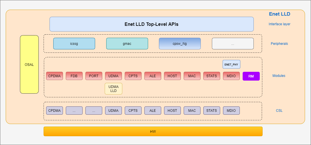
Enet LLD is an unified Ethernet driver that support Ethernet peripherals found in TI SoCs, such as CPSW and ICSSG. Enet LLD supports CPSW_2G, ICSSG Dual-MAC and ICSSG Switch in AM65xx devices.
The diagram below shows the overall software architecture of the Enet low-level driver. A top-level driver layer provides the interface that the applications can use to configure the switch and to send/receive Ethernet frames.
For instance, the CPSW support in the Enet driver consists of several software submodules that mirror those of the CPSW hardware, like DMA, ALE, MAC port, host port, MDIO, etc. Additionally, the Enet driver also includes PHY driver support as well as a resource manager to administrate the CPSW resources.
Enet LLD relies on other PDK drivers like UDMA for data transfer to/from the Ethernet peripheral’s host port to the other processing cores inside the TI SoC devices. For the lower level access to the hardware registers, Enet LLD relies on the Chip Support Library (CSL).
4.6. ICSSG
ICSSG Dual-MAC and Switch are both supported in Enet LLD on AM65xx devices. Currently, MCU R5F core is the only core where support has been added. Integration with lwIP stack package has been enabled for ICSSG Dual-MAC, but not for ICSSG Switch.
Note
PRU Port Transmit queues should be place in the MSMC memory in order to get maximum throughput from PRUs. Placing in any other memory location will significantly impact the throughput and also TX underflow events can occur.
The following tables summarize the features support by ICSSG Dual-MAC and Switch.
4.6. ICSSG Dual-MAC
| Feature | Remarks |
|---|---|
| VLAN classification and ingress filtering | Supported |
| FDB Multicast filtering | Supported |
| Ethernet QoS | Support up to 8 queues |
| 802.1as support | Support Working Clock |
| 802.1Qbv support | Supported |
| 802.1Qbu support | Supported |
| Port state configuration | Supported |
| Acceptable frame type configuration | Supported values are
|
| Statistics | Supported |
4.6. ICSSG Switch
| Feature | Remarks |
|---|---|
| 2-Port cutthrough switch | Supported |
| VLAN classification and ingress filtering | Supported |
| FDB Multicast filtering | Supported |
| Ethernet QoS | Support up to 8 queues |
| Priority regeneration | Supported |
| 802.1as support | Support Working Clock |
| 802.1Q learning bridge for MAC addresses | Supported - Shared VLAN configuration only |
| 802.1Qbv support | Supported |
| 802.1Qbu support | Supported |
| Buffering | Validated up to 200us - Buffer configurable from application |
| Port State configuration | Independently configurable on each port |
| Acceptable frame type configuration | Supported values are:
|
| Statistics | Supported |
4.6.2. User Interface
For details about individual fields of this library structure, see the PDK doxygen documentation
4.6.2.1. APIs
The Enet LLD APIs can be broadly divided into two categories: control and data path. The control APIs can be used to configure all Ethernet hardware submodules like FDB, MAC port, host port, MDIO, statistics, as well as PHY drivers and resource management. The data path APIs are exclusive for the DMA-based data transfers between the TI SoC processing cores and the Ethernet peripheral.
API reference for application:
#include <ti/drv/enet/enet.h>
The main APIs of the Enet LLD are the following:
- Enet_open()
- Enet_close()
- Enet_ioctl()
- Enet_poll()
- Enet_periodicTick()
4.6.2.1.1. Data Path APIs
The main Enet LLD functions used to send and receive packets are:
- EnetDma_openRxCh()
- EnetDma_closeRxCh()
- EnetDma_openTxCh()
- EnetDma_closeTxCh()
- EnetDma_retrieveRxPktQ()
- EnetDma_submitRxPktQ()
- EnetDma_retrieveTxPktQ()
- EnetDma_submitTxPktQ()
It’s worth noting that the control path APIs are mainly IOCTL-based, and the data path APIs are direct functions in order to avoid any additional overhead associated with IOCTL calls as DMA data operations occur highly frequently.
4.6.2.1.2. IOCTL Interface
IOCTLs are system calls that take an argument specifying the command code and
can take none or additional parameters via Enet_IoctlPrms argument.
IOCTL are used by all Enet submodules except for DMA.
The Enet_IoctlPrms parameter structure consists of input and output
argument pointers and their corresponding size. The following helper macros are
provided to help construct the IOCTL params:
ENET_IOCTL_SET_NO_ARGS(prms). Used for IOCTL commands that take no parameters.ENET_IOCTL_SET_IN_ARGS(prms, in). Used for IOCTL commands that take input parameters but don’t output any parameter.ENET_IOCTL_SET_OUT_ARGS(prms, out). Used for IOCTL commands that don’t take input parameters but return output parameters.ENET_IOCTL_SET_INOUT_ARGS(prms, in, out). Used for IOCTL commands that take input parameters and also return output parameters.
where prms in a pointer to Enet_IoctlPrms variable, in is the pointer
to IOCTL input argument and out is the pointer to IOCTL output argument.
It’s recommended that the application doesn’t set the Enet_IoctlPrms
members individually, but only through the helper macros listed above.
Please refer to the individual IOCTL command to find out if it requires input and/or output parameters.
4.6.3. lwIP Integration
See lwIP User’s Guide for further information about lwIP integration into PDK using Enet LLD, and NDK-to-lwIP migration guide.
4.6.4. Application
4.6.4.1. Examples
Enet LLD comes with a set of examples demonstrating the usage of driver APIs. The examples are:
- enet_loopback: Internal (MAC port) or external loopback test.
- enet_lwip_example: TCP/IP stack integration using lwIP.
- enet_multiport: ICSSG and CPSW multiport test app.
- enet_tas: ICSSG Time Aware Shaper test app.
| Name | Description | Expected Results | Cores Supported | Peripherals |
|---|---|---|---|---|
| Loopback | Enet Loopback example demonstrates basic packet send and receive on an Ethernet peripheral configured in MAC loopback or PHY loopback. | All packets sent from the example application shall be received back after being looped in MAC or PHY. | mcu1_0 |
|
| lwIP | Enet lwIP example demonstrates Enet driver integration with open source lwIP TCP/IP stack. The example runs DHCP client, it can get an IP address when connected to a network. | lwIP example application shall be able to get an IP address when connected to a network. User can test ‘ping’, ‘echo’ and ‘iperf’. | mcu1_0 |
|
| Multiport | Enet Multiport example demonstrates Enet driver capability to support multiple peripherals simultaneously. CPSW and all ICSSG peripherals can be opened simultaneously. This example application implements an RX to TX loopback data path. Tx and RX packet timestamping is also demonstrated this example. A companion Linux host application is provided to facilitate packet send/receive to the device. |
Multiport example app shall respond to all packets sent into a MAC port either via provided Linux host app or other traffic generator. RX-to-TX timestamp difference shall be printed on UART terminal when packet timestamping is enabled via application’s menu. |
mcu1_0 |
|
| TAS | Enet TAS example demonstrates Enet driver capability to support Time Aware shaper support with multiple ICSSG peripherals simultaneously. | This example application verifies if All the packets transmitted have their tx timestamp within their corresponding windows. | mcu1_0 |
|
4.6.4.1.1. Enet loopback
This example exercises the MAC loopback functionality of the hardware. The example is developed and tested on both bare metal and TI RTOS code base. The Ethernet peripheral is opened with default initialization parameters and the MAC loopback is enabled.
A Tx channel and a Rx flow are opened to enable data transfers. Packets are transmitted from the Switch R5F (Main R5F0_0) to the host port using the Tx channel. These packets are routed back to the host port by the switch hardware as the internal loopback feature is enabled. These packets are then transmitted to the Switch R5F by the Rx flow and the application is notified.
The Tx and Rx functions in the example are set to transmit and receive 10000 packets. After reaching the count of 10000, the application closes the Tx channel, Rx flow, peripheral (i.e. CPSW) and restarts the application for a configurable number of times. Restarting the loopback test application ensures that there aren’t any memory leaks, and the hardware is closed properly and can be reopened any time.
4.6.4.1.2. Enet LWIP
Building LWIP example
Enabling specific features in the test
To configure what gets built in the example, navigate to the example directory
pdk/packages/ti/drv/enet/examples/enet_lwip_exampleand find thelwipcfg.hfile. Inside, change the macros corresponding to the program that you wish to build to 1.For example, if udpecho is required, set:
#define LWIP_UDPECHO_APP 1Note
The heap memory may need to be increased in the
FreeRTOSConfig.hfile to accomodate multiple apps.
To build the lwip example, issue the following command:
make -s enet_lwip_example_freertos
Running LWIP example
Load and run the enet_lwip_example image from the corresponding binaries folder.
The setup requires a LAN cable to be connected between the device and a multiport-router for the link status to be UP and aquire an IP address.
Connect the LAN cable between the same router and Laptop/PC from where the ping/echo tests are run.
Wait until the local interface IP is assigned and printed on the console like below.
Starting lwIP, local interface IP is dhcp-enabled
CPSW_2G Test on MCU NAVSS
EnetPhy_bindDriver: PHY 0: OUI:080028 Model:23 Ver:01 <-> 'dp83867' : OK
PHY 0 is alive
Host MAC address: 70:ff:76:01:02:03
[LWIPIF_LWIP] CPSW has been started successfully
[LWIPIF_LWIP] NETIF INIT SUCCESS
status_callback==UP, local interface IP is 0.0.0.0
Cpsw_handleLinkUp: Port 1: Link up: 100-Mbps Full-Duplex
MAC Port 1: link up
link_callback==UP
status_callback==UP, local interface IP is 192.168.0.9
Initializing apps
UDP server listening on port 5001
Testing LWIP example
Prerequisites: LAN cable setup and device link is UP and Local interface IP is successfully aquired.
Ping test
ping -t <ip_addr>
ping -t 192.168.0.9
UDP/ TCP echo test
Download echotool from this website and execute the commands to see the response.
UDP echo command:
echotool.exe <ip_addr> /p udp /r 7 /n 0
echotool.exe 192.168.0.9 /p udp /r 7 /n 0
TCP echo command:
echotool.exe <ip_addr> /p tcp /r 7 /n 0
echotool.exe 192.168.0.9 /p tcp /r 7 /n 0
iperf test
Download iperf2 from iperf website and execute the commands to see the response.
iperf TCP test command:
iperf.exe -c <ip_addr> -r
iperf.exe -c 192.168.0.9 -r
iperf UDP test command:
iperf.exe -c <ip_addr> -r -u
iperf.exe -c 192.168.0.9 -r -u
Static IP
The Enet lwIP example uses DHCP by default. If static IP needs to be tested, the following
two config options need to be disabled in examples/enet_lwip_example/lwipcfg.h.
#define USE_DHCP    0
#define USE_AUTOIP  0
The IP address, gateway and netmask can be set in the same lwipcfg.h file.
#define LWIP_PORT_INIT_IPADDR(addr)   IP4_ADDR((addr), 192,168,1,200)
#define LWIP_PORT_INIT_GW(addr)       IP4_ADDR((addr), 192,168,1,1)
#define LWIP_PORT_INIT_NETMASK(addr)  IP4_ADDR((addr), 255,255,255,0)
4.6.4.1.3. Enet Multiport
The multiport example is dedicated to demonstrate simultaneous usage of Enet ICSSG peripherals operating in either Dual-MAC mode or Switch mode. A total of up to 6 ICSSG MAC ports can be tested simultaneously with this example application.
This example application also supports CPSW2G peripheral present in AM65xx devices.
This example has two components:
Target-side application running on a Cortex R5F core.
- One TX channel and one RX flow are opened for each available MAC port.
- Application receives the packet, copies the payload into a new packet which is then sent back.
- The application has a menu to enable/disable features, such as packet timestamping. This menu along with application logs are implemented via UART.
Host-side application.
- This is a Linux command-line application meant to simplify testing of the multiport example, it uses a raw socket to send and receive packets.
- Alternatively, other application could be used as well: packETH tool can be used to generate and send packets, Wireshark can be used to receive and verify packet contents.
The diagram below shows the enabled data paths for the Ethernet peripherals in AM65xx device. Note that the example application opens all these peripherals simultaneously, but it’s not mandatory to have all ports connected at the same time. Tests can be run with the connected ports.
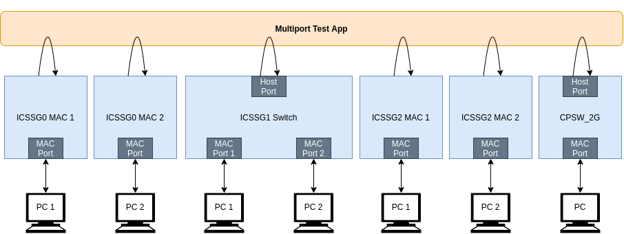
The data path enabled in this example is as follows:
Note
User can change the ICSSG mode to ENETMP_DUALMAC mode or ENETMP_SWITCH mode by changing below macros in enet_multiport.c file during compile time.
- #define ENETMP_ICSSG0_MODE (ENETMP_DUALMAC)
- #define ENETMP_ICSSG1_MODE (ENETMP_SWITCH)
- #define ENETMP_ICSSG2_MODE (ENETMP_DUALMAC)
Host side (PC) application sends a packet to an AM65xx IDK MAC port.
- Based on Switch mode or Dual-MAC mode the data flow will differ.
- In Switch mode:
- If packet is non directed unicast(UC) packet, it will be only forwarded.
- If packet is directed unicast(UC) packet, it will be sent only to target application.
- If packet is multicast(MC) or broadcast(BC) packet, it will be forwarded as well as sent to target application.
- In Dual-MAC mode:
- If packet is Non directed unicast(UC) packet it will be dropped.
- If packet is directed unicast(UC) or multicast(MC) or broadcast(BC) packet, it will be sent to target application.
- By default, a broadcast packet is sent but the user can specify any other MAC address.
Target side application receives the packet, updates the MAC addresses in the Layer-2 header and sends the packet back.
Host side application receives the packet and checks if the payload matched what it had sent in step 1.
Packet timestamping can be enabled/disabled at any time via target-side application menu. Enabling timestamping implies that both RX and TX timestamps will be enabled.
Note
Currently, this example is supported only in TI AM65xx Industrial Development Kit (IDK) which provides:
- 6 x ICSSG MAC ports or 3 x ICSSG Switch peripherals
- 1 x CPSW2G MAC port.
Running Multiport example
Launch a CCS debug session, load and run the example image from the corresponding binaries folder.
You will see logs in the UART terminal as shown in the next section.
Wait until the interface MAC ID is assigned and printed on the console like below.
Init Enet's OSAL and utils to use defaults
Init memory utils
Create clock and task for periodic tick
Create periodic tick task
Create periodic tick clock
Open Main UDMA driver
Open MCU UDMA driver

Init all peripheral clocks
----------------------------------------------
Enabling clocks!
Enabling clocks!
Enabling clocks!
Enabling clocks!
Enabling clocks!
Enabling clocks!

Init all configs
----------------------------------------------
cpsw-2g: init config
icssg0-p1: init config
icssg0-p2: init config
icssg1: init config
icssg2-p1: init config
icssg2-p2: init config

Open all peripherals
----------------------------------------------
cpsw-2g: Open enet
icssg0-p1: Open enet
icssg0-p1: Register async IOCTL callback
icssg0-p1: Register TX timestamp callback
icssg0-p2: Open enet
Icssg_open: icssg0-2: TimeSync cannot be enabled, IEP0 already in use
icssg0-p2: Register async IOCTL callback
icssg0-p2: Register TX timestamp callback
icssg1: Open enet
icssg1: Register async IOCTL callback
icssg1: Register TX timestamp callback
icssg2-p1: Open enet
icssg2-p1: Register async IOCTL callback
icssg2-p1: Register TX timestamp callback
icssg2-p2: Open enet
Icssg_open: icssg2-2: TimeSync cannot be enabled, IEP0 already in use
icssg2-p2: Register async IOCTL callback
icssg2-p2: Register TX timestamp callback

Attach core id 1 on all peripherals
----------------------------------------------
cpsw-2g: Attach core
icssg0-p1: Attach core
icssg0-p2: Attach core
icssg1: Attach core
icssg2-p1: Attach core
icssg2-p2: Attach core

Create RX tasks
----------------------------------------------
cpsw-2g: Create RX task
icssg0-p1: Create RX task
icssg0-p2: Create RX task
icssg1: Create RX task
icssg2-p1: Create RX task
icssg2-p2: Create RX task
cpsw-2g: Open port 1
cpsw-2g: Open port 1 link
EnetPhy_bindDriver: PHY 0: OUI:080028 Model:23 Ver:01 <-> 'dp83867' : OK
cpsw-2g: Waiting for link up...
icssg0-p2: Open port 1
icssg0-p2: Open port 1 link

Enet Multiport Menu:
'p'  -  Toggle promiscuous mode
'T'  -  Enable timestamp prints
't'  -  Disable timestamp prints
's'  -  Print statistics
'r'  -  Reset statistics
'm'  -  Show allocated MAC addresses
'x'  -  Stop the test

icssg2-p1: Open port 1
icssg2-p1: Open port 1 link
EnetPhy_bindDriver: PHY 3: OUI:080028 Model:23 Ver:01 <-> 'dp83867' : OK
icssg0-p2: Waiting for link up...
icssg1: Open port 1
icssg1: Open port 1 link
icssg2-p2: Open port 1
icssg2-p2: Open port 1 link
icssg0-p1: Open port 1
icssg0-p1: Open port 1 link
EnetPhy_bindDriver: PHY 0: OUI:080028 Model:23 Ver:01 <-> 'dp83867' : OK
icssg2-p1: Waiting for link up...
EnetPhy_bindDriver: PHY 0: OUI:080028 Model:23 Ver:01 <-> 'dp83867' : OK
icssg1: Open port 2
icssg1: Open port 2 link
EnetPhy_bindDriver: PHY 3: OUI:080028 Model:23 Ver:01 <-> 'dp83867' : OK
icssg2-p2: Waiting for link up...
EnetPhy_bindDriver: PHY 0: OUI:080028 Model:23 Ver:01 <-> 'dp83867' : OK
EnetPhy_bindDriver: PHY 3: OUI:080028 Model:23 Ver:01 <-> 'dp83867' : OK
icssg0-p1: Waiting for link up...
icssg1: Waiting for link up...
Icssg_handleLinkUp: icssg0-1: Port 1: Link up: 1-Gbps Full-Duplex
Icssg_handleLinkUp: icssg0-2: Port 1: Link up: 1-Gbps Full-Duplex
icssg0-p1: Port 1 link is up
icssg0-p1: Set port state to 'Forward'
icssg0-p1: Async IOCTL completed
icssg0-p1: Open DMA
icssg0-p2: Port 1 link is up
icssg0-p2: Set port state to 'Forward'
icssg0-p2: Async IOCTL completed
icssg0-p2: Open DMA
initQs() txFreePktInfoQ initialized with 128 pkts
initQs() txFreePktInfoQ initialized with 256 pkts
icssg0-p2: Set MAC addr: 70:ff:76:1d:92:c5
icssg0-p1: Set MAC addr: 70:ff:76:1d:92:c3
Then we can start sending packets from packETH tool or Colasoft Pkt Builder and capture the packets in Wireshark.
User can check the Statistics by providing input ‘s’ in UART console and the results looks like below
Enet Multiport Menu:
'p'  -  Toggle promiscuous mode
'T'  -  Enable timestamp prints
't'  -  Disable timestamp prints
's'  -  Print statistics
'r'  -  Reset statistics
'm'  -  Show allocated MAC addresses
'x'  -  Stop the test

s
Print statistics
----------------------------------------------

cpsw-2g - Port 1 statistics
--------------------------------

icssg0-p1 - PA statistics
--------------------------------
  hostRxByteCnt              = 25600
  hostTxByteCnt              = 24800
  hostRxPktCnt               = 200
  hostTxPktCnt               = 200

icssg0-p1 - Port 1 statistics
--------------------------------
  rxGoodFrames            = 100
  rxBCastFrames           = 100
  rxMCastFrames           = 100
  rxClass8                = 100
  rxClass9                = 100
  rxBucket2SizedFrame     = 100
  rxTotalByte             = 12800
  rxTxTotalByte           = 26400
  txGoodFrame             = 100
  txBucket3SizedFrame     = 100
  txTotalByte             = 13600

icssg0-p2 - PA statistics
--------------------------------
  hostRxByteCnt              = 25600
  hostTxByteCnt              = 24800
  hostRxPktCnt               = 200
  hostTxPktCnt               = 200

icssg0-p2 - Port 1 statistics
--------------------------------
  rxGoodFrames            = 100
  rxBCastFrames           = 100
  rxMCastFrames           = 100
  rxClass8                = 100
  rxClass9                = 100
  rxBucket2SizedFrame     = 100
  rxTotalByte             = 12800
  rxTxTotalByte           = 26400
  txGoodFrame             = 100
  txBucket3SizedFrame     = 100
  txTotalByte             = 13600

icssg1 - PA statistics
--------------------------------
icssg1 - Port 1 statistics
--------------------------------
icssg1 - Port 2 statistics
--------------------------------
icssg2-p1 - PA statistics
--------------------------------
icssg2-p1 - Port 1 statistics
--------------------------------
icssg2-p2 - PA statistics
--------------------------------
icssg2-p2 - Port 1 statistics
--------------------------------
4.6.4.1.4. Enet TAS
The TAS example is dedicated to demonstrate Time-Aware Shaper functionality on ICSSG Switch and Dual-MAC peripherals.
This example has two components:
Target-side application running on a Cortex R5F core.
- One TX channel and one RX flow are opened for each available MAC port.
- The application has a menu to start the TAS test and to Print or Reset the Statistics. This menu along with application logs are implemented via UART.
Host-side application.
- Wireshark can be used to receive and verify packet contents.
Below shows the configuration used for the Time Aware Shaper whichis used to configure each MAC port in AM65xx device. Note that the example application opens all these peripherals simultaneously, but it’s not mandatory to have all ports connected at the same time. Tests can be run with the connected ports.:
              |<------------- Cycle time = 250 us --------------->|

              +------------+------------+------------+------------+
              |            |            |            |            |
              +------------+------------+------------+------------+

              |<---------->|<---------->|<---------->|<---------->|
Window index       0             1            2            3
Duration         62.5 us       62.5 us      62.5 us      62.5 us
Gate mask      0b00000011    0b00001100   0b00110000   0b11000000
- The default cycle time is set to be 250us and each window is equally divided in the cycle as shown above.
- The startTasTest test case configures each of the MAC ports with the above-mentioned configuration and transmits 2 packets each with traffic class values varying from 0 to 7.
- As per the TAS configuration the packets with traffic class of 0 and 1 will only be transmitted within the time duration of window index 0, traffic class 2 and 3 will be transmitted in window index 1 and so on.
- The startTasTest test case verifies if all the packets transmitted have their tx timestamp within their corresponding windows. If this condition is satisfied then test is marked as passed.
- The test is repeated for all ports with link up.
Note
Currently, this example is supported only in TI AM65xx Industrial Development Kit (IDK) which provides:
- 6 x ICSSG MAC ports or 3 x ICSSG Switch peripherals
Running TAS example
Launch a CCS debug session, load and run the example image from the corresponding binaries folder.
You will see logs in the UART terminal as shown in the next section.
Wait until the interface MAC ID is assigned and printed on the console like below.
Init Enet's OSAL and utils to use defaults
Init memory utils
Create clock and task for periodic tick
Create periodic tick task
Create periodic tick clock
Open Main UDMA driver

Init all peripheral clocks
----------------------------------------------
Enabling clocks!
Enabling clocks!
Enabling clocks!
Enabling clocks!
Enabling clocks!

Init all configs
----------------------------------------------
icssg0-p1: init config
icssg0-p2: init config
icssg1-p1: init config
icssg1-p2: init config
icssg2: init config

Open all peripherals
----------------------------------------------
icssg0-p1: Open enet
icssg0-p1: Register async IOCTL callback
icssg0-p1: Register TX timestamp callback
icssg0-p2: Open enet
Icssg_open: icssg0-2: TimeSync cannot be enabled, IEP0 already in use
icssg0-p2: Register async IOCTL callback
icssg0-p2: Register TX timestamp callback
icssg1-p1: Open enet
icssg1-p1: Register async IOCTL callback
icssg1-p1: Register TX timestamp callback
icssg1-p2: Open enet
Icssg_open: icssg1-2: TimeSync cannot be enabled, IEP0 already in use
icssg1-p2: Register async IOCTL callback
icssg1-p2: Register TX timestamp callback
icssg2: Open enet
icssg2: Register async IOCTL callback
icssg2: Register TX timestamp callback

Attach core id 1 on all peripherals
----------------------------------------------
icssg0-p1: Attach core
icssg0-p2: Attach core
icssg1-p1: Attach core
icssg1-p2: Attach core
icssg2: Attach core

Create RX tasks
----------------------------------------------
icssg0-p1: Create RX task
icssg0-p2: Create RX task
icssg1-p1: Create RX task
icssg1-p2: Create RX task
icssg2: Create RX task
icssg0-p1: Open port 1
icssg0-p1: Open port 1 link
EnetPhy_bindDriver: PHY 0: OUI:080028 Model:23 Ver:01 <-> 'dp83867' : OK
icssg0-p1: Waiting for link up...
icssg2: Open port 1
icssg2: Open port 1 link
EnetPhy_bindDriver: PHY 0: OUI:080028 Model:23 Ver:01 <-> 'dp83867' : OK
icssg2: Open port 2
icssg2: Open port 2 link
EnetPhy_bindDriver: PHY 3: OUI:080028 Model:23 Ver:01 <-> 'dp83867' : OK
icssg2: Waiting for link up...
icssg1-p2: Open port 1
icssg1-p2: Open port 1 link
EnetPhy_bindDriver: PHY 3: OUI:080028 Model:23 Ver:01 <-> 'dp83867' : OK
icssg1-p2: Waiting for link up...
icssg0-p2: Open port 1
icssg0-p2: Open port 1 link
EnetPhy_bindDriver: PHY 3: OUI:080028 Model:23 Ver:01 <-> 'dp83867' : OK
icssg0-p2: Waiting for link up...
icssg1-p1: Open port 1
icssg1-p1: Open port 1 link
EnetPhy_bindDriver: PHY 0: OUI:080028 Model:23 Ver:01 <-> 'dp83867' : OK
icssg1-p1: Waiting for link up...

Enet Tas Test Menu:
'T'  -  Start the TAS test with default config
's'  -  Print statistics
'r'  -  Reset statistics
'x'  -  Stop the test

Icssg_handleLinkUp: icssg0-1: Port 1: Link up: 1-Gbps Full-Duplex
Icssg_handleLinkUp: icssg0-2: Port 1: Link up: 1-Gbps Full-Duplex
icssg0-p1: Port 1 link is up
icssg0-p1: Set port state to 'Forward'
icssg0-p1: Async IOCTL completed
icssg0-p2: Port 1 link is up
icssg0-p2: Set port state to 'Forward'
icssg0-p2: Async IOCTL completed
icssg0-p1: Open DMA
icssg0-p2: Open DMA
initQs() txFreePktInfoQ initialized with 128 pkts
icssg0-p1: Set MAC addr: 70:ff:76:1d:92:c1
initQs() txFreePktInfoQ initialized with 256 pkts
icssg0-p2: Set MAC addr: 70:ff:76:1d:92:c3
User can start the TAS test with default config by providing input ‘T’ in UART console and the results looks like below
Enet Tas Test Menu:
'T'  -  Start the TAS test with default config
's'  -  Print statistics
'r'  -  Reset statistics
'x'  -  Stop the test

T
Success: IOCTL command sent for making MAC entry in FDB
icssg0-p1: Async IOCTL completed
Success: IOCTL command sent for making MAC entry in FDB
icssg0-p1: Async IOCTL completed
icssg0-p1: Async IOCTL completed
icssg0-p1: Async IOCTL completed
icssg0-p1: Async IOCTL completed
Transmitting 10 packets
Packet 0 is within window timestamp : 33648 window_start : 0 window_end : 62500
Packet 1 is within window timestamp : 1312 window_start : 0 window_end : 62500
Packet 2 is within window timestamp : 97224 window_start : 62500 window_end : 125000
Packet 3 is within window timestamp : 108788 window_start : 62500 window_end : 125000
Packet 4 is within window timestamp : 130784 window_start : 125000 window_end : 187500
Packet 5 is within window timestamp : 142336 window_start : 125000 window_end : 187500
Packet 6 is within window timestamp : 189376 window_start : 187500 window_end : 250000
Packet 7 is within window timestamp : 188184 window_start : 187500 window_end : 250000
Packet 8 is within window timestamp : 3720 window_start : 0 window_end : 62500
Packet 9 is within window timestamp : 2504 window_start : 0 window_end : 62500
Packet 10 is within window timestamp : 64408 window_start : 62500 window_end : 125000
Packet 11 is within window timestamp : 63212 window_start : 62500 window_end : 125000
Packet 12 is within window timestamp : 126896 window_start : 125000 window_end : 187500
Packet 13 is within window timestamp : 125704 window_start : 125000 window_end : 187500
Packet 14 is within window timestamp : 189696 window_start : 187500 window_end : 250000
Packet 15 is within window timestamp : 188504 window_start : 187500 window_end : 250000
ENET Tas Test PASSED
Success: IOCTL command sent for making MAC entry in FDB
icssg0-p2: Async IOCTL completed
Success: IOCTL command sent for making MAC entry in FDB
icssg0-p2: Async IOCTL completed
icssg0-p2: Async IOCTL completed
icssg0-p2: Async IOCTL completed
icssg0-p2: Async IOCTL completed
Transmitting 10 packets
Packet 0 is within window timestamp : 2480 window_start : 0 window_end : 62500
Packet 1 is within window timestamp : 1288 window_start : 0 window_end : 62500
Packet 2 is within window timestamp : 64656 window_start : 62500 window_end : 125000
Packet 3 is within window timestamp : 63460 window_start : 62500 window_end : 125000
Packet 4 is within window timestamp : 126856 window_start : 125000 window_end : 187500
Packet 5 is within window timestamp : 125660 window_start : 125000 window_end : 187500
Packet 6 is within window timestamp : 189416 window_start : 187500 window_end : 250000
Packet 7 is within window timestamp : 188220 window_start : 187500 window_end : 250000
Packet 8 is within window timestamp : 2736 window_start : 0 window_end : 62500
Packet 9 is within window timestamp : 1540 window_start : 0 window_end : 62500
Packet 10 is within window timestamp : 112712 window_start : 62500 window_end : 125000
Packet 11 is within window timestamp : 63448 window_start : 62500 window_end : 125000
Packet 12 is within window timestamp : 140452 window_start : 125000 window_end : 187500
Packet 13 is within window timestamp : 162748 window_start : 125000 window_end : 187500
Packet 14 is within window timestamp : 190632 window_start : 187500 window_end : 250000
Packet 15 is within window timestamp : 196964 window_start : 187500 window_end : 250000
ENET Tas Test PASSED
icssg1-p1: Skipping Test due to link not UP
icssg1-p2: Skipping Test due to link not UP
icssg2: Skipping Test due to link not UP