5. EVM Setup for AM65xx
This section is intended to give a quick reference of IDK/EVM related to SDK usage. Full IDK/EVM documentation can be referenced at AM65x evaluation module https://www.ti.com/tool/TMDX654IDKEVM and https://www.ti.com/tool/TMDX654GPEVM.
Important
The power supply current requires more than 1A @12V input
DisplayPort-to-DVI or DisplayPort-to-HDMI adapters don’t work with DisplayPort
The SOM board has to be tightly inserted into the connector sockets.
5.1. EVM Setup to run SDK demos
5.1.1. Daughter card requirements
Below table shows the daughter cards required for various features/demos
Feature |
IDK Application card |
PCIe Adapter card |
|---|---|---|
Industrial Protocols |
REQUIRED |
na |
PCIe applications |
na |
REQUIRED |
CAN applications |
REQUIRED |
na |
5.1.2. UART terminal setup
Connect USB cable to FTDI USB port (J42) on common processor board (see IDK Application Board)
4 UART ports would be visible at the PC side
First COM port – SoC MAIN UART0
Second COM port – MCU UART
Third COM port – Wakeup UART
Fourth COM port – SoC MAIN UART1
Setup UART for 115200 baud rate, 8 data bits, no party, 1 stop bit
5.1.3. Boot Modes
Bootmodes are selected using the SW2 and SW3 switches on the common processor board. See the image below
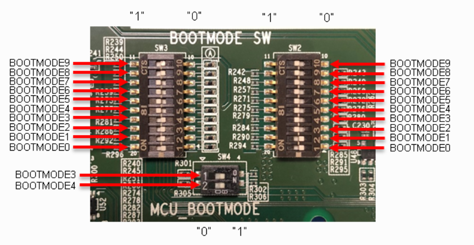
Note that 0 indicates OFF and 1 indicates ON
No Boot Mode
Use following settings for MCU_BOOTMODE pins
SW4[1-2] = 00
5.1.3.1. No Boot Mode
When you want the binaries to be loaded from a debugger (CCS), the common processor boards has to be set in the NO boot mode.
Following are the switch settings to do the same.:
SW2[1-8] = 0010 0000
SW3[1-8] = 0000 0000
5.1.3.2. SD Boot Mode
Following are the switch settings to set the boot mode to SD for common processor board.:
SW2[1-8] = 0010 0000
SW3[1-8] = 0110 0000
5.1.3.3. OSPI Boot Mode
Following are the switch settings to set the boot mode to OSPI for common processor board.:
SW2[1-8] = 1000 0000
SW3[1-8] = 1000 0000
5.1.3.4. UART Boot Mode
Following are the switch settings to set the boot mode to SD for common processor board.:
SW2[1-8] = 0010 0000
SW3[1-8] = 0101 0000
5.2. EVM and Daughter Card information
The EVM/IDK with all the daughter cards connected looks like this:
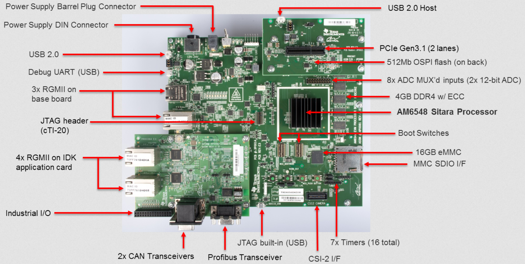
Fig. 5.1 AM65XX EVM/IDK
5.2.1. AM65XX Common Processor Board
The AM65XX Evaluation Module consists of a Common Processor Board, IDK application board and a two lane PCIe adapter card.
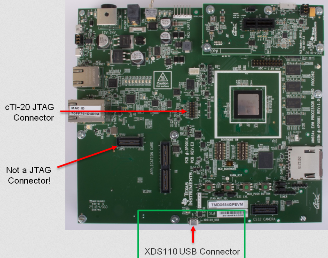
Fig. 5.2 AM65XX Common Processor Board
Contents of the board
4xUART to USB port for UART ports
Ethernet
CPSW 2G port (MCU Ethernet)
1x ICSSG port
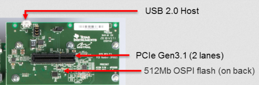
4 GB DDR w/ ECC
512Mb OSPI flash
USB 2.0
16GB eMMC
MMC SDIO I/F
SD card slot
XDS110 on board USB JTAG connector
MIPI JTAG connector
12V Power input
Power switch
Boot Switches
5.2.2. IDK Application Board
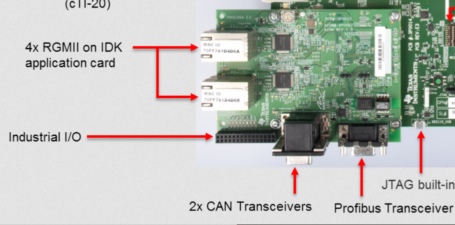
Fig. 5.3 IDK Application card
IDK Applicatin card is an adapter card used to showcase Industrial Protocols like EthernetIP, Profinet, Profibus etc. It’s also possible to show CAN capabilities with the 2x CAN ports on the board.
Contents of the board:
4x ICSSG Ethernet
Industrial IO pins
2x CAN transceivers
Profibus Transceiver