7.1. Template Application Workshop
7.1.1. Introduction
Note
This workshop duplicates information found elsewhere in the RTOS Software Developer Guide for the purpose of creating a cohesive document.
This workshop is a simple introduction for software development using Processor SDK RTOS. The goal of this workshop is to get you familiarized with Processor SDK RTOS and introduce you to using Sitara Evaluation Modules (EVMs) and TI tools.
To accomplish this goal, we will work through an interactive lab using the RTOS/Bare-metal Template Application. This application will introduce key concepts of the SDK and serves as the starting point for creating your own application.
Here’s what we will learn over the course of this lab:
Basic usage of Code Composer Studio (CCS)
Importing
Editing
Building
Flashing
Processor SDK RTOS Software
Low level drivers (LLDs) such as UART, GPIO, etc.
Operating System Abstraction Layer (OSAL)
Board library
7.1.2. Prerequisites
7.1.2.1. Software
Processor SDK RTOS for your platform
CCS Version associated with your SDK Release
A download link for CCS is located on the same page as the SDK download.
Note
If you are using AM65x, you will also need to install latest TI Emulators and Sitara device support packages into CCS. This can be done through CCS –> Help –> Check for Updates.
7.1.2.2. Hardware
A supported Sitara Evaluation Module
Serial UART cable provided in the EVM kit
7.1.2.3. Recommended Training Videos
-
Introduction to the Processor SDK Training Series
Processor SDK Overview
Introduction to Processor SDK RTOS Part 1
Introduction to Processor SDK RTOS Part 2
Application Development Using Processor SDK RTOS
7.1.3. Template Application Overview
The Template Application is intended for customers to use as a starting point during software development using Processor SDK RTOS software. The Template Application can be quickly brought up by importing the included Code Composer Studio (CCS) project into the CCS development environment. The application currently includes the typical low level drivers such as UART, GPIO, and I2C, the OSAL layer, and Board Library. For additional details refer to the README.txt file in the installed package.
7.1.3.1. Components Used
SYS/BIOS (RTOS only)
XDCTools (RTOS only)
Processor SDK RTOS PDK
Drivers, OSAL, etc.
7.1.3.2. Software Design
The Template Application is designed to provide a foundational project with a clean separation of the application-specific submodule from the startup and initialization code. This gives users the ability to focus on application-specific code and quickly get it up and running. This separation is achieved by splitting the “main” and “app” submodules into different files.
The source files are organized as follows:
└── template_app
    ├── baremetal
    │   ├── app.c --> Application tasks are here
    │   ├── app.h --> Application header file
    │   ├── baremetal_template_app_am65xx_a53_evmAM65xx.projectspec --> Project spec file
    |   └── main.c --> Main file which has board and driver init code
    ├── GPIO_board.h --> Gpio board header
    ├── GPIO_evmAM65xx_board.c --> Gpio board configuration
    ├── linker_a53.lds --> Linker command file.
    └── rtos
        ├── app.c --> Application tasks are here
        ├── app.h --> Application header file
        ├── main.c --> Main file which has board and driver init code
        ├── main.cfg --> Main BIOS config file
        └── rtos_template_app_am65xx_a53_evmAM65xx.projectspec --> Project spec file
In general, to write a new application app.c and app.h can be modified, recompiled, and run.
7.1.4. Lab
Now that the introductory material is out of the way, it is time to get our hands dirty and begin the lab.
7.1.4.1. Task 1 - Installing the Processor SDK into CCS
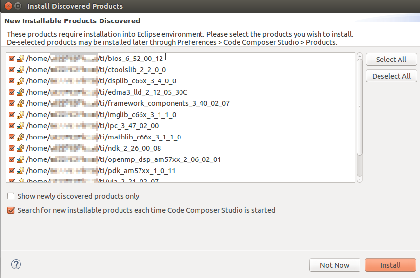
Before using the Processor SDK, we must install its components into Code Composer Studio (CCS). Typically – if you chose to install the Software Development Kit (SDK) into the default $HOME/ti or C:\ti location – CCS will automatically detect the new products the next time it is opened and prompt you to install them. If you are not prompted to install the new products, you can do so manually through the Window –> Preferences –> Code Composer Studio –> Products menu. This menu will allow you define product discovery paths and rediscover, install, and unistall products.
For more info on setting up CCS. Check out CCS Setup for AM65XX.
7.1.4.2. Task 2 - Importing and Building the Template Application
We begin the lab by importing the RTOS or Bare-metal Template Application into CCS. The Template Application is delivered as a preconfigured CCS Project, making this process very simple. We will also use this as an opportunity to briefly dive into the structure of the SDK.
To import a project into CCS, go to the Project –> Import CCS Projects… menu. Typically, you will import SDK projects from either the pdk_<platform>_<version> or processor_sdk_rtos_<platform>_<version> directories. The pdk_<platform>_<version> directory contains Chip Support Library (CSL), Low Level Drivers (LLDs), Boot, Diagnostics, and other functions. It is also where LLD example projects are created. The processor_sdk_rtos_<platform>_<version> directory contains demos (including the Template App), documentation, and resources for creating bootable SD cards.
Now that you have an understanding of these directories, let us move on to importing the Template Application.
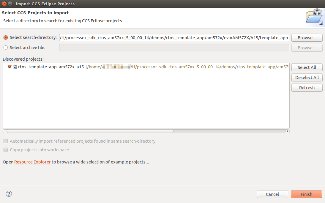
To import a project into CCS open the Project –> Import CCS Projects… menu. Then click Browse… to locate the template app which can be found at: processor_sdk_rtos_<platform>_<version>/demos/rtos_template_app/<soc_name>/<evm_name>/<core_name>. This will create a copy of the project in your CCS workspace.
After project import is complete you will see the Template Application under
the Project Explorer on the left side of CCS. Next, right click on the
project and select Build Project. You should get a message that says
**** Build Finished **** in the CCS Console.
7.1.4.3. Task 3 - Hardware Setup
Warning
The EVM board is sensitive to electrostatic discharges (ESD). Use a grounding strap or other device to prevent damaging the board. Be sure to connect communication cables before applying power to any equipment.
Hardware setup will vary depending on which EVM you are using. Generally, you need to make sure that the boot switches are set correctly and that serial, a JTAG debug probe, and power are connected to the board.
Refer to EVM Setup for AM65xx, and/or the Quick Start Guide that came with your board and the Hardware User’s Guide for more detailed hardware setup information.
AM654x EVM - Quick Start Guide
7.1.4.4. Task 4 - Loading and Running the Template Application
7.1.4.4.1. Creating a Target Configuration File
Create a CCS target config, you can name it AM65x_EVM.ccxml.
In Code Composer Studio, go to the File menu and select New -> Target Configuration File
Name the Target Configuration file as AM65x_EVM.ccxml and click Finish
Select Connection as Texas Instruments XDS110 USB Debug Probe, if you are using on board debugger (J23 usb connector)
Select Connection as Spectrum Digital XDS560V2 STM USB Emulator, if you are using Spectrum digital XDS560 USB debugger connected to JTAG Mipi connector (J32)
Select the Board as IDK_AM65x shown below
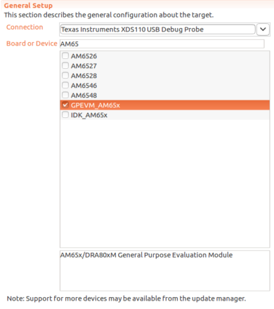
Fig. 7.1 CCS: Target Configuration
Load the initialization script of the DMSC_Cortex_M3_0 core with the AM65x Gels as shown below.
Open the Advanced tab of the target configuration file AM65x_EVM.ccxml
Gel files can be found at below path
${CCS_INSTALL_PATH}/ccs_base/emulation/boards/am65x/gel/AM65xEVM.gel
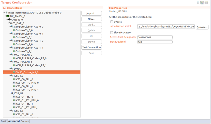
Fig. 7.2 CCS: Target Configuration Initialization Script
7.1.4.4.2. Prepare to Load RTOS/baremetal application binaries thru CCS
Note
When using CCS boot flow, please configure EVM in NOBOOT mode ( see No Boot Mode ) for connecting and loading binaries via CCS.
The launch.js file below is responsible to load and run the DMSC. It is also responsible to set the board configuration input for the DMSC. The board configuration is passed by the PDK example ${PSDK_RTOS_PATH}/pdk_am65xx_{version}/packages/ti/drv/sciclient/examples/sciclient_ccs_init executing on the MCU R5F core. The default board configuration is available for reference at ${PSDK_RTOS_PATH}/pdk_am65xx_{version}/packages/ti/drv/sciclient/soc/V1/sciclient_defaultBoardcfg.c
All PDK and SDK examples require the DMSC firmware to be executed.
GEL initialization
Open the launch.js script in an editor. Script is present in below path:
${PSDK_RTOS_PATH}/pdk_am65xx_{version}/packages/ti/drv/sciclient/tools/ccsLoadDmsc/am65xx/launch.js
${PSDK_RTOS_PATH} is the path to your PSDK RTOS installation, for example:
${HOME}/ti/
Edit the variable “pdkPath” with the absolute path of the pdk package, i.e ${PSDK_RTOS_PATH}/pdk_am65xx_{version}/packages
Open Code Composer Studio and launch the Target Configuration previously setup
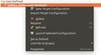
Fig. 7.3 CCS: Launch CCS Target Configuration
Go to the View Target configurations and launch a target configuration is done by right clicking on it.
Open the scripting console in CCS - Go to the View menu and then select Scripting Console
Load the launch.js script as shown below.
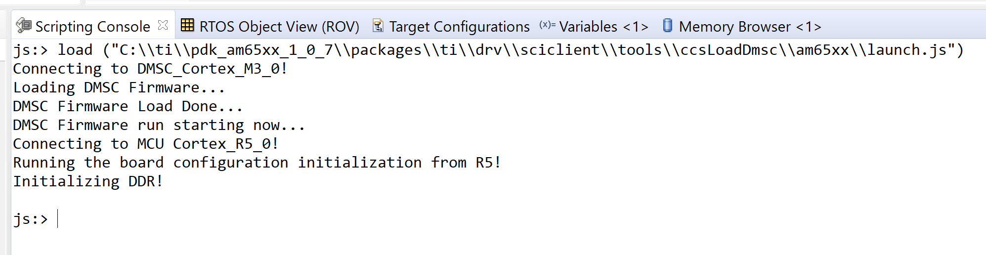
Fig. 7.4 CCS: Launch script
Wait till the script finishes. This step can take considerable time as it configures PLL etc. in the SOC via GEL files and configures DDR. This will connect to the MCU_Cortex_R5_0 core.
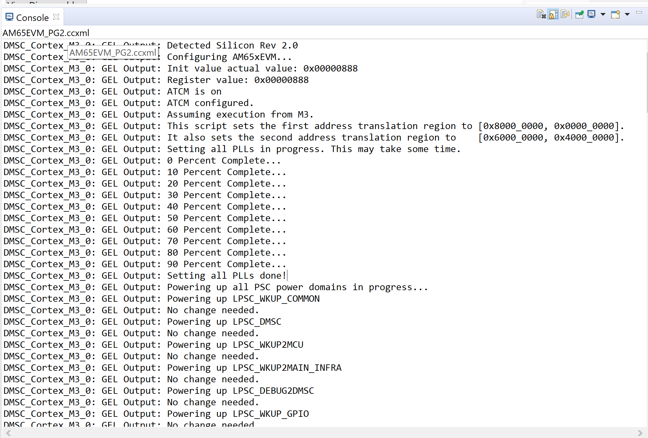
Fig. 7.5 CCS: Launch script
After script completes execution you should see below in Debug window
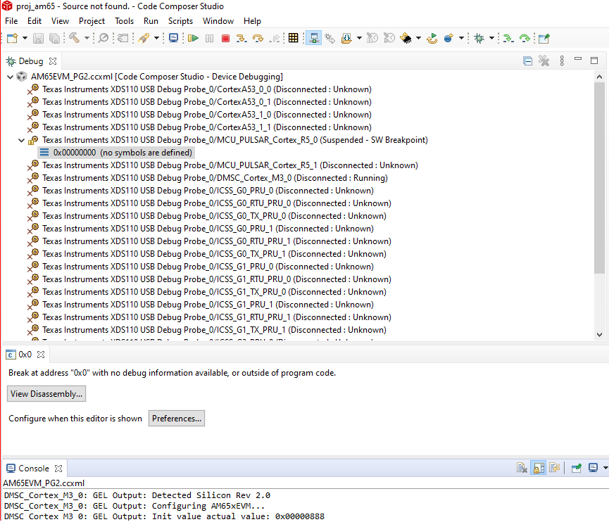
Fig. 7.6 CCS: Launch script Complete
7.1.4.4.3. Serial Connection to the Target
Set up the UART connection using the following host configuration in your favorite serial terminal program (e.g. Tera Term, screen, Minicom):
Baud Rate: 115200
Data Bits: 8
Parity: None
Flow Control: Off
7.1.4.4.4. Running the Application
Now that we are connected to the target, it is time to load the application. To do this, go to the Run –> Load –> Load Program menu in CCS. Then, click the Browse project… button and choose the [rtos or baremetal]_template_app_<board>_<core>.out executable. Then click OK to load the executable.
You should now see the main.c file open in CCS and the program halted at
the beginning of the main() function. At this point you can click on the
Resume (F8)  button to start executing the Template Application.
The application will begin running and print progress over the UART. You should see the following text printed to your serial terminal:
Board Init complete
Uart Init complete
I2C Init complete
Gpio Init complete
MCSPI Init complete
======== Peripheral Initialization complete ========

======== Starting to create application tasks ========

gpio_toggle_led_task task created.
uart_task task created.
spi_test_task task created.
i2c_eeprom_read_and_display_task task created.
======== Application tasks created successfully ========

gpio_toggle_led task started
uart_task task started

i2c_eeprom_read_and_display task started
spi_test task started
Board Name read: AM654PM_
Board version read: A.30
spi_test task ended
i2c_eeprom_read_and_display task ended
uart_task :Enter a word or Esc to quit >
Type a word into the serial terminal. It should be echoed back to you. Then,
enter the ESC character to exit the Template Application. For example:
uart_task :Enter a word or Esc to quit >hello
Data received is:hello

uart_task :Enter a word or Esc to quit >test
Data received is:test

uart_task :Enter a word or Esc to quit >^[

uart_task task ended
Template app ended
Next, click the Terminate  button to disconnect from the target.
At this point you have successfully imported, built, and run the Template
Application.
button to disconnect from the target.
At this point you have successfully imported, built, and run the Template
Application.
7.1.4.5. Task 5 - Examining the Template Application
Now that you’re familiar with using the Template Application, let us look into the code to see how it all works.
7.1.4.5.1. The main.c File
Begin by opening the main.c file. At the top of this file, after the
copyright header, there are a series of #include statements gathering
the necessary header files for the application:
/* Standard header files */
#include <string.h>

/* XDCtools Header files (RTOS only) */
#include <xdc/std.h>
#include <xdc/cfg/global.h>
#include <xdc/runtime/System.h>
#include <xdc/runtime/Error.h>

/* BIOS Header files (RTOS only) */
#include <ti/sysbios/BIOS.h>
#include <ti/sysbios/knl/Task.h>

/* Board header file */
#include <ti/board/board.h>

/* Local template app header file */
#include "app.h"
(RTOS only) XDCtools provides configuration tools to create and build a static configuration as part of your application. These headers are necessary for the
*.cfgconfiguration files.(RTOS only) BIOS is a synonym for TI-RTOS. These headers are necessary for accessing common RTOS features such as tasks.
The Board Library is a thin utility layer on top of CSL and other board utilities. It provides uniform Application Programming Interfaces (APIs) for all supported boards. It aims to assist the user to quickly write portable applications for supported boards by hiding board level details from the user.
The
app.hheader file includes header files for drivers used in the application code as well as macros and function prototypes. Specifically,app.hincludes headers for the following LLDs which are used by the application:/* Low level driver header files */ #include <ti/drv/gpio/GPIO.h> #include <ti/drv/uart/src/UART_utils_defs.h> #include <ti/drv/uart/UART_stdio.h> #include <ti/drv/uart/UART.h> #include <ti/drv/i2c/I2C.h> #include <ti/drv/spi/MCSPI.h>
Next, we come across the main() function which demonstrates the common
procedure for initializing an RTOS or bare-metal application. You can read the comments in
the code for further clarification. Let’s break down the steps:
Initialize the board:
Board_initCfg boardCfg;
boardCfg =
    BOARD_INIT_PINMUX_CONFIG |
    BOARD_INIT_MODULE_CLOCK |
    BOARD_INIT_UART_STDIO;
Board_init(boardCfg);
Intialize the peripherals:
UART_init();
I2C_init();
GPIO_init();
MCSPI_init();
(RTOS only) Create the application tasks. We will discuss this further in the section covering the
app.cfile.Start BIOS (RTOS) or start the application tasks directly (Bare-metal):
BIOS_start();

or

appRunTasks();
7.1.4.5.2. The app.c File
RTOS
Open the app.c file and take a look at the appTasksCreate()
function. You should recall that this function was called in step three
of main(). Inside of appTasksCreate() there are biosTaskCreate()
function calls for each peripheral task. biosTaskCreate() just wraps the
common task creation procudure into an easy-to-use function call. Navigate to
the bottom of the app.c file to check out biosTaskCreate().
The task creation procudure is as follows:
Create task variables
Task_Params taskParams;
Error_Block eb;
Task_Handle task;
Initialize
Error_BlockandTask_Paramsto their default valuesError_init(&eb); Task_Params_init(&taskParams);
Apply user arguments for stack name, priority, and stack size
taskParams.instance->name = taskName;
taskParams.priority = taskPriority;
taskParams.stackSize = stackSize;
Create the task
task = Task_create(taskFunctionPtr, &taskParams, &eb);
The tasks themselves are simply functions in your code following the format below:
void myTaskFunc(UArg arg0, UArg arg1)
Bare-metal
Open the app.c file and take a look at the appRunTasks() function.
Inside of appRunTasks() there are function calls for each peripheral task.
This file also contains setup code for a timer interrupt that controls
the LED blink task.
Note
The application functions are called “tasks” for naming consistency with the RTOS template application, but they are not actual SYS/BIOS tasks.
Next, let’s take a look at i2c_eeprom_read_and_display_task() to
see how to use TI Drivers. The procedure for opening a TI Driver generally
follows these steps:
Create driver handle and params structure
I2C_Handle      handle;
I2C_Params      params;
Initialize and set the driver parameters
I2C_Params_init(¶ms); params.transferMode = I2C_MODE_CALLBACK; params.transferCallbackFxn = someI2CCallbackFunction; // etc...
Open the driver
handle = I2C_open(someI2C_configIndexValue, ¶ms); if (!handle) { System_printf("I2C did not open"); }
For more information on TI Drivers, check out the included documentation for each driver at pdk_<platform>_<version>/packages/ti/drv/<driver>/docs.
For more infomation on SYS/BIOS, check out the User Guide at bios_<version>/docs.
7.1.4.6. Task 6 - Modifying the RTOS Template Application
Note
The instructions below apply to the RTOS Template Application only.
Now that you have an understanding of how to use the drivers and create RTOS tasks, let us make some simple modifications to create our own application.
We will create a simple application which allows the user to control the LED blink rate over the UART terminal. The user should be able to enter an LED blink period (between 0 and 5 seconds) and the user LED should blink at that rate.
This part of the lab is broken down into several sections. In each section, you will be given general instructions for modifications to make to the source files. After you make your own modifications they will be verified against provided code examples. Try to make the modifications on your own before looking at the answers!
7.1.4.6.1. Delete the Code You Don’t Need
The Template Application has tasks for UART, I2C, GPIO, and MCSPI drivers. Some of these tasks will not be used by our application. Go ahead and remove any tasks that you do not think you will need to create the application. Hold off on modifying tasks that will be reused until later steps.
Attention
Don’t peek! The next section will discuss answers to the task above.
Since our application is only consuming user input and blinking the LEDs, we only need the UART and GPIO tasks. That means the I2C and SPI tasks can be removed.
7.1.4.6.2. Add Support for Additional Features
Our application will require that the UART task has a way to communicate the delay value it receives from the user to the LED task to modify the blink rate. While this could be accomplished with something as simple as a shared global variable, TI-RTOS provides many other ways to accomplish inter-process communication. Take a look at the BIOS User Guide, which is bundled with the SDK at bios_<version>/docs/Bios_User_Guide.pdf for ideas on how to share data between tasks. After you decide on a method, you can use the API documentation located at bios_<version>/docs/Bios_APIs.html to figure out how to use the API in your application.
Attention
Don’t peek! The next section will discuss answers to the task above.
A good choice for passing the LED blink rate is the ti.sysbios.knl.Mailbox
module. This module can be used to pass buffers from one task to another on the
same processor.
To include Mailbox in your project you first need to add the module to the
app.cfg file:
var Mailbox = xdc.useModule('ti.sysbios.knl.Mailbox');
Next, you need to include the ti/sysbios/knl/Mailbox.h header file in
app.h:
#include <ti/sysbios/knl/Mailbox.h>
To create a Mailbox, use the Mailbox_create() API which is defined below:
Mailbox_Handle Mailbox_create(SizeT             bufsize,
                              UInt              numBufs,
                              Mailbox_Params    *params,
                              Error_Block       *eb)
You are now set up to use Mailbox in your application code.
7.1.4.6.3. Add New Application Code
Modify the existing UART and LED task code to functions for the new application. If you run in to any issues, make sure to use CCS debug features such as breakpoints and variable watching to verify that the application is functioning in the way that you expect. Functional example code for the AM572x EVM will be provided at the end.
Attention
Don’t peek! The next section will discuss answers to the task above.
Create a global
Mailbox_Handleto be shared by theuart_task()andgpio_toggle_led_task(). Then create a Mailbox at the end of theappTasksCreate()function.Modify the
uart_task()code to scan for an unisgned integer delay value instead of a string. This value should then be placed in the Mailbox by using theMailbox_post()API.Modify
gpio_toggle_led_task()to retrieve a delay value from the Mailbox via theMailbox_pend()API. This delay value should be used in thetask_sleep()function calls.
Now, give your project a try. You should be able to type in LED delay values to
the UART terminal and see the blink rate of the LED change accordingly. To see
a functioning solution, you can download the modified source files from the
links below. Sections of the source files that were modified from the originals
are marked with a /* Modification: */ comment.
7.1.5. Additional Information
7.1.5.1. Porting to a Custom Board
The Template Application can be easily modified to run on a custom board. The
major change required is to link in a new Board Library. Modifying the
Template Application for your custom Board can be achieved by simply removing
the ti.board library and PATH from the project and replacing with your
specific board libraty and PATH under the linker build options in CCS by
right clicking on the project and selecting
Properties –> GNU Linker –> Libraries.
For example, currently the library linked for AM65xx is specified in the .projectspec file as follows:
linkerBuildOptions=
    -L${TI_PDK_INSTALL_DIR}/packages/ti/board/lib/am65xx_evm/a53/release/
    -l:ti.board.aa53fg
Note
Currently for AM65xx EVM there is also a dependemcy on the GPIO_evmAM65xx_board.c and GPIO_board.h files. These files can be modified for your custom board.
7.1.6. Next Steps
Thanks for taking the time to read through this getting started workshop. At this point you should be comfortable with the basic structure of the SDK, know how to import, build, modify, and run applications on the target, and know where to find various documentation in the SDK and Software Developer Guide.
Next, you can check out our various video training series in the TI training portal and get started writing your own application!
If you have any questions along the way please remember to reach out to our engineers on the E2E forums.