6.1. Host
6.1.1. How to Develop with 3D Graphics
Please refer to Graphics & Display chapter for details.
6.1.2. How to Develop accelerated Multimedia using GStreamer on AM57xx
Please refer to Multimedia chapter for details.
6.1.3. How to Build a Ubuntu Linux host under VMware
Warning
This content is no longer maintained. It has been left here in case it can help someone, but it will not be maintained and will eventually move out of date. If you choose to use a Virtual Machine to host your development version of Linux on a PC, the VM provider will provide up to date information that is better and more complete than what we’ve provided here.
Introduction
This guide demonstrates how to get a virtual Ubuntu Linux machine running with VMware under Windows 7. Please use only the 32-bit Ubuntu 14.04 release as this is what is called an LTS (Long Term Support). There are SDK scripts that will be checking for this release identity.
Requirements:
- Windows 7 host with internet connection, at least 1G of RAM and 40G of free hard drive space.
The instructions here are for setting up a 40G virtual machine. The entire 40G is not taken at once, but as the machine is used and software is installed, the machine can grow and take up as much as 40G.
Download the Ubuntu 14.04 LTS ISO image
Get the Ubuntu 14.04 LTS CD ISO image from: https://releases.ubuntu.com/14.04/. Select PC (Intel x86) desktop CD under the Desktop CD section.
Click download and the follow instructions to download and save the ISO image somewhere. Remember where you save this - you will need the ISO soon!(CD image).
Download VMware and install
Get VMware from: https://www.vmware.com
Vmware Player is a free download from the website and enables the user to create an entire virtual machine from scratch using just the ISO image downloaded from Ubuntu. It is necessary to sign up for an account at VMware in order to get to the download areas. The general steps to getting VMware are as follows:
- Login to the vmware website
- Select VMware Player from the products menu
- Follow the steps to download VMware Player
NOTE - We have tested with v7.0.0 with no known issues. As of Feburary, 2015, v7.0.0 is the latest version.
- Run the executable to install VMware
- Accept license and all default settings.
Create a New Virtual Machine with VMware
Before starting a new installation it is assumed that the Windows host has a proper internet connection to a DHCP server and that the Windows host has enough hard drive space for the new virtual machine.
The following steps are performed with VMware 7.0.0. The exact steps with other versions may vary slightly
- Start VMware.
- From the File menu select “Create a New Virtual Machine...”
- Choose to install the operating system later. Click “Next”.
- Select Linux as the “Guest Operating System” and then choose Ubuntu as the “Version”. Click “next”.
- Provide a “Virtual machine name” and “Location” where the machine will be stored on the Windows host. The defaults are fine here. Click “Next”.
- For “Maximum disk size (GB)” it is good to start with 40G if possible. This means that it will take up 40G on the Windows host. Make sure that the Windows host has at least this much before proceeding. It is also a good practice to tell VMware to split the virtual disk into 2G files. This will makes the image easier to copy and transport if necessary. Click “Next”.
- Click “Finish” to complete the creation of the virtual machine.
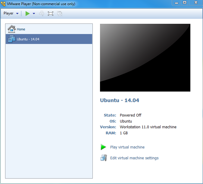
The machine name will now be listed under the home page of VMware. It is necessary to modify some machine settings before playing the machine for the first time. Select the machine in the home page and then click on “Edit virtual machine settings” on the right.
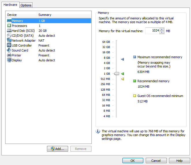
Click on CD/DVD and change the connection to “Use ISO image file”. Click on “Browse...” and select the Ubuntu ISO image file that was previously downloaded. Click on Network Adapter and change the Network connection to “Bridged” and then check the box to “Replicate physical network connection state”.
Adding a serial port to the virtual machine
If you plan to use a serial terminal application, a serial port must be added to the virtual machine. This port must be a physical serial port which exists on the host PC. Click on “Add...” and select “Serial Port”. Click “Next”. Choose “Use physical serial port on host”. Click “Next”. Click Finish. Click “Ok”.
Since this is a physical port on the host PC, it cannot be used by the host PC and the virtual machine at the same time. When the virtual machine is started, the serial port will be unavailable for use by the host PC. If the serial port is being used at the time that the virtual machine is started, the virtual machine will not be able to access the serial port after it is booted up. So if you want the virtual machine to gain control of the physical serial port of the host PC, there can not be any application like hyperterminal or teraterm running on the host PC at the time that the virtual machine is started.
Further instructions for using the serial port with minicom inside of Ubuntu are here.
Now click on “Play virtual machine”. Since this is the first time starting the machine and the Ubuntu ISO image is in the virtual CD drive, the Ubuntu OS will install itself in the virtual machine.
Click through the Ubuntu installation, making the appropriate choices as you go. This will help with SDK installation scripts.
After the machine reboots into Ubuntu it is helpful to take the Ubuntu ISO out of the virtual CD drive. Click on the VM menu and select “Settings...”. Click on CD/DVD and change the connection from “Use ISO image file” to “Use physical drive”. The actual drive letter can be selected from the drop down list. If there is no physical drive on the host machine, the CD/DVD device can be simply removed from the machine.
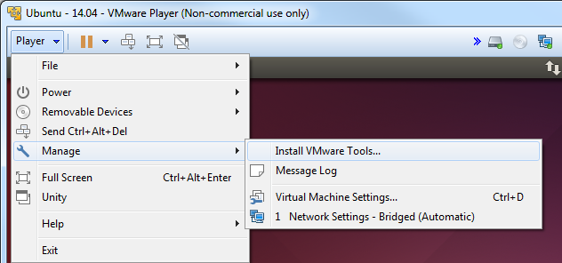
Install VMware Tools
VMware tools is a very useful addition to VMware. It allows you to resize the VMware screen ,cut-and-paste of text and drag and drop files from the Ubuntu machine to and from the Windows host.
Within the virtual machine window click the Player -> Manage -> Install VMware Tools
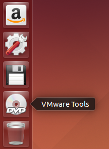
The VMware tools are contained in an ISO image that VMware will automatically mount. This drive will show up on the Ubuntu desktop as if it were a disk in a DVD drive.
There will be a single tarball on the drive named VMwareTools-9.9.0-2304977.tar.gz (or with a slightly different version number). Extract the tarball somewhere in your /home/<user> directory. You will see that a vmware-tools-distrib folder was created and a file name vmware-install.pl inside. Execute vmware-install.pl to install VMware Tools. The Perl script must be executed as a super-user. This is done in Ubuntu by pre-pending the command with “sudo”. When prompted for a password, enter the password for the user account. In Ubuntu, there is no “root” account. However, the first user account created when Ubuntu is installed can become a super-user with the “sudo” command. Select all of defaults during installation of VMware Tools.
An example is shown below.
sitara@sitara-virtual-machine:~$ cd
sitara@sitara-virtual-machine:~$ tar -xzvf /media/sitara/VMware\ Tools/VMwareTools-9.9.0-2304977.tar.gz
sitara@sitara-virtual-machine:~$ sudo ./vmware-tools-distrib/vmware-install.pl
Confirming a Valid Network Connection
After logging into the machine for the first time, bring up a terminal window. This can be found under the Applications menu in Ubuntu. Applications –> Accessories –> Terminal. Type pwd in this terminal. This should return /home/<user>. Now type ifconfig. This should return information about the network connection. Under eth0 the IP address should be similar (but not the same) as the IP address owned by the Windows host.
sitara@sitara-virtual-machine:~$ ifconfig
eth0 Link encap:Ethernet HWaddr 00:0c:29:da:a8:6e
inet addr:128.247.107.65 Bcast:128.247.107.255 Mask:255.255.254.0
inet6 addr: fe80::20c:29ff:feda:a86e/64 Scope:Link
UP BROADCAST RUNNING MULTICAST MTU:1500 Metric:1
RX packets:759 errors:0 dropped:0 overruns:0 frame:0
TX packets:32 errors:0 dropped:0 overruns:0 carrier:0
collisions:0 txqueuelen:1000
RX bytes:62873 (62.8 KB) TX bytes:4937 (4.9 KB)
Interrupt:19 Base address:0x2024

lo Link encap:Local Loopback
inet addr:127.0.0.1 Mask:255.0.0.0
inet6 addr: ::1/128 Scope:Host
UP LOOPBACK RUNNING MTU:16436 Metric:1
RX packets:12 errors:0 dropped:0 overruns:0 frame:0
TX packets:12 errors:0 dropped:0 overruns:0 carrier:0
collisions:0 txqueuelen:0
RX bytes:720 (720.0 B) TX bytes:720 (720.0 B)
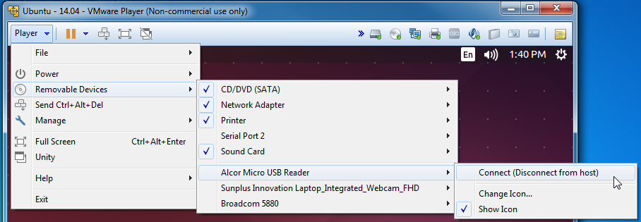
How to Read a USB SD Card Reader in VMware
6.1.4. Connect to an EVM via Telnet
Using Telnet
The initialization file (/etc/init.d/rcS) starts a telnet server. If your development host is in the same sub-net as the EVM, you can telnet to it using the IP address assigned in the U-boot environment. The following is an example from a Linux host.
$ telnet 192.168.1.10
You will be prompted for a user name and password. The user name should be root and the password should be left blank (just hit Enter).
From a Windows XP host, click the Start button, then click Run... Type telnet and click OK. This will open a telnet window.
Type “o < ip-addr >” and hit enter. Example:
Microsoft Telnet> o 128.247.107.12
Type root for the password and leave the password blank (just hit Enter)
6.1.5. How to Setup a Samba Server
Introduction
When using a Virtual machine you may share files & folders via the Share Foldr feature of that partoicular Virtual Machine. Another alternative, especially if you are using a dedicated Linux host, is to configure a Samba server on your Linux host.
Samba allows a host to interact with a Microsoft Windows client or server as if it is a Windows file and print server. In other words, if you are installing software on a Windows machine, you can easily transfer/modify files to the host machine by accessing it (the host machine) through windows.
Installing a Samba Server
1. Samba can be installed by opening a terminal. (Applications -> System Tools -> Terminal)
2. Switch to root user by typing su and entering the password you set during the install.
- On Fedora install Samba with the yum command: system-config-samba
- Open the Samba GUI (System -> Administration -> Samba).
- Configure the share
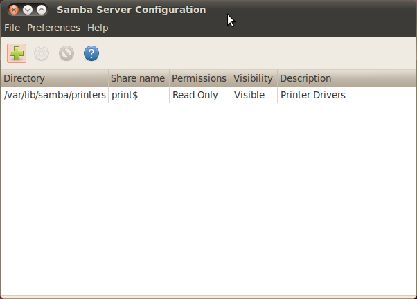
- Click on “Add Share”
- Specify the directory you want to share. For example, /home/<username>
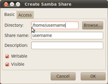
- Check both the Writable and Visable boxes
- On the “Access” tab, select the Allow access to everyone option
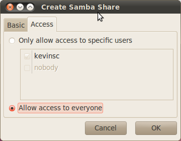
- Select “OK”
- Set up the workgroup
- From the toolbar, select Preferences -> Server Settings
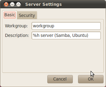
- Specify the “Workgroup” to match the workgroup on your Windows environment
- Select “OK”
- Add a user
- From the toolbar, select Preferences -> Samba Users
- Click “Add User”
- From the “Unix Username” dropdown box, select the username you set up
- In the “Windows Username” and password boxes, enter the Unix Username and password for that user, respectively.
- Select “OK”
- Turn off the firewall
- System -> Administration -> Firewall
- Select the “Disable” button
NOTE - If you are within your company’s firewall you may need to configure the network proxy.
- Enable the Samba and NFS services
- System -> Administration -> Services (NOTE - Not available in Ubuntu 10.04 LTS. However the Samba service should start automatically)
- Enable the services by browsing through the list on the left and locating nfs and smb. If they are not already enabled, enable them by clicking the “Enable” button.
- Test the configuration
- From a terminal on the Linux workstation, type the command <prompt> ifconfig and note the IP address
- From your Windows machine, go to Start -> Run and type \\<IP_ADDR> replacing <IP_ADDR> with the IP address of the Linux system
6.1.6. Boot Sequence
Introduction
This page describes the boot sequence of an OMAP3 EVM.
General Boot Sequence (Linux system)
Boot sequence (in order)
- Boot ROM
- X-loader
- U-boot
- Linux
At power-up an OMAP3 device begins booting from internal Boot ROM. This code is fixed during the manufacturing process and cannot be altered. The Boot ROM reads boot configuration pins (SW4 on the OMAP3 EVM) which tell the Boot ROM where to look for the first external bootloader. The choices include NAND, UART, and SD/MMC Card. Control is then passed to this first external bootloader called x-loader. The x-loader application is included in the Linux PSP provided by TI and can be modified by the end user. The x-loader application passes control to u-boot. U-boot is also a bootloader and is considered the second external bootloader in this case.
U-boot is the application which passes control to the Linux system. The main goal of u-boot is to retrieve the Linux kernel and provide the kernel with information about the location of the Linux filesystem. U-boot can be configured to retrieve the kernel from NAND, SD/MMC Card, UART or Ethernet (via TFTP). U-boot can also specify a root filesystem that is located in NAND (jffs2), SRAM (ramdisk), SD/MMC card (ext3 partition) or mounted over IP (NFS).
U-boot then boots the Linux kernel. The Linux kernel mounts the Linux root filesystem.
Booting TI SDK
The OMAP3 EVM which includes the TI SDK will come with an SD card. This card has been formatted and partition in such a way that the entire system comes from this card. There is a bootable FAT partition which contains x-loader (MLO), u-boot (u-boot.bin )and the Linux kernel (uImage). There is a separate ext3 partition which contains the Linux root filesystem.
A tutorial for making this SD card can be found here:
The actual file names of the binaries on the FAT partition will be as follows:
| Application or Script | Actual Filename on SD card |
|---|---|
| X-loader | MLO |
| U-boot | u-boot.bin |
| Linux kernel | uImage |
| boot script | boot.scr |
Table: Files on boot (FAT) partition of SD card
When booting from an SD card, the OMAP3 Boot ROM code will search the SD card for the filename “MLO” when looking for x-loader.
To boot from this SD card, the switches on SW4 should be set to SD/MMC boot.
- SW4 = 00100111 (high to low, i.e. SW4.1 = 1)
- 1 = “On” position on the switch
Texas Instruments X-Loader 1.45 (Mar 19 2010 - 19:44:19)
Starting X-loader on MMC
Reading boot sector

212504 Bytes Read from MMC
Starting OS Bootloader from MMC...
Starting OS Bootloader...
X-loader then passes control to u-boot. U-boot expects to find “environment variables” in NAND flash. When a board is booted for the first time or if the NAND has been erased, u-boot will indicate a Warning about bad NAND. U-boot will write a default environment that it will then use to continue the boot process.
U-Boot 2009.11 (May 06 2010 - 16:57:54)

OMAP34xx/35xx-GP ES1.0, CPU-OPP2 L3-165MHz
OMAP3 EVM board + LPDDR/NAND
I2C: ready
DRAM: 128 MB
NAND: 256 MiB
*** Warning - bad CRC or NAND, using default environment

In: serial
Out: serial
Err: serial
Read back SMSC id 0x92200000
Die ID #731c0000000000000156087c0a023021
Net: smc911x-0
Hit any key to stop autoboot: 0
The default environment is designed to boot the Linux system from the SD card, so it is not necessary to stop the boot process. And the next time that the EVM is booted the default environment will exist in NAND so the “bad NAND” warning will not be displayed.
U-boot allows the user a 2-3 seconds window to stop the boot process. Hit any key in the UART terminal application and the u-boot prompt will be displayed as shown below:
OMAP3_EVM #
There are several useful commands to remember here. To display the environment variables, type “printenv” or just “pri”.
OMAP3_EVM #
OMAP3_EVM # printenv
bootcmd=if mmc init; then if run loadbootscript; then run bootscript; else if run loaduimage; then run mmcboot; else run nandboot; f
i; fi; else run nandboot; fi
bootdelay=2
baudrate=115200
bootfile=uImage
loadaddr=0x82000000
usbtty=cdc_acm
console=ttyS0,115200n8
mmcargs=setenv bootargs console=${console} root=/dev/mmcblk0p2 rw rootfstype=ext3 rootwait
nandargs=setenv bootargs console=${console} root=/dev/mtdblock4 rw rootfstype=jffs2
loadbootscript=fatload mmc 0 ${loadaddr} boot.scr
bootscript=echo Running bootscript from mmc ...; source ${loadaddr}
loaduimage=fatload mmc 0 ${loadaddr} uImage
mmcboot=echo Booting from mmc ...; run mmcargs; bootm ${loadaddr}
nandboot=echo Booting from nand ...; run nandargs; onenand read ${loadaddr} 280000 400000; bootm ${loadaddr}
stdin=serial
stdout=serial
stderr=serial
dieid#=731c0000000000000156087c0a023021
ethact=smc911x-0

Environment size: 873/131068 bytes
OMAP3_EVM #
OMAP3_EVM # boot
## Booting kernel from Legacy Image at 80000000 ...
Image Name: Linux-2.6.32
Image Type: ARM Linux Kernel Image (uncompressed)
Data Size: 2396212 Bytes = 2.3 MB
Load Address: 80008000
Entry Point: 80008000
Verifying Checksum ... OK
Loading Kernel Image ... OK
OK

Starting kernel ...

Uncompressing Linux.....................................................................................................
.................................................. done, booting the kernel.
dm3730-am3715-evm login:
Closer Look At bootcmd
The bootcmd environment variable is a set of nested conditional statements.
bootcmd=if mmc init; then if run loadbootscript; then run bootscript; else if run loaduimage; then run mmcboot; else run nandboot; f
i; fi; else run nandboot; fi
6.1.7. Moving Files to the Target System
Introduction
This guide discusses how applications or other files can be moved to the target file system of the EVM.
File System on SD card
The SD card which comes with the TI SDK has a Linux ext3 partition that is used as the target file system. This partition is readable from a Linux host. In Ubuntu 10.04 this partition will be mounted on /media/rootfs when the card is used with an SD card reader inserted into a USB port on the Ubuntu host.
When the SD card is mounted with a card reader in the Linux host it is possible to perform “cp” commands from the host into sub-directories under /media/rootfs or just use a browser window to drag and drop the files from the host to the SD card.
Switching the SD card back and forth from the EVM to the SD card reader is time consuming during development. Using a NFS during development is the preferred method and makes moving files between the host and target trivial.
File System on Network File System (NFS)
When the target file system is served from the Linux development host machine it is trivial to move files between the host and target. The NFS directory is set up on the host machine by the SDK installer. The default location in the Ubuntu 10.04 development environment is /home/user/ti-sdk-AM3715-evm-4.0.0.0/filesystem. This could vary depending on the version of the SDK and how it was installed. An “ls -l” of this directory in the host system will show what will be the root directory of the target when it boots up.
user@U1004GT:~/ti-sdk-AM3715-evm-4.0.0.0/filesystem$ pwd
/home/user/ti-sdk-AM3715-evm-4.0.0.0/filesystem
user@U1004GT:~/ti-sdk-AM3715-evm-4.0.0.0/filesystem$ ls -l
total 60
drwxr-xr-x  2 root root 4096 2010-05-07 07:51 bin
drwxr-xr-x  2 root root 4096 2010-05-07 00:30 boot
drwxr-xr-x  2 root root 4096 2010-05-05 16:28 dev
drwxr-xr-x 24 root root 4096 2010-05-14 10:46 etc
drwxr-xr-x  3 root root 4096 2010-05-07 00:29 home
drwxr-xr-x  4 root root 4096 2010-05-07 00:30 lib
lrwxrwxrwx  1 root root   12 2010-05-13 09:35 linuxrc -> /bin/busybox
drwxr-xr-x 13 root root 4096 2010-05-14 11:01 media
drwxr-xr-x  2 root root 4096 2010-05-07 00:29 mnt
drwxr-xr-x  2 root root 4096 2010-05-05 16:28 proc
drwxr-xr-x  2 root root 4096 2010-05-07 07:51 sbin
drwxr-xr-x  2 root root 4096 2010-05-07 07:51 Settings
drwxr-xr-x  3 root root 4096 2010-05-07 00:29 srv
drwxr-xr-x  2 root root 4096 2010-05-05 16:28 sys
lrwxrwxrwx  1 root root    8 2010-05-13 09:35 tmp -> /var/tmp
drwxr-xr-x 10 root root 4096 2010-05-07 08:43 usr
drwxr-xr-x  7 root root 4096 2010-05-04 21:54 var
user@U1004GT:~/ti-sdk-AM3715-evm-4.0.0.0/filesystem$
So from the perspective of the host, the target filesystem is just a sub-directory of the host. If the file is in ./filesystem on the host, then the same file will show up in the root directory of the target after the target boots into the NFS. And if the file is in a subdirectory of ./filesystem (example ./filesystem/sub-dir) then it will show up in the /sub-dir directory of the target after the target boots into the NFS.
The top level makefile of the TI SDK supports an install target that will copy applications into the NFS of the SDK. See the README file at the top level of the SDK for information about the install target.
6.1.8. How to Flash Linux System from U-boot
Application
This article applies to Sitara SDK 4.0.1 which uses the Platform Support Package (PSP) software version 03.01.00.06
for AM35x and AM37x devices. This information is obsolete as newer software has different NAND ECC requirements.
Introduction
This guide will show how use u-boot to flash the NAND of an OMAP3 EVM (for AM37x, DM37x or OMAP35xx devices) or an AM3517EVM (for AM35x devices) with Linux system binaries.
- Assumptions:
- SD card with system binaries (x-loader, u-boot, Linux kernel) on boot partition
- Linux root filesystem in rootfs partition of SD card or root filesystem available via NFS
Caution
The procedures here will erase the NAND flash of the EVM. This includes all u-boot environment variables. Use the “printenv” command (or just “pri”) in u-boot to print a complete list of environment variables. Copy and paste these to a text file for safe keeping.
Boot EVM into SD/MMC card boot mode
The SD card must at least have the files MLO, u-boot.bin, and uImage. All of these files can also be found in the ”./psp/prebuilt-images” directory in the Sitara SDK installation (with names that include the platform name and software revision info). The MLO file is simply a re-named copy of the file x-load.bin.ift that is produced by rebuilding x-loader and signing the file. When the board is booted in SD/MMC card boot mode, the ROM code looks specifically for the file with the name MLO as the primary bootloader.
To boot from this SD card, the boot switches should be set to SD/MMC boot:
For Mistral OMAP EVM (AM37x, DM37x or OMAP35xx devices)
Start the board and interrupt the boot process when prompted by hitting any key in the UART terminal application:
Texas Instruments X-Loader 1.45 (Mar 19 2010 - 19:44:19)
Starting X-loader on MMC
Reading boot sector

212504 Bytes Read from MMC
Starting OS Bootloader from MMC...
Starting OS Bootloader...
U-Boot 2009.11 (May 06 2010 - 16:57:54)

OMAP34xx/35xx-GP ES1.0, CPU-OPP2 L3-165MHz
OMAP3 EVM board + LPDDR/NAND
I2C: ready
DRAM: 128 MB
NAND: 256 MiB
*** Warning - bad CRC or NAND, using default environment

In: serial
Out: serial
Err: serial
Read back SMSC id 0x92200000
Die ID #731c0000000000000156087c0a023021
Net: smc911x-0
Hit any key to stop autoboot: 0
OMAP3_EVM #
OMAP3_EVM #
All of the commands in this guide are performed at the u-boot prompt.
Run the u-boot commands to flash the NAND
All of the following commands are performed at the u-boot prompt.
These commands are actually a series of u-boot commands that are connected together with semicolons. The individual commands can be entered separately or simple pasted from here.
- Complete xloader write from MMC to NAND (only erases one block=128k).
mw.b 0x81600000 0xff 0x20000;nand erase 0 20000;mmc init;fatload mmc 0 0x81600000 x-load.bin.ift;nandecc hw; nand write.i 0x81600000 0 20000
- Complete uboot write from MMC to NAND (only erases two blocks=256k)
mw.b 0x81600000 0xff 0x40000;nand erase 80000 40000;mmc init;fatload mmc 0 0x81600000 u-boot.bin;nandecc sw; nand write.i 0x81600000 80000 40000
- Complete kernel write from MMC to NAND (erases 3M)
mw.b 0x81600000 0xff 0x1400000;nand erase 280000 300000;mmc init;fatload mmc 0 0x81600000 uImage;nandecc sw; nand write.i 0x81600000 280000 300000
Put the EVM in NAND boot mode
With the EVM in NAND boot mode and the images flashed in NAND as detailed above, the SD card does not need to be in the EVM at boot up. X-loader and u-boot will run from NAND. In order to also pull the Linux kernel (uImage) from NAND it will be necessary to halt the boot process and edit some u-boot environment variables.
For Mistral OMAP EVM (AM37x, DM37x or OMAP35xx devices)
Set SW4 switches #2, #4 and #6 to the ON position and all others OFF (NAND, UART3 boot order)
For LogicPD AM3517EVM (AM35x device)
Set SW7 with switches #1 thru #8 all to the OFF position. (NAND, EMAC, USB, MMC1 boot order)
- Save off the original boot command
setenv bootcmd_original ${bootcmd}
saveenv
- Create command for reading the kernel from NAND and then another command for doing the boot where the kernel is pulled from NAND and the root filesystem is from the SD/MMC card.
setenv nand_kernel 'nand read.i ${loadaddr} 280000 300000'
setenv nand_mmc_boot 'run nand_kernel;setenv bootargs ${mmcargs}; bootm'
Run this last command to actually perform the boot. And always save the environment after making changes.
saveenv
run nand_mmc_boot
Flashing the Root File System to NAND
A jffs2 file system can be copied into NAND flash. Copy the file rootfs.tar.gz to the /home/root directory on the SD Card. Boot the EVM to Linux and enter the following commands:
[prompt]$ flash_eraseall –j /dev/mtd4
[prompt]$ mount /dev/mtdblock4 /media/nand –t jffs2
[prompt]$ cd /media/nand
[prompt]$ tar xzf /home/root/rootfs.tar.gz
[prompt]$ reboot –f
The bootargs under u-boot must be altered to use this new NAND file system.
NOTE:After the reboot the board is now running in u-boot, remember to stop the autoboot sequence by typing any key. The following are u-boot commands:
setenv bootargs 'mem=128M console=ttyS0,115200n8 noinitrd root=/dev/mtdblock4 rw rootfstype=jffs2 ip=dhcp'
bootm
Mounting File System from NFS
The file system can also be mounted as a Network File System (NFS). The NFS is simply a sub-directory of the Linux host development system.
Another command can be made to pull the root filesystem via NFS. This command can be combine with the one to pull the bootloaders and kernel from NAND. (The IP address and path to the NFS is an example and should be changed by the user).
setenv serverip <ip address of nfs host>
setenv nfsargs 'setenv bootargs mem=128M console=ttyS0,115200n8 noinitrd rw ip=dhcp root=/dev/nfs nfsroot=${serverip}:/home/user/ti-sdk-AM3715-evm-4.0.0.0/rfs,nolock,rsize=1024,wsize=1024'
setenv nand_nfs_boot 'run nand_kernel;run nfsargs; bootm ${loadaddr}'
saveenv
run nand_nfs_boot
Default NAND partitioning (from x-loader)
- Block size = 0x00020000 (128k) * Page size = 0x00000800 (2k) */
6.1.9. Preventing BeagleBone board reset on JTAG Connect
6.1.10. Customizing the SDK Splash Screen
Overview
This article discusses how to customize the splash screen for the Linux SDK. The info was derived from this e2e forum post.
Steps
The “psplash” user space application is called at boot time, showing the TI logo splash screen. In order to change the displayed image, you need to first download the “psplash” package source code from here. The next steps are as follows:
1. Use the ./make-image-header.sh script included in the package to create a new header file with your new image: (you need to install libgdk-pixbuf2.0-dev library first)
./make-image-header.sh <path_to_image_file> <NAME>
Note: The <NAME> argument can be whatever you want it to be, but for the fastest approach you should use “POKY” as this is what is used by default in the psplash.c file. Unfortunately this isn’t configurable and you have to edit the file manually if you wish to use different name.
- The above command will generate the header file with the image contents (<your_logo_filename>-img.h).
- Open the psplash.c file and replace the file name in the following line at the top of the file:
#include "psplash-poky-img.h"
with
#include "<your_logo_filename>-img.h"
2.Export the needed variables and then configure and build psplash:
export CROSS_COMPILE=arm-linux-gnueabihf-
export ARCH=arm
export PATH=$PATH:$HOME/ti-sdk-am335x-evm-06.00.00.00/linux-devkit/sysroots/i686-arago-linux/usr/bin
./autogen.sh --host=arm-linux CC=arm-linux-gnueabihf-gcc
make
3. Replace the /usr/bin/psplash file in your root file system with the generated psplash file.
6.1.11. AM335x ICEv2 flash erase
Introduction
The AM3359 ICE development board from Texas Instruments comes pre-loaded with a default application in the on-board SPI flash device. In order to boot Linux from the SD card you will need to clear the SPI flash so that the boot process will fall back to SD card boot mode. The following steps will clear the SPI flash. I performed these steps with CCS v6.1.3 on a Ubuntu 14.04 host system
Steps
Mare sure pins 1 and 2 of Jumper J5 (sysboot) are connected on the board
Make sure that USB cable is connected from the AM3359 ICE board to your host development machine
Launch Code Composer Studio (CCS)
- If you do not have CCS, download it here: CCS Download
Create a target configuration file in CCS to connect to the AM3359 ICE board
NOTE If you already have a target configuration for your AM3359 ICE board you may skip this step
- Click File -> New-> Target Configuration File
- Filename : AM3359-ice-v2.ccxml. Check “Use shared location” to be
available to anyone who uses the workspace. Click Finish. A window
opens up which is to configure the connection details
- Connection: “Texas Instruments XDS100v2 USB Debug Probe”
- Device: ICE_AM3359
- Click Save
Launch your AM3359 ICE Target Configuration
- Click Window -> Show View -> Target Configurations
- Right click on the AM3359-ice-v2.ccxml file and the click Launch Selected Configuration
- This should switch your current perspective to the CCS Debug perspective. If it doesn’t, click View -> Debug to get to the CCS Debug perspective
Connect the debugger to the CortexA8 core
- Right click on Texas Instruments XDS100v2 USB Debug Probe_0/CortxA8 listed in the Debug view and select Connect Target
Load the SPI flash programmer into the CortexA8 core
- Download the SPI flash programmer and unzip it: File:Isdk spi flasher.zip
- Highlight the Texas Instruments XDS100v2 USB Debug Probe_0/CortxA8 by clicking on it
- Click Run -> Load -> Load Program
- Browse to the isdk_spi_flasher.out file (that you just downloaded and unzipped) and click OK
Run the SPI flash programmer on the CortexA8
- Highlight the Texas Instruments XDS100v2 USB Debug Probe_0/CortxA8 by clicking on it
- Click Run -> Resume
At this point the SPI flash programmer is running on the CortexA8 and we just need to follow the prompts to clear the flash
- If it isn’t opened already, open the Console view by clicking Window -> Show View -> Console
- The program will give you the following prompts, type the
responses and press Enter
- Enter Operation [1 - Flash ] [2 - Erase] : 2
- Enter the offset [in Hex]: 0
- Enter size to be erased in Kilo bytes: 64
Once the program outputs ‘Erase complete. Exiting’ then you are finished! You can now disconnect the debugger and close CCS. Then, power down the board, and connect back pins 2 and 3 on Jumper J5 (sysboot). After that, you can put your SD card loaded with Linux into the ICE board and reset it to boot Linux.
6.1.12. Ubuntu 14.04 Set Up to Network Boot an AM335x/AM437x Based Platform
The AM335x/AM437x processor families from Sitara can boot from the ROM Bootloader (RBL) using the BOOTP networking protocol that is supported by many standard tools. This capability allows developers to set up an environment where the U-Boot bootloader, Linux kernel, and even filesystem can be hosted from the development Linux box, using only a ethernet cable or even USB cable depending on the capabilities of the AM335x/AM437x based target system. This process sets up a very nice, efficient Linux development system where changes to U-Boot, the Kernel, or even the filesystem can be quickly tested for fast, iterative development.
This page describes how to set up an Ubuntu 14.04 based Linux Development host as a BOOTP server that will work well with the AM335x/AM437x RBL and U-Boot. While the specific steps and tools may be a bit different, the information provided should be enough to set up most Linux distributions. This set up assumes a fresh Ubuntu install and should include everything needed to get up to a U-Boot command prompt. From here, a variety of next steps can be used to acheive the desired Linux environment on the target (for example, setting up a Network File System (NFS) for filesystem development) or using an initramfs.
In order to get to a simple U-Boot command prompt, the following tools will be needed:
- Ubuntu 14.04 (instructions assume a fresh install for simplicity)
- A BOOTP/DHCP server - isc-dhcp-server is used, but others work as
well
- The server has to be configured to respond properly to the BOOTP requests from the AM335x/AM437x device
- A TFTP Server - atftpd is used, but others work as well
- A method to start/stop services - xinetd is used here
- A Hardware platform that can be set to boot from either Ethernet or USB RNDIS (this guide uses the Beaglebone Black as an example)
- A U-Boot image that includes the necessary peripheral booting support (Ethernet or USB RNDIS) often provided with SDK pre-builts
- The necessary cables and such to get everything hooked up appropriately
6.1.12.1. Step By Step
Here is the process to follow to get everything up and running. Most of the steps necessary are the same whether using Ethernet or USB. But, for USB there are some additional steps required.
Install Ubuntu 14.04 (preferably on a dedicated PC).
Note
Other versions of Ubuntu and other distributions will likely need small changes to configure this process correctly.
The Processor SDK for Linux provides a working Linux system for development (bootloader, kernel, filesystem and toolchain). This process should work with theoretically any system properly ported and configured for AM335x/AM437x.
Install the necessary services using a terminal on the Linux box.
sudo apt-get install isc-dhcp-server atftpd xinetd
Configure the BOOTP/DHCP Server
The RBL uses the vendor-id part of the BOOTP protocol to identify itself to the BOOTP host server. The following configuration takes this into account.
Edit /etc/dhcp/dhcpd.conf
subnet 192.168.2.0 netmask 255.255.255.0
{
   range dynamic-bootp 192.168.2.2 192.168.2.100;
   if substring (option vendor-class-identifier, 0, 10) = "AM335x ROM"
   {
      filename "u-boot-spl-restore.bin";
   }
   elsif substring (option vendor-class-identifier, 0, 10) = "DM814x ROM"
   {
      filename "u-boot-spl-restore.bin";
   }
   elsif substring (option vendor-class-identifier, 0, 10) = "AM43xx ROM"
   {
      filename "u-boot-restore.img";
   }
   elsif substring (option vendor-class-identifier, 0, 17) = "AM335x U-Boot SPL"
   {
      filename "u-boot-restore.img";
   }
   elsif substring (option vendor-class-identifier, 0, 10) = "AM43xx U-B"
   {
      filename "u-boot-restore.img";
   {
   else
   {
      filename "zImage";
   }

   range 192.168.2.101 192.168.2.199;
}
Note
This configuration creates a subnet, 192.168.2.0, with a bootp IP Address range of 2 - 100. The isc-dhcp-server will use this pool of addresses to respond to the client (the Beaglebone Black or other target board in this case). The server (Ubuntu PC) needs to have an ethernet port configured to use an IP Address on this subnet (192.168.2.1 is recommended by this guide) or the server will not start. This address will be assigned properly in the below steps.
Warning
Note the file names that are used above. These must correspond to the U-Boot and Linux files that are placed in the /tftpboot directory. If these names are not in sync, the RBL will request files that don’t exist and the process will not work. For example, if the SPL file in the /tftpboot directory is named u-boot-spl.bin, then either it would need to be renamed or the above configuration changed and the service restarted.
Setup TFTP Server
Edit /etc/default/atftpd (create the file if necessary) with:
USE_INETD=false
OPTIONS="--tftpd-timeout 300 --retry-timeout 5 --maxthread 100 --verbose=5 --logfile /var/log/atftpd.log --port 69 /tftpboot"
Note
This is an example configuration and it can certainly be modified for specific situations.
Create directory to store TFTP files (/tftpboot used here)
sudo mkdir /tftpboot
sudo chmod -R 777 /tftpboot
sudo chown -R nobody /tftpboot
Make sure the server is configured to look at the port that you are using. Edit /etc/default/isc-dhcp-server and add the appropriate port (ex. usb0 or eth1) to the INTERFACES option. The example below includes eth0, eth1, and usb0.
INTERFACES="eth0 eth1 usb0"
Restart the services to pick-up the configuration changes
sudo service isc-dhcp-server restart
sudo service atftpd restart
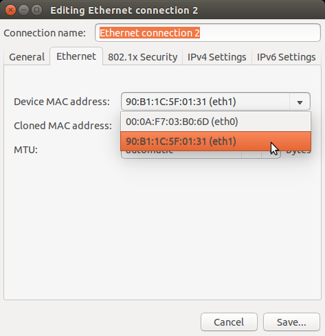
Configure a static IP address for the appropriate interface (Ethernet or USB0). There are many ways to do this in Linux. Network Manager is used here as it is the Ubuntu default and arguably the easiest, especially for ethernet. The next step describes an alternative method to use the more traditional /etc/network/interfaces, which may be easier and more stable for USB. Only one of these methods needs to be used per interface.
Make sure the target board is configured to boot from the appropriate interface (ethernet or USB).
Connect the interface on the PC to the target board. This should create a new connection in Network Manager. Click on Network Manager and choose “edit connections”.
Choose the appropriate connection and edit it to have a static (Ubuntu refers to this as “manual”) IP address. Use the below settings unless there is a good reason not to (and the appropriate changes has been made throughout this guide).
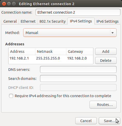
Save all of your changes.
If using USB, there’s one additional step. The USB network interface goes up and down throughout the boot process. The isc-dhcp-server needs to be restarted when it comes up each time. Network Manager provides a capability to do this using the dispatcher.
As root, create /etc/NetworkManager/dispatcher.d/99am-usb-dhcp-server
#!/bin/sh

IF=$1
STATUS=$2

if [ "$IF" = "usb0" ] && [ "$STATUS" = "up" ]; then
     service isc-dhcp-server restart
fi
Make sure this file is executable.
sudo chmod +x /etc/NetworkManager/dispatcher.d/99am-usb-dhcp-server
Restart Network Manager:
sudo service network-manager restart
This step is an alternative to the above step which describes how to use Network Manager to set up a network connection. Depending on the configuration of the software running on your target board, it might be easier to configure the network interface using the more traditional /etc/network/interfaces. or ifconfig. For USB, this method can be easier and more stable, since the USB Network Gadget uses random host MAC addresses by default (it can be configured to use the same address, if desired). Network Manager uses the MAC address to configure a connection. For random booting to a kernel or for flashing or mounting NFS, this is not convenient. The more traditional ifconfig model is configured at an interface level and avoids these issues.
Configure /etc/network/interfaces by adding the below structure for usb0:
allow-hotplug usb0
iface usb0 inet static
address 192.168.2.1
network 192.168.2.0
netmask 255.255.255.0
broadcast 192.168.2.255
up /etc/network/if-up.d/usb-interfaces
Add the below script to /etc/network/if-up.d as sudo with the filename “usb-interfaces” (this is called by the “up” command in /etc/network/interfaces). This script restarts the DHCP/BOOTP server automatically.
#!/bin/sh

if [ "$IFACE" = usb0 ]; then
    sudo service isc-dhcp-server restart
fi
Make sure the script is executable as well.
chmod +x /etc/network/if-up.d/usb-interfaces
Finally, make sure Network Manager is set up to ignore interfaces managed by /etc/network/interfaces by adding the below code to /etc/NetworkManager/NetworkManager.conf:
[main]
plugins=ifupdown

[ifupdown]
managed=false
Restart Network Manager for the changes to take affect.
sudo service network-manager restart
At this point, the Ubuntu box should be set up to host the boot process for an AM335x/AM437x based board. If you already have files to use, copy them to /tftpboot on a Linux box or to Uniflash on a Windows system and reset/power-on the target board with the appropriate connections in place. It is very helpful to have a serial console connection to watch the process proceed. If you have trouble, please see the troubleshooting section below.
6.1.12.2. How to Get Images
The Processor SDK for Linux provides everything needed to create a network bootable set of files (SPL, U-Boot, and Kernel).
Here’s a quick review of the boot process needed.
- Board configured to boot from either Ethernet or USB0. By default, the Beaglebone Black will attempt to boot over USB0.
- U-Boot configured with either Ethernet (this is called CPSW on the AM335x/AM437x family) or USB RNDIS. The RBL will request the file set up in the steps above. This should be an appropriately configured SPL.
- SPL will need to be configured to include the appropriate networking components. It will use this to get U-Boot.
- U-Boot needs to be appropriately configured as well.
The prebuilt images that come with the SDK provide the support necessary to boot over either Ethernet or USB. These images are provided with the SDK in the board-support/prebuilt-images directory within the SDK install. For U-Boot, simply copy the appropriate .bin and and .img files to the /tftpboot directory and rename them to u-boot-spl-restore.bin and u-boot-restore.img, respectively.
6.1.12.3. Troubleshooting
Here are some things to do to debug the setup:
- Since we are dealing with network interfaces, Wireshark is invaluable. Use it to monitor the network connection and determine where things are going wrong:
- If you don’t see BOOTP requests coming from the board, it many not be set up correctly to boot from that interface.
- You can easily see IP Address mismatches if the client is trying to send packets to the wrong place.
- You can monitor the TFTP transfers that are trying to occur. This can reveal filename mismatches, incorrect configurations, etc.
- By default, the DHCP server logs output to /var/log/syslog. This can be very valuable information.
6.1.13. Processor SDK IPC Quick Start Guide
Please refer to IPC Quick Started Guide chapter for details.
6.1.14. Create DSP and IPU firmware using PDK drivers and IPC to load from ARM Linux
Please refer to IPC on AM57xx chapter for details.