3.7. IPC
3.7.1. Overview
Overview
Getting Started
| Links | Description |
|---|---|
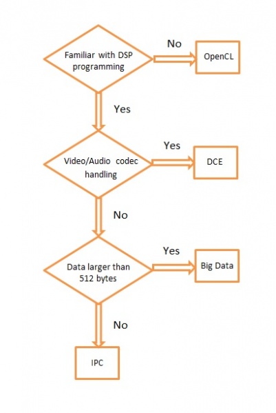
| Multiple Ways of ARM/DSP Communication | Provides brief overview of each method and pros and cons |
| IPC Quick Start Guide | Building and setting up examples for IPC with Processor SDK |
Technical Documents
| Links | Description |
|---|---|
| IPC User’s Guide | TI IPC User’s Guide |
Starting IPC project
| Links | Description |
|---|---|
| Linux IPC on AM57xx | General info on IPC under Linux environment for AM57xx |
| Linux IPC on AM65xx | General info on IPC under Linux environment for AM65xx |
| Linux IPC on K2x | General info on IPC under Linux environment for K2x |
| Running IPC example on DRA7xx/AM572x | Info on running RTOS IPC examples on DRA7xx/AM572x |
| Training video on how to Run IPC example on AM572x | Step-by-step Video on running the IPC examples under Linux environment on AM572x |
| AM57x Customizing Multicore Application | Info and guide to customize memory usage for custom design based on AM57x |
| Modifying Memory Usage For IPUMM using DRA7xx | Info on modifying memory usage of IPU for DRA7xx |
3.7.2. IPC Quick Start Guide
Overview
This wiki page is meant to be a Quick Start Guide for applications using IPC (Inter Processor Communication) in Processor SDK.
It begins with details about the out-of-box demo provided in the Processor SDK Linux filesystem, followed by rebuilding the demo code and running the built images. ( This covers the use case with the Host running linux OS and the slave cores running RTOS).
Also details about building and running the IPC examples are covered.
The goal is to provides information for users to get familiar with IPC and its build environment, in turn, to help users in developing their projects quickly.
Linux out of box demos
The out of box demo is only available on Keystone-2 EVMs.
Note
This assumes the release images are loaded in the flash/SD Card. If needed to update to latest release follow the https://processors.wiki.ti.com/index.php/Processor_SDK_Linux_Getting_Started_Guide to update the release images on flash memory/SD card on the EVM using Program-evm or using the procedures for SD Card.
Connect the EVM Ethernet port 0 to a corporate or local network with DHCP server running, when the Linux kernel boots up, the rootfs start up scripts will get an IP address from the DHCP server and print the IP address to the EVM on-board LCD.
Open an Internet browser (e.g. Mozilla Firefox) on a remote computer that connects with the same network as the EVM.
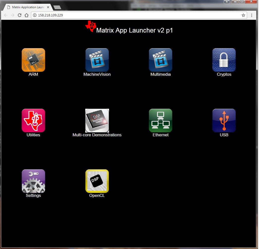
Type the IP address displayed on EVM LCD to the browser and click cancel button to launch the Matrix launcher in the remote access mode instead of on the on-board display device.
Click the Multi-core Demonstrations, then Multi-core IPC Demo to start the IPC demonstration.
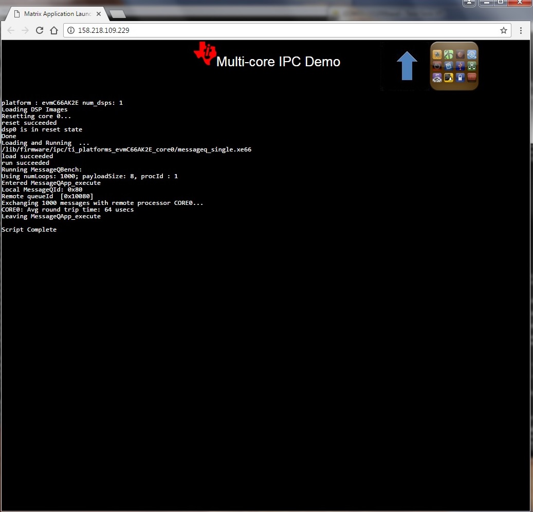
The result from running IPC Demo
Note
To view the out-of-box demo source code, please install Linux and RTOS Processor SDKs from SDK download page
The source code are located in:
Linux side application: <RTOS_SDK_INSTALL_DIR>/ipc_x_xx_xx_xx/linux/src/tests/MessageQBench.c
DSP side application:   <RTOS_SDK_INSTALL_DIR>/ipc_x_xx_xx_xx/packages/ti/ipc/tests/messageq_single.c
Rebuilding the demo:
1. Install Linux Proc SDK at the default location
2. Include cross-compiler directory in the $PATH
export PATH=<sdk path>/linux-devkit/sysroots/x86_64-arago-linux/usr/bin:$PATH
3. Setup TI RTOS PATH using
export TI_RTOS_PATH=<RTOS_SDK_INSTALL_DIR>
export IPC_INSTALL_PATH=<RTOS_SDK_IPC_DIR>
4. In Linux Proc SDK, start the top level build:
$ make ti-ipc-linux
- 5. The ARM binary will be located under the directory where the
- source code is <RTOS_SDK_INSTALL_DIR>/ipc_x_xx_xx_xx/linux/src/tests/
Note
Please follow the build instruction in Linux Kernel User Guide to set up the build environment.
1. Install RTOS Proc SDK at the default location
- 2. If RTOS Proc SDK and tools are not installed at its default
- location, then the environment variables, SDK_INSTALL_PATH and TOOLS_INSTALL_PATH need to be exported with their installed locations.
export SDK_INSTALL_PATH=<RTOS_SDK_INSTALL_DIR>
export TOOLS_INSTALL_PATH=<RTOS_SDK_INSTALL_DIR>
Note
For ProcSDK 3.2 or older releases, tools are not included in RTOS SDK, so point to CCS:
export TOOLS_INSTALL_PATH=<TI_CCS_INSTALL_DIR>
- 3. Configure the build environment in
- <RTOS_SDK_INSTALL_DIR>/processor_sdk_rtos_<platform>_x_xx_xx_xx directory
$ cd <RTOS_SDK_INSTALL_DIR>/processor_sdk_rtos_<platform>_x_xx_xx_xx
$ source ./setupenv.sh
4. Start the top level build:
$ make ipc_bios
- 5. The DSP binary will be located under the directory where the
- source code is
<RTOS_SDK_INSTALL_DIR>/ipc_x_xx_xx_xx/packages/ti/ipc/tests
Build IPC Linux examples
IPC package and its examples are delivered in RTOS Processor SDK, but can be built from Linux Proc SDK. To build IPC examples, both Linux and RTOS processor SDKs need to be installed. They can be downloaded from SDK download page
To install Linux Proc SDK, please follow the instruction in Linux SDK Getting Started Guide
To Install RTOS Proc SDK, please follow the instructions in RTOS SDK Getting Started Guide
Once the Linux and RTOS Processor SDKs are installed at their default locations, the IPC Linux library, not included in the Linux Proc SDK, can be built on Linux host machine with the following commands:
$ cd <TI_LINUX_PROC_SDK_INSTALL_DIR>
$ make ti-ipc-linux
The IPC examples in RTOS Proc SDK including out-of-box demo can be built with the following commands:
$ cd <TI_LINUX_PROC_SDK_INSTALL_DIR>
$ make ti-ipc-linux-examples
Note
Please follow the build instruction in Linux Kernel User Guide to set up the build environment.
Note
If RTOS Proc SDK is not installed at its default location, then the environment variables, TI_RTOS_PATH needs to be exported with their installed locations.
export TI_RTOS_PATH=<TI_RTOS_PROC_SDK_INSTALL_DIR>
Also if using Processor SDK 3.2 or older release, need to also set TI_CCS_PATH to CCSV6 location
export TI_CCS_PATH=<TI_CCS_INSTALL_DIR>/ccsv6
Run IPC Linux examples
- The executables are in RTOS Proc SDK under the ipc_xx_xx_xx_xx/examples directory.
<device>_<OS>_elf/ex<xx_yyyy>/host/bin/debug/app_host
<device>_<OS>_elf/ex<xx_yyyyyy/<processor_or_component>/bin/debug/<ServerCore_or_component.xe66 for DSP
<device>_<OS>_elf/ex<xx_yyyyyy/<processor_or_component>/bin/debug/<sServerCore_or_component.xem4 for IPU
- Copy the executables to the target filesystem. It can also be done by running “make ti-ipc-linux-examples_install” to install the binaries to DESTDIR if using NFS filesystem. ( See Moving_Files_to_the_Target_System for details of moving files to filesystem)
- Load and start the executable on the target DSP/IPU.
For AM57x platforms, Modify the symbolic links in /lib/firmware of the default image names to the built binaries. The images pointed by the symbolic links will be downloaded to and started execution on the corresponding processors by remoteproc during Linux Kernel boots.
DSP image files: dra7-dsp1-fw.xe66  dra7-dsp2-fw.xe66
IPU image files:  dra7-ipu1-fw.xem4  dra7-ipu2-fw.xem4
For OMAP-L138 platform, Modify the symblic link in /lib/firmware of the default image names to the build binary
DSP image files: rproc-dsp-fw
For Keystone-2 platforms, use the Multi-Processor Manager (MPM) Command Line utilities to download and start the DSP executibles. Please refer to /usr/bin/mc_demo_ipc.sh for examples
The available commands are:
   mpmcl reset <dsp core>
   mpmcl status <dsp core>
   mpmcl load <dsp core>
   mpmcl run <dsp core>
- Run the example From the Linux kernel prompt, run the host executable, app_host. An example from running ex02_messageq:
root@am57xx-evm:~# ./app_host DSP1
The console output:
--> main:
--> Main_main:
--> App_create:
App_create: Host is ready
<-- App_create:
--> App_exec:
App_exec: sending message 1
App_exec: sending message 2
App_exec: sending message 3
App_exec: message received, sending message 4
App_exec: message received, sending message 5
App_exec: message received, sending message 6
App_exec: message received, sending message 7
App_exec: message received, sending message 8
App_exec: message received, sending message 9
App_exec: message received, sending message 10
App_exec: message received, sending message 11
App_exec: message received, sending message 12
App_exec: message received, sending message 13
App_exec: message received, sending message 14
App_exec: message received, sending message 15
App_exec  : message received
App_exec: message received
App_exec: message received
<-- App_exec: 0
--> App_delete:
<-- App_delete:
<-- Main_main:
<-- main:
root@am57xx-evm:~#
Build IPC RTOS examples
The IPC package also includes examples for the use case with Host and the slave cores running RTOS/BIOS. They can be built from the Processor SDK RTOS package.
Note
To Install RTOS Proc SDK, please follow the instructions in RTOS SDK Getting Started Guide In the RTOS Processor SDK, the ipc examples are located under <RTOS_SDK_INSTALL_DIR>/processor_sdk_rtos_<platform>_x_xx_xx_xx/ipc_<version>/examples/<platform>_bios_elf.
NOTE: The platform in the directory name may be slightly different from the top level platform name. For example, platform name DRA7XX refer to common examples for DRA7XX & AM57x family of processors.
Once the RTOS Processor SDKs is installed at the default location, the IPC examples can be built with the following commands:
1. Configure the build environment in
   <RTOS_SDK_INSTALL_DIR>/processor_sdk_rtos_<platform>_x_xx_xx_xx directory
     $ cd <RTOS_SDK_INSTALL_DIR>/processor_sdk_rtos_<platform>_x_xx_xx_xx
     $ source ./setupenv.sh
2. Start the top level build:
     $ make ipc_examples
Note
If RTOS Proc SDK and tools are not installed at its default location, then the environment variables, SDK_INSTALL_PATH and TOOLS_INSTALL_PATH need to be exported with their installed locations.
Run IPC RTOS examples
The binary images for the examples are located in the corresponding directories for host and the individual cores. The examples can be run by loading and running the binaries using CCS through JTAG.
Build your own project
After exercising the IPC build and running examples, users can take further look at the source code of the examples as references for their own project.
The sources for examples are under ipc_xx_xx_xx_xx/examples/<device>_<OS>_elf directories. Once modified the same build process described above can be used to rebuild the examples.
3.7.3. IPC for AM57xx
Introduction
This article is geared toward AM57xx users that are running Linux on the Cortex A15. The goal is to help users understand how to gain entitlement to the DSP (c66x) and IPU (Cortex M4) subsystems of the AM57xx.
AM572x device has two IPU subsystems (IPUSS), each of which has 2 cores. IPU2 is used as a controller in multi-media applications, so if you have Processor SDK Linux running, chances are that IPU2 already has firmware loaded. However, IPU1 is open for general purpose programming to offload the ARM tasks.
There are many facets to this task: building, loading, debugging, MMUs, memory sharing, etc. This article intends to take incremental steps toward understanding all of those pieces.
Software Dependencies to Get Started
Prerequisites
- Processor SDK Linux for AM57xx (Version 3.01 or newer needed)
- Processor SDK RTOS for AM57xx
- Code Composer Studio (choose version as specified on Proc SDK download page)
Note
Please be sure that you have the same version number for both Processor SDK RTOS and Linux.
For reference within the context of this wiki page, the Linux SDK is installed at the following location:
/mnt/data/user/ti-processor-sdk-linux-am57xx-evm-xx.xx.xx.xx
├── bin
├── board-support
├── docs
├── example-applications
├── filesystem
├── ipc-build.txt
├── linux-devkit
├── Makefile
├── Rules.make
└── setup.sh
The RTOS SDK is installed at:
/mnt/data/user/my_custom_install_sdk_rtos_am57xx_xx.xx
├── bios_6_xx_xx_xx
├── cg_xml
├── ctoolslib_x_x_x_x
├── dsplib_c66x_x_x_x_x
├── edma3_lld_2_xx_xx_xx
├── framework_components_x_xx_xx_xx
├── imglib_c66x_x_x_x_x
├── ipc_3_xx_xx_xx
├── mathlib_c66x_3_x_x_x
├── ndk_2_xx_xx_xx
├── opencl_rtos_am57xx_01_01_xx_xx
├── openmp_dsp_am57xx_2_04_xx_xx
├── pdk_am57xx_x_x_x
├── processor_sdk_rtos_am57xx_x_xx_xx_xx
├── uia_2_xx_xx_xx
├── xdais_7_xx_xx_xx
CCS is installed at:
/mnt/data/user/ti/my_custom_ccs_x.x.x_install
├── ccsvX
│   ├── ccs_base
│   ├── doc
│   ├── eclipse
│   ├── install_info
│   ├── install_logs
│   ├── install_scripts
│   ├── tools
│   ├── uninstall_ccs
│   ├── uninstall_ccs.dat
│   ├── uninstallers
│   └── utils
├── Code Composer Studio x.x.x.desktop
└── xdctools_x_xx_xx_xx_core
    ├── bin
    ├── config.jar
    ├── docs
    ├── eclipse
    ├── etc
    ├── gmake
    ├── include
    ├── package
    ├── packages
    ├── package.xdc
    ├── tconfini.tcf
    ├── xdc
    ├── xdctools_3_xx_xx_xx_manifest.html
    ├── xdctools_3_xx_xx_xx_release_notes.html
    ├── xs
    └── xs.x86U
Typical Boot Flow on AM572x for ARM Linux users
AM57xx SOC’s have multiple processor cores - Cortex A15, C66x DSP’s and ARM M4 cores. The A15 typically runs a HLOS like Linux/QNX/Android and the remotecores(DSP’s and M4’s) run a RTOS. In the normal operation, boot loader(U-Boot/SPL) boots and loads the A15 with the HLOS. The A15 boots the DSP and the M4 cores.
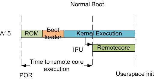
In this sequence, the interval between the Power on Reset and the remotecores (i.e. the DSP’s and the M4’s) executing is dependent on the HLOS initialization time.
Getting Started with IPC Linux Examples
The figure below illustrates how remoteproc/rpmsg driver from ARM Linux kernel communicates with IPC driver on slave processor (e.g. DSP, IPU, etc) running RTOS.
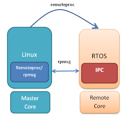
In order to setup IPC on slave cores, we provide some pre-built examples in IPC package that can be run from ARM Linux. The subsequent sections describe how to build and run this examples and use that as a starting point for this effort.
Building the Bundled IPC Examples
The instructions to build IPC examples found under ipc_3_xx_xx_xx/examples/DRA7XX_linux_elf have been provided in the `Processor_SDK IPC Quick Start Guide <https://processors.wiki.ti.com/index.php/Processor_SDK_IPC_Quick_Start_Guide#Build_IPC_Linux_examples>`__.
Let’s focus on one example in particular, ex02_messageq, which is located at <rtos-sdk-install-dir>/ipc_3_xx_xx_xx/examples/DRA7XX_linux_elf/ex02_messageq. Here are the key files that you should see after a successful build:
├── dsp1
│   └── bin
│       ├── debug
│       │   └── server_dsp1.xe66
│       └── release
│           └── server_dsp1.xe66
├── dsp2
│   └── bin
│       ├── debug
│       │   └── server_dsp2.xe66
│       └── release
│           └── server_dsp2.xe66
├── host
│       ├── debug
│       │   └── app_host
│       └── release
│           └── app_host
├── ipu1
│   └── bin
│       ├── debug
│       │   └── server_ipu1.xem4
│       └── release
│           └── server_ipu1.xem4
└── ipu2
    └── bin
        ├── debug
        │   └── server_ipu2.xem4
        └── release
            └── server_ipu2.xem4
Running the Bundled IPC Examples
On the target, let’s create a directory called ipc-starter:
root@am57xx-evm:~# mkdir -p /home/root/ipc-starter
root@am57xx-evm:~# cd /home/root/ipc-starter/
You will need to copy the ex02_messageq directory of your host PC to that directory on the target (through SD card, NFS export, SCP, etc.). You can copy the entire directory, though we’re primarily interested in these files:
- dsp1/bin/debug/server_dsp1.xe66
- dsp2/bin/debug/server_dsp2.xe66
- host/bin/debug/app_host
- ipu1/bin/debug/server_ipu1.xem4
- ipu2/bin/debug/server_ipu2.xem4
The remoteproc driver is hard-coded to look for specific files when loading the DSP/M4. Here are the files it looks for:
- /lib/firmware/dra7-dsp1-fw.xe66
- /lib/firmware/dra7-dsp2-fw.xe66
- /lib/firmware/dra7-ipu1-fw.xem4
- /lib/firmware/dra7-ipu2-fw.xem4
These are generally a soft link to the intended executable. So for example, let’s update the DSP1 executable on the target:
root@am57xx-evm:~# cd /lib/firmware/
root@am57xx-evm:/lib/firmware# rm dra7-dsp1-fw.xe66
root@am57xx-evm:/lib/firmware# ln -s /home/root/ipc-starter/ex02_messageq/dsp1/bin/debug/server_dsp1.xe66 dra7-dsp1-fw.xe66
To reload DSP1 with this new executable, we perform the following steps:
root@am57xx-evm:/lib/firmware# cd /sys/bus/platform/drivers/omap-rproc/
root@am57xx-evm:/sys/bus/platform/drivers/omap-rproc# echo 40800000.dsp > unbind
[27639.985631] omap_hwmod: mmu0_dsp1: _wait_target_disable failed
[27639.991534] omap-iommu 40d01000.mmu: 40d01000.mmu: version 3.0
[27639.997610] omap-iommu 40d02000.mmu: 40d02000.mmu: version 3.0
[27640.017557] omap_hwmod: mmu1_dsp1: _wait_target_disable failed
[27640.030571] omap_hwmod: mmu0_dsp1: _wait_target_disable failed
[27640.036605]  remoteproc2: stopped remote processor 40800000.dsp
[27640.042805]  remoteproc2: releasing 40800000.dsp
root@am57xx-evm:/sys/bus/platform/drivers/omap-rproc# echo 40800000.dsp > bind
[27645.958613] omap-rproc 40800000.dsp: assigned reserved memory node dsp1_cma@99000000
[27645.966452]  remoteproc2: 40800000.dsp is available
[27645.971410]  remoteproc2: Note: remoteproc is still under development and considered experimental.
[27645.980536]  remoteproc2: THE BINARY FORMAT IS NOT YET FINALIZED, and backward compatibility isn't yet guaranteed.
root@am57xx-evm:/sys/bus/platform/drivers/omap-rproc# [27646.008171]  remoteproc2: powering up 40800000.dsp
[27646.013038]  remoteproc2: Booting fw image dra7-dsp1-fw.xe66, size 4706800
[27646.028920] omap_hwmod: mmu0_dsp1: _wait_target_disable failed
[27646.034819] omap-iommu 40d01000.mmu: 40d01000.mmu: version 3.0
[27646.040772] omap-iommu 40d02000.mmu: 40d02000.mmu: version 3.0
[27646.058323]  remoteproc2: remote processor 40800000.dsp is now up
[27646.064772] virtio_rpmsg_bus virtio2: rpmsg host is online
[27646.072271]  remoteproc2: registered virtio2 (type 7)
[27646.078026] virtio_rpmsg_bus virtio2: creating channel rpmsg-proto addr 0x3d
More info related to loading firmware to the various cores can be found here.
Finally, we can run the example on DSP1:
root@am57xx-evm:/sys/bus/platform/drivers/omap-rproc# cd /home/root/ipc-starter/ex02_messageq/host/bin/debug
root@am57xx-evm:~/ipc-starter/ex02_messageq/host/bin/debug# ./app_host DSP1
--> main:
[33590.700700] omap_hwmod: mmu0_dsp2: _wait_target_disable failed
[33590.706609] omap-iommu 41501000.mmu: 41501000.mmu: version 3.0
[33590.718798] omap-iommu 41502000.mmu: 41502000.mmu: version 3.0
--> Main_main:
--> App_create:
App_create: Host is ready
<-- App_create:
--> App_exec:
App_exec: sending message 1
App_exec: sending message 2
App_exec: sending message 3
App_exec: message received, sending message 4
App_exec: message received, sending message 5
App_exec: message received, sending message 6
App_exec: message received, sending message 7
App_exec: message received, sending message 8
App_exec: message received, sending message 9
App_exec: message received, sending message 10
App_exec: message received, sending message 11
App_exec: message received, sending message 12
App_exec: message received, sending message 13
App_exec: message received, sending message 14
App_exec: message received, sending message 15
App_exec: message received
App_exec: message received
App_exec: message received
<-- App_exec: 0
--> App_delete:
<-- App_delete:
<-- Main_main:
<-- main:
Understanding the Memory Map
Overall Linux Memory Map
root@am57xx-evm:~# cat /proc/iomem
[snip...]
58060000-58078fff : core
58820000-5882ffff : l2ram
58882000-588820ff : /ocp/mmu@58882000
80000000-9fffffff : System RAM
  80008000-808d204b : Kernel code
  80926000-809c96bf : Kernel data
a0000000-abffffff : CMEM
ac000000-ffcfffff : System RAM
CMA Carveouts
root@am57xx-evm:~# dmesg | grep -i cma
[    0.000000] Reserved memory: created CMA memory pool at 0x0000000095800000, size 56 MiB
[    0.000000] Reserved memory: initialized node ipu2_cma@95800000, compatible id shared-dma-pool
[    0.000000] Reserved memory: created CMA memory pool at 0x0000000099000000, size 64 MiB
[    0.000000] Reserved memory: initialized node dsp1_cma@99000000, compatible id shared-dma-pool
[    0.000000] Reserved memory: created CMA memory pool at 0x000000009d000000, size 32 MiB
[    0.000000] Reserved memory: initialized node ipu1_cma@9d000000, compatible id shared-dma-pool
[    0.000000] Reserved memory: created CMA memory pool at 0x000000009f000000, size 8 MiB
[    0.000000] Reserved memory: initialized node dsp2_cma@9f000000, compatible id shared-dma-pool
[    0.000000] cma: Reserved 24 MiB at 0x00000000fe400000
[    0.000000] Memory: 1713468K/1897472K available (6535K kernel code, 358K rwdata, 2464K rodata, 332K init, 289K bss, 28356K reserved, 155648K  cma-reserved, 1283072K highmem)
[    5.492945] omap-rproc 58820000.ipu: assigned reserved memory node ipu1_cma@9d000000
[    5.603289] omap-rproc 55020000.ipu: assigned reserved memory node ipu2_cma@95800000
[    5.713411] omap-rproc 40800000.dsp: assigned reserved memory node dsp1_cma@9b000000
[    5.771990] omap-rproc 41000000.dsp: assigned reserved memory node dsp2_cma@9f000000
From the output above, we can derive the location and size of each CMA carveout:
| Memory Section | Physical Address | Size |
|---|---|---|
| IPU2 CMA | 0x95800000 | 56 MB |
| DSP1 CMA | 0x99000000 | 64 MB |
| IPU1 CMA | 0x9d000000 | 32 MB |
| DSP2 CMA | 0x9f000000 | 8 MB |
| Default CMA | 0xfe400000 | 24 MB |
For details on how to adjust the sizes and locations of the DSP/IPU CMA carveouts, please see the corresponding section for changing the DSP or IPU memory map.
To adjust the size of the “Default CMA” section, this is done as part of the Linux config:
linux/arch/arm/configs/tisdk_am57xx-evm_defconfig
#
# Default contiguous memory area size:
#
CONFIG_CMA_SIZE_MBYTES=24
CONFIG_CMA_SIZE_SEL_MBYTES=y
CMEM
To view the allocation at run-time:
root@am57xx-evm:~# cat /proc/cmem

Block 0: Pool 0: 1 bufs size 0xc000000 (0xc000000 requested)

Pool 0 busy bufs:

Pool 0 free bufs:
id 0: phys addr 0xa0000000
This shows that we have defined a CMEM block at physical base address of 0xA0000000 with total size 0xc000000 (192 MB). This block contains a buffer pool consisting of 1 buffer. Each buffer in the pool (only one in this case) is defined to have a size of 0xc000000 (192 MB).
Here is where those sizes/addresses were defined for the AM57xx EVM:
linux/arch/arm/boot/dts/am57xx-evm-cmem.dtsi
/ {
       reserved-memory {
               #address-cells = <2>;
               #size-cells = <2>;
               ranges;

               cmem_block_mem_0: cmem_block_mem@a0000000 {
                       reg = <0x0 0xa0000000 0x0 0x0c000000>;
                       no-map;
                       status = "okay";
               };

               cmem_block_mem_1_ocmc3: cmem_block_mem@40500000 {
                       reg = <0x0 0x40500000 0x0 0x100000>;
                       no-map;
                       status = "okay";
               };
       };

       cmem {
               compatible = "ti,cmem";
               #address-cells = <1>;
               #size-cells = <0>;

               #pool-size-cells = <2>;

               status = "okay";

               cmem_block_0: cmem_block@0 {
                       reg = <0>;
                       memory-region = <&cmem_block_mem_0>;
                       cmem-buf-pools = <1 0x0 0x0c000000>;
               };

               cmem_block_1: cmem_block@1 {
                       reg = <1>;
                       memory-region = <&cmem_block_mem_1_ocmc3>;
               };
       };
};
Changing the DSP Memory Map
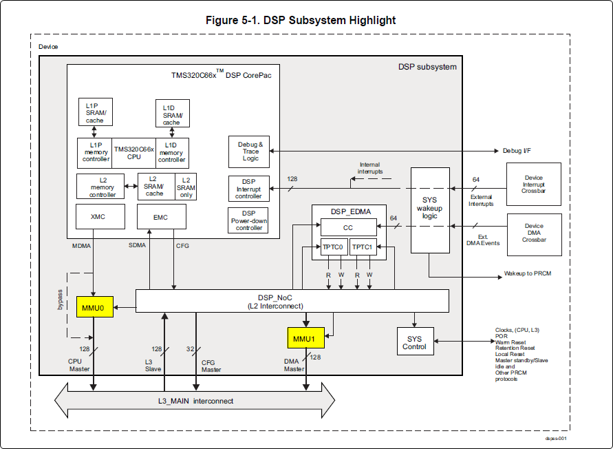
First, it is important to understand that there are a pair of Memory Management Units (MMUs) that sit between the DSP subsystems and the L3 interconnect. One of these MMUs is for the DSP core and the other is for its local EDMA. They both serve the same purpose of translating virtual addresses (i.e. the addresses as viewed by the DSP subsystem) into physical addresses (i.e. addresses as viewed from the L3 interconnect).
DSP Physical Addresses
The physical location where the DSP code/data will actually reside is defined by the CMA carveout. To change this location, you must change the definition of the carveout. The DSP carveouts are defined in the Linux dts file. For example for the AM57xx EVM:
        dsp1_cma_pool: dsp1_cma@99000000 {
                compatible = "shared-dma-pool";
                reg = <0x0 0x99000000 0x0 0x4000000>;
                reusable;
                status = "okay";
        };

        dsp2_cma_pool: dsp2_cma@9f000000 {
                compatible = "shared-dma-pool";
                reg = <0x0 0x9f000000 0x0 0x800000>;
                reusable;
                status = "okay";
        };
};
You are able to change both the size and location. Be careful not to overlap any other carveouts!
Note
The two location entries for a given DSP must be identical!
Additionally, when you change the carveout location, there is a corresponding change that must be made to the resource table. For starters, if you’re making a memory change you will need a custom resource table. The resource table is a large structure that is the “bridge” between physical memory and virtual memory. This structure is utilized for configuring the MMUs that sit in front of the DSP subsystem. There is detailed information available in the article IPC Resource customTable.
Once you’ve created your custom resource table, you must update the address of PHYS_MEM_IPC_VRING to be the same base address as your corresponding CMA.
#if defined (VAYU_DSP_1)
#define PHYS_MEM_IPC_VRING      0x99000000
#elif defined (VAYU_DSP_2)
#define PHYS_MEM_IPC_VRING      0x9F000000
#endif
Note
The PHYS_MEM_IPC_VRING definition from the resource table must match the address of the associated CMA carveout!
DSP Virtual Addresses
These addresses are the ones seen by the DSP subsystem, i.e. these will be the addresses in your linker command files, etc.
You must ensure that the sizes of your sections are consistent with the corresponding definitions in the resource table. You should create your own resource table in order to modify the memory map. This is describe in the wiki page IPC Resource customTable. You can look at an existing resource table inside IPC:
ipc/packages/ti/ipc/remoteproc/rsc_table_vayu_dsp.h
{
    TYPE_CARVEOUT,
    DSP_MEM_TEXT, 0,
    DSP_MEM_TEXT_SIZE, 0, 0, "DSP_MEM_TEXT",
},

{
    TYPE_CARVEOUT,
    DSP_MEM_DATA, 0,
    DSP_MEM_DATA_SIZE, 0, 0, "DSP_MEM_DATA",
},

{
    TYPE_CARVEOUT,
    DSP_MEM_HEAP, 0,
    DSP_MEM_HEAP_SIZE, 0, 0, "DSP_MEM_HEAP",
},

{
    TYPE_CARVEOUT,
    DSP_MEM_IPC_DATA, 0,
    DSP_MEM_IPC_DATA_SIZE, 0, 0, "DSP_MEM_IPC_DATA",
},

{
    TYPE_TRACE, TRACEBUFADDR, 0x8000, 0, "trace:dsp",
},


{
    TYPE_DEVMEM,
    DSP_MEM_IPC_VRING, PHYS_MEM_IPC_VRING,
    DSP_MEM_IPC_VRING_SIZE, 0, 0, "DSP_MEM_IPC_VRING",
},
Let’s have a look at some of these to understand them better. For example:
{
    TYPE_CARVEOUT,
    DSP_MEM_TEXT, 0,
    DSP_MEM_TEXT_SIZE, 0, 0, "DSP_MEM_TEXT",
},
Key points to note are:
- The “TYPE_CARVEOUT” indicates that the physical memory backing this entry will come from the associated CMA pool.
- DSP_MEM_TEXT is a #define earlier in the code providing the address for the code section. It is 0x95000000 by default. This must correspond to a section from your DSP linker command file, i.e. EXT_CODE (or whatever name you choose to give it) must be linked to the same address.
- DSP_MEM_TEXT_SIZE is the size of the MMU pagetable entry being created (1MB in this particular instance). The actual amount of linked code in the corresponding section of your executable must be less than or equal to this size.
Let’s take another:
{
    TYPE_TRACE, TRACEBUFADDR, 0x8000, 0, "trace:dsp",
},
Key points are:
- The “TYPE_TRACE” indicates this is for trace info.
- The TRACEBUFADDR is defined earlier in the file as &ti_trace_SysMin_Module_State_0_outbuf__A. That corresponds to the symbol used in TI-RTOS for the trace buffer.
- The “0x8000” is the size of the MMU mapping. The corresponding size
in the cfg file should be the same (or less). It looks like this:
SysMin.bufSize = 0x8000;
Finally, let’s look at a TYPE_DEVMEM example:
{
    TYPE_DEVMEM,
    DSP_PERIPHERAL_L4CFG, L4_PERIPHERAL_L4CFG,
    SZ_16M, 0, 0, "DSP_PERIPHERAL_L4CFG",
},
Key points:
- The “TYPE_DEVMEM” indicates that we are making an MMU mapping, but this does not come from the CMA pool. This is intended for mapping peripherals, etc. that already exist in the device memory map.
- DSP_PERIPHERAL_L4CFG (0x4A000000) is the virtual address while L4_PERIPHERAL_L4CFG (0x4A000000) is the physical address. This is an identity mapping, meaning that peripherals can be referenced by the DSP using their physical address.
DSP Access to Peripherals
The default resource table creates the following mappings:
| Virtual Address | Physical Address | Size | Comment |
|---|---|---|---|
| 0x4A000000 | 0x4A000000 | 16 MB | L4CFG + L4WKUP |
| 0x48000000 | 0x48000000 | 2 MB | L4PER1 |
| 0x48400000 | 0x48400000 | 4 MB | L4PER2 |
| 0x48800000 | 0x48800000 | 8 MB | L4PER3 |
| 0x54000000 | 0x54000000 | 16 MB | L3_INSTR + CT_TBR |
| 0x4E000000 | 0x4E000000 | 1 MB | DMM config |
In other words, the peripherals can be accessed at their physical addresses since we use an identity mapping.
Inspecting the DSP IOMMU Page Tables at Run-Time
You can dump the DSP IOMMU page tables with the following commands:
| DSP | MMU | Command |
|---|---|---|
| DSP1 | MMU0 | cat /sys/kernel/debug/omap_iommu/40d01000.mmu/pagetable |
| DSP1 | MMU1 | cat /sys/kernel/debug/omap_iommu/40d02000.mmu/pagetable |
| DSP2 | MMU0 | cat /sys/kernel/debug/omap_iommu/41501000.mmu/pagetable |
| DSP2 | MMU1 | cat /sys/kernel/debug/omap_iommu/41502000.mmu/pagetable |
In general, MMU0 and MMU1 are being programmed identically so you really only need to take a look at one or the other to understand the mapping for a given DSP.
For example:
root@am57xx-evm:~# cat /sys/kernel/debug/omap_iommu/40d01000.mmu/pagetable
L:      da:     pte:
--------------------------
1: 0x48000000 0x48000002
1: 0x48100000 0x48100002
1: 0x48400000 0x48400002
1: 0x48500000 0x48500002
1: 0x48600000 0x48600002
1: 0x48700000 0x48700002
1: 0x48800000 0x48800002
1: 0x48900000 0x48900002
1: 0x48a00000 0x48a00002
1: 0x48b00000 0x48b00002
1: 0x48c00000 0x48c00002
1: 0x48d00000 0x48d00002
1: 0x48e00000 0x48e00002
1: 0x48f00000 0x48f00002
1: 0x4a000000 0x4a040002
1: 0x4a100000 0x4a040002
1: 0x4a200000 0x4a040002
1: 0x4a300000 0x4a040002
1: 0x4a400000 0x4a040002
1: 0x4a500000 0x4a040002
1: 0x4a600000 0x4a040002
1: 0x4a700000 0x4a040002
1: 0x4a800000 0x4a040002
1: 0x4a900000 0x4a040002
1: 0x4aa00000 0x4a040002
1: 0x4ab00000 0x4a040002
1: 0x4ac00000 0x4a040002
1: 0x4ad00000 0x4a040002
1: 0x4ae00000 0x4a040002
1: 0x4af00000 0x4a040002
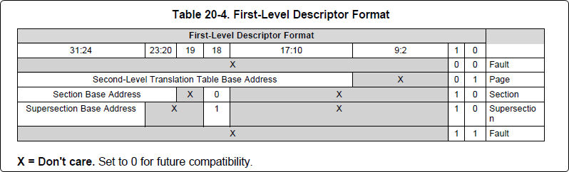
The first column tells us whether the mapping is a Level 1 or Level 2 descriptor. All the lines above are a first level descriptor, so we look at the associated format from the TRM:
The “da” (“device address”) column reflects the virtual address. It is derived from the index into the table, i.e. there does not exist a “da” register or field in the page table. Each MB of the address space maps to an entry in the table. The “da” column is displayed to make it easy to find the virtual address of interest.
The “pte” (“page table entry”) column can be decoded according to Table 20-4 shown above. For example:
1: 0x4a000000 0x4a040002
The 0x4a040002 shows us that it is a Supersection with base address 0x4A000000. This gives us a 16 MB memory page. Note the repeated entries afterward. That’s a requirement of the MMU. Here’s an excerpt from the TRM:
Note
Supersection descriptors must be repeated 16 times, because each descriptor in the first level translation table describes 1 MiB of memory. If an access points to a descriptor that is not initialized, the MMU will behave in an unpredictable way.
Changing Cortex M4 IPU Memory Map
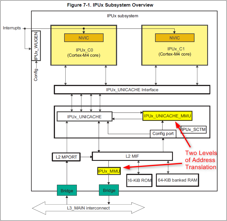
In order to fully understand the memory mapping of the Cortex M4 IPU Subsystems, it’s helpful to recognize that there are two distinct/independent levels of memory translation. Here’s a snippet from the TRM to illustrate:
Cortex M4 IPU Physical Addresses
The physical location where the M4 code/data will actually reside is defined by the CMA carveout. To change this location, you must change the definition of the carveout. The M4 carveouts are defined in the Linux dts file. For example for the AM57xx EVM:
        ipu2_cma_pool: ipu2_cma@95800000 {
                compatible = "shared-dma-pool";
                reg = <0x0 95800000 0x0 0x3800000>;
                reusable;
                status = "okay";
        };

        ipu1_cma_pool: ipu1_cma@9d000000 {
                compatible = "shared-dma-pool";
                reg = <0x0 9d000000 0x0 0x2000000>;
                reusable;
                status = "okay";
        };
};
Note
The two location entries for a given carveout must be identical!
Once you’ve created your custom resource table, you must update the address of PHYS_MEM_IPC_VRING to be the same base address as your corresponding CMA.
#if defined(VAYU_IPU_1)
#define PHYS_MEM_IPC_VRING      0x9D000000
#elif defined (VAYU_IPU_2)
#define PHYS_MEM_IPC_VRING      0x95800000
#endif
Note
The PHYS_MEM_IPC_VRING definition from the resource table must match the address of the associated CMA carveout!
Cortex M4 IPU Virtual Addresses
Unicache MMU
The Unicache MMU sits closest to the Cortex M4. It provides the first level of address translation. The Unicache MMU is actually “self programmed” by the Cortex M4. The Unicache MMU is also referred to as the Attribute MMU (AMMU). There are a fixed number of small, medium and large pages. Here’s a snippet showing some of the key mappings:
ipc_3_43_02_04/examples/DRA7XX_linux_elf/ex02_messageq/ipu1/IpuAmmu.cfg
/*********************** Large Pages *************************/
/* Instruction Code: Large page  (512M); cacheable */
/* config large page[0] to map 512MB VA 0x0 to L3 0x0 */
AMMU.largePages[0].pageEnabled = AMMU.Enable_YES;
AMMU.largePages[0].logicalAddress = 0x0;
AMMU.largePages[0].translationEnabled = AMMU.Enable_NO;
AMMU.largePages[0].size = AMMU.Large_512M;
AMMU.largePages[0].L1_cacheable = AMMU.CachePolicy_CACHEABLE;
AMMU.largePages[0].L1_posted = AMMU.PostedPolicy_POSTED;

/* Peripheral regions: Large Page (512M); non-cacheable */
/* config large page[1] to map 512MB VA 0x60000000 to L3 0x60000000 */
AMMU.largePages[1].pageEnabled = AMMU.Enable_YES;
AMMU.largePages[1].logicalAddress = 0x60000000;
AMMU.largePages[1].translationEnabled = AMMU.Enable_NO;
AMMU.largePages[1].size = AMMU.Large_512M;
AMMU.largePages[1].L1_cacheable = AMMU.CachePolicy_NON_CACHEABLE;
AMMU.largePages[1].L1_posted = AMMU.PostedPolicy_POSTED;

/* Private, Shared and IPC Data regions: Large page (512M); cacheable */
/* config large page[2] to map 512MB VA 0x80000000 to L3 0x80000000 */
AMMU.largePages[2].pageEnabled = AMMU.Enable_YES;
AMMU.largePages[2].logicalAddress = 0x80000000;
AMMU.largePages[2].translationEnabled = AMMU.Enable_NO;
AMMU.largePages[2].size = AMMU.Large_512M;
AMMU.largePages[2].L1_cacheable = AMMU.CachePolicy_CACHEABLE;
AMMU.largePages[2].L1_posted = AMMU.PostedPolicy_POSTED;
| Page | Cortex M4 Address | Intermediate Address | Size | Comment |
|---|---|---|---|---|
| Large Page 0 | 0x00000000-0x1fffffff | 0x00000000-0x1fffffff | 512 MB | Code |
| Large Page 1 | 0x60000000-0x7fffffff | 0x60000000-0x7fffffff | 512 MB | Peripherals |
| Large Page 2 | 0x80000000-0x9fffffff | 0x80000000-0x9fffffff | 512 MB | Data |
These 3 pages are “identity” mappings, performing a passthrough of requests to the associated address ranges. These intermediate addresses get mapped to their physical addresses in the next level of translation (IOMMU).
The AMMU ranges for code and data need to be identity mappings because otherwise the remoteproc loader wouldn’t be able to match up the sections from the ELF file with the associated IOMMU mapping. These mappings should suffice for any application, i.e. no need to adjust these. The more likely area for modification is the resource table in the next section. The AMMU mappings are needed mainly to understand the full picture with respect to the Cortex M4 memory map.
IOMMU
The IOMMU sits closest to the L3 interconnect. It takes the intermediate address output from the AMMU and translates it to the physical address used by the L3 interconnect. The IOMMU is programmed by the ARM based on the associated resource table. If you’re planning any memory changes then you’ll want to make a custom resource table as described in the wiki page IPC Resource customTable.
The default resource table (which can be adapted to make a custom table) can be found at this location:
ipc/packages/ti/ipc/remoteproc/rsc_table_vayu_ipu.h
#define IPU_MEM_TEXT            0x0
#define IPU_MEM_DATA            0x80000000

#define IPU_MEM_IOBUFS          0x90000000

#define IPU_MEM_IPC_DATA        0x9F000000
#define IPU_MEM_IPC_VRING       0x60000000
#define IPU_MEM_RPMSG_VRING0    0x60000000
#define IPU_MEM_RPMSG_VRING1    0x60004000
#define IPU_MEM_VRING_BUFS0     0x60040000
#define IPU_MEM_VRING_BUFS1     0x60080000

#define IPU_MEM_IPC_VRING_SIZE  SZ_1M
#define IPU_MEM_IPC_DATA_SIZE   SZ_1M

#if defined(VAYU_IPU_1)
#define IPU_MEM_TEXT_SIZE       (SZ_1M)
#elif defined(VAYU_IPU_2)
#define IPU_MEM_TEXT_SIZE       (SZ_1M * 6)
#endif

#if defined(VAYU_IPU_1)
#define IPU_MEM_DATA_SIZE       (SZ_1M * 5)
#elif defined(VAYU_IPU_2)
#define IPU_MEM_DATA_SIZE       (SZ_1M * 48)
#endif
<snip...>
{
    TYPE_CARVEOUT,
    IPU_MEM_TEXT, 0,
    IPU_MEM_TEXT_SIZE, 0, 0, "IPU_MEM_TEXT",
},

{
    TYPE_CARVEOUT,
    IPU_MEM_DATA, 0,
    IPU_MEM_DATA_SIZE, 0, 0, "IPU_MEM_DATA",
},

{
    TYPE_CARVEOUT,
    IPU_MEM_IPC_DATA, 0,
    IPU_MEM_IPC_DATA_SIZE, 0, 0, "IPU_MEM_IPC_DATA",
},
The 3 entries above from the resource table all come from the associated IPU CMA pool (i.e. as dictated by the TYPE_CARVEOUT). The second parameter represents the virtual address (i.e. input address to the IOMMU). These addresses must be consistent with both the AMMU mapping as well as the linker command file. The ex02_messageq example from ipc defines these memory sections in the file examples/DRA7XX_linux_elf/ex02_messageq/shared/config.bld.
You can dump the IPU IOMMU page tables with the following commands:
| IPU | Command |
|---|---|
| IPU1 | cat /sys/kernel/debug/omap_iommu/58882000.mmu/pagetable |
| IPU2 | cat /sys/kernel/debug/omap_iommu/55082000.mmu/pagetable |
Please see the corresponding DSP documentation for more details on interpreting the output.
Cortex M4 IPU Access to Peripherals
The default resource table creates the following mappings:
| Virtual Address used by Cortex M4 | Address at output of Unicache MMU | Address at output of IOMMU | Size | Comment |
|---|---|---|---|---|
| 0x6A000000 | 0x6A000000 | 0x4A000000 | 16 MB | L4CFG + L4WKUP |
| 0x68000000 | 0x68000000 | 0x48000000 | 2 MB | L4PER1 |
| 0x68400000 | 0x68400000 | 0x48400000 | 4 MB | L4PER2 |
| 0x68800000 | 0x68800000 | 0x48800000 | 8 MB | L4PER3 |
| 0x74000000 | 0x74000000 | 0x54000000 | 16 MB | L3_INSTR + CT_TBR |
Example: Accessing UART5 from IPU
- For this example, it’s assumed the pin-muxing was already setup in the bootloader. If that’s not the case, you would need to do that here.
- The UART5 module needs to be enabled via the CM_L4PER_UART5_CLKCTRL register. This is located at physical address 0x4A009870. So from the M4 we would program this register at virtual address 0x6A009870. Writing a value of 2 to this register will enable the peripheral.
- After completing the previous step, the UART5 registers will become accessible. Normally UART5 is accessible at physical base address 0x48066000. This would correspondingly be accessed from the IPU at 0x68066000.
Power Management
The IPUs and DSPs auto-idle by default. This can prevent you from being able to connect to the device using JTAG or from accessing local memory via devmem2. There are some options sprinkled throughout sysfs that are needed in order to force these subsystems on, as is sometimes needed for development and debug purposes.
There are some hard-coded device names that originate in the device tree (dra7.dtsi) that are needed for these operations:
| Remote Core | Definition in dra7.dtsi | System FS Name |
|---|---|---|
| IPU1 | ipu@58820000 | 58820000.ipu |
| IPU2 | ipu@55020000 | 55020000.ipu |
| DSP1 | dsp@40800000 | 40800000.dsp |
| DSP2 | dsp@41000000 | 41000000.dsp |
| ICSS1-PRU0 | pru@4b234000 | 4b234000.pru0 |
| ICSS1-PRU1 | pru@4b238000 | 4b238000.pru1 |
| ICSS2-PRU0 | pru@4b2b4000 | 4b2b4000.pru0 |
| ICSS2-PRU1 | pru@4b2b8000 | 4b2b8000.pru1 |
To map these System FS names to the associated remoteproc entry, you can run the following commands:
root@am57xx-evm:~# ls -l /sys/kernel/debug/remoteproc/
root@am57xx-evm:~# cat /sys/kernel/debug/remoteproc/remoteproc*/name
The results of the commands will be a one-to-one mapping. For example, 58820000.ipu corresponds with remoteproc0.
Similarly, to see the power state of each of the cores:
root@am57xx-evm:~# cat /sys/class/remoteproc/remoteproc*/state
The state can be suspended, running, offline, etc. You can only attach JTAG if the state is “running”. If it shows as “suspended” then you must force it to run. For example, let’s say DSP0 is “suspended”. You can run the following command to force it on:
root@am57xx-evm:~# echo on > /sys/bus/platform/devices/40800000.dsp/power/control
The same is true for any of the cores, but replace 40800000.dsp with the associated System FS name from the chart above.
Adding IPC to an Existing TI-RTOS Application on slave cores
Adding IPC to an existing TI RTOS application on the DSP
A common thing people want to do is take an existing DSP application and add IPC to it. This is common when migrating from a DSP only solution to a heterogeneous SoC with an Arm plus a DSP. This is the focus of this section.
In order to describe this process, we need an example test case to work with. For this purpose, we’ll be using the GPIO_LedBlink_evmAM572x_c66xExampleProject example that’s part of the PDK (installed as part of the Processor SDK RTOS). You can find it at c:\ti\pdk_am57xx_1_0_4\packages\MyExampleProjects\GPIO_LedBlink_evmAM572x_c66xExampleProject. This example uses SYS/BIOS and blinks the USER0 LED on the AM572x GP EVM, it’s labeled D4 on the EVM silkscreen just to the right of the blue reset button.
There were several steps taken to make this whole process work, each of which will be described in following sections
- Build and run the out-of-box LED blink example on the EVM using Code Composer Studio (CCS)
- Take the ex02_message example from the IPC software bundle and turn it into a CCS project. Build it and modify the Linux startup code to use this new image. This is just a sanity check step to make sure we can build the IPC examples in CCS and have them run at boot up on the EVM.
- In CCS, make a clone of the out-of-box LED example and rename it to denote it’s the IPC version of the example. Then using the ex02_messageq example as a reference, add in the IPC pieces to the LED example. Build from CCS then add it to the Linux firmware folder.
Running LED Blink PDK Example from CCS
TODO - Fill this section in with instructions on how to run the LED blink example using JTAG and CCS after the board has booted Linux.
Note
Some edits were made to the LED blink example to allow it to run in a Linux environment, specifically, removed the GPIO interrupts and then added a Clock object to call the LED GPIO toggle function on a periodic bases.
Make CCS project out of ex02_messageq IPC example
TODO - fill this section in with instructions on how to make a CCS project out of the IPC example source files.
Add IPC to the LED Blink Example
The first step is to clone our out-of-box LED blink CCS project and rename it to denote it’s using IPC. The easiest way to do this is using CCS. Here are the steps...
- In the Edit perspective, go into your Project Explorer window and right click on your GPIO_LedBlink_evmAM572x+c66xExampleProject project and select copy from the pop-up menu. Maske sure the project is not is a closed state.
- Rick click in and empty area of the project explorer window and select past.
- A dialog box pops up, modify the name to denote it’s using IPC. A good name is GPIO_LedBlink_evmAM572x+c66xExampleProjec_with_ipc.
This is the project we’ll be working with from here on. The next thing we want to do is select the proper RTSC platform and other components. To do this, follow these steps.
- Right click on the GPIO_LedBlink_evmAM572x+c66xExampleProjec_with_ipc project and select Properties
- In the left hand pane, click on CCS General.
- On the right hand side, click on the RTSC tab
- For XDCtools version: select 3.32.0.06_core
- In the list of Products and Repositories, check the following...
- IPC 3.43.2.04
- SYS/BIOS 6.45.1.29
- am57xx PDK 1.0.4
- For Target, select ti.targets.elf.C66
- For Platform, select ti.platforms.evmDRA7XX
- Once the platform is selected, edit its name buy hand and append :dsp1 to the end. After this it should be ti.platforms.evmDRA7XX:dsp1
- Go ahead and leave the Build-profile set to debug.
- Hit the OK button.
Now we want to copy configuration and source files from the ex02_messageq IPC example into our project. The IPC example is located at C:\ti\ipc_3_43_02_04\examples\DRA7XX_linux_elf\ex02_messageq. To copy files into your CCS project, you can simply select the files you want in Windows explorer then drag and drop them into your project in CCS.
Copy these files into your CCS project...
- C:\ti\ipc_3_43_02_04\examples\DRA7XX_linux_elf\ex02_messageq\shared\AppCommon.h
- C:\ti\ipc_3_43_02_04\examples\DRA7XX_linux_elf\ex02_messageq\shared\config.bld
- C:\ti\ipc_3_43_02_04\examples\DRA7XX_linux_elf\ex02_messageq\shared\ipc.cfg.xs
Now copy these files into your CCS project...
- C:\ti\ipc_3_43_02_04\examples\DRA7XX_linux_elf\ex02_messageq\dsp1\Dsp1.cfg
- C:\ti\ipc_3_43_02_04\examples\DRA7XX_linux_elf\ex02_messageq\dsp1\MainDsp1.c
- C:\ti\ipc_3_43_02_04\examples\DRA7XX_linux_elf\ex02_messageq\dsp1\Server.c
- C:\ti\ipc_3_43_02_04\examples\DRA7XX_linux_elf\ex02_messageq\dsp1\Server.h
Note
When you copy Dsp1.cfg into your CCS project, it should show up greyed out. This is because the LED blink example already has a cfg file (gpio_test_evmAM572x.cfg). The Dsp1.cfg will be used for copying and pasting. When it’s all done, you can delete it from your project.
Finally, you will likely want to use a custom resource table so copy these files into your CCS project...
- C:\ti\ipc_3_43_02_04\packages\ti\ipc\remoteproc\rsc_table_vayu_dsp.h
- C:\ti\ipc_3_43_02_04\packages\ti\ipc\remoteproc\rsc_types.h
The rsc_table_vayu_dsp.h file defines an initialized structure so let’s make a .c source file.
- In your CCS project, rename rsc_table_vayu_dsp.h to rsc_table_vayu_dsp.c
Now we want to merge the IPC example configuration file with the LED blink example configuration file. Follow these steps...
- Open up Dsp1.cfg using a text editor (don’t open it using the GUI). Right click on it and select Open With -> XDCscript Editor
- We want to copy the entire contents into the clipboard. Select all and copy.
- Now just like above, open the gpio_test_evmAM572x.cfg config file in the text editor. Go to the very bottom and paste in the contents from the Dsp1.cfg file. Basically we’ve appended the contents of Dsp1.cfg into gpio_test_evmAM572x.cfg.
We’ve now added in all the necessary configuration and source files into our project. Don’t expect it to build at this point, we have to make edits first. These edits are listed below.
NOTE, you can download the full CCS project with source files to use as a reference.
See link towards the end of this section.
- Edit gpio_test_evmAM572x.cfg
Add the following to the beginning of your configuration file
var Program = xdc.useModule('xdc.cfg.Program');
Comment out the Memory sections configuration as shown below
/* ================ Memory sections configuration ================ */
//Program.sectMap[".text"] = "EXT_RAM";
//Program.sectMap[".const"] = "EXT_RAM";
//Program.sectMap[".plt"] = "EXT_RAM";
/* Program.sectMap["BOARD_IO_DELAY_DATA"] = "OCMC_RAM1"; */
/* Program.sectMap["BOARD_IO_DELAY_CODE"] = "OCMC_RAM1"; */
Since we are no longer using a shared folder, make the following change
//var ipc_cfg = xdc.loadCapsule("../shared/ipc.cfg.xs");
var ipc_cfg = xdc.loadCapsule("../ipc.cfg.xs");
Comment out the following. We’ll be calling this function directly from main.
//BIOS.addUserStartupFunction('&IpcMgr_ipcStartup');
Increase the system stack size
//Program.stack = 0x1000;
Program.stack = 0x8000;
Comment out the entire TICK section
/* --------------------------- TICK --------------------------------------*/
// var Clock = xdc.useModule('ti.sysbios.knl.Clock');
// Clock.tickSource = Clock.TickSource_NULL;
// //Clock.tickSource = Clock.TickSource_USER;
// /* Configure BIOS clock source as GPTimer5 */
// //Clock.timerId = 0;
//
// var Timer = xdc.useModule('ti.sysbios.timers.dmtimer.Timer');
//
// /* Skip the Timer frequency verification check. Need to remove this later */
// Timer.checkFrequency = false;
//
// /* Match this to the SYS_CLK frequency sourcing the dmTimers.
//  * Not needed once the SYS/BIOS family settings is updated. */
// Timer.intFreq.hi = 0;
// Timer.intFreq.lo = 19200000;
//
// //var timerParams = new Timer.Params();
// //timerParams.period = Clock.tickPeriod;
// //timerParams.periodType = Timer.PeriodType_MICROSECS;
// /* Switch off Software Reset to make the below settings effective */
// //timerParams.tiocpCfg.softreset = 0x0;
// /* Smart-idle wake-up-capable mode */
// //timerParams.tiocpCfg.idlemode = 0x3;
// /* Wake-up generation for Overflow */
// //timerParams.twer.ovf_wup_ena = 0x1;
// //Timer.create(Clock.timerId, Clock.doTick, timerParams);
//
// var Idle = xdc.useModule('ti.sysbios.knl.Idle');
// var Deh = xdc.useModule('ti.deh.Deh');
//
// /* Must be placed before pwr mgmt */
// Idle.addFunc('&ti_deh_Deh_idleBegin');
Make configuration change to use custom resource table. Add to the end of the file.
/* Override the default resource table with my own */
var Resource = xdc.useModule('ti.ipc.remoteproc.Resource');
Resource.customTable = true;
- Edit main_led_blink.c
Add the following external declarations
extern Int ipc_main();
extern Void IpcMgr_ipcStartup(Void);
In main(), add a call to ipc_main() and IpcMgr_ipcStartup() just before BIOS_start()
ipc_main();

if (callIpcStartup) {
    IpcMgr_ipcStartup();
}

/* Start BIOS */
BIOS_start();
return (0);
Comment out the line that calls Board_init(boardCfg). This call is in the original example because it assumes TI-RTOS is running on the Arm but in our case here, we are running Linux and this call is destructive so we comment it out.
#if defined(EVM_K2E) || defined(EVM_C6678)
    boardCfg = BOARD_INIT_MODULE_CLOCK |
    BOARD_INIT_UART_STDIO;
#else
    boardCfg = BOARD_INIT_PINMUX_CONFIG |
    BOARD_INIT_MODULE_CLOCK |
    BOARD_INIT_UART_STDIO;
#endif
    //Board_init(boardCfg);
- Edit MainDsp1.c
The app now has it’s own main(), so rename this one and get rid of args
//Int main(Int argc, Char* argv[])
Int ipc_main()
{
No longer using args so comment these lines
//taskParams.arg0 = (UArg)argc;
//taskParams.arg1 = (UArg)argv;
BIOS_start() is done in the app main() so comment it out here
/* start scheduler, this never returns */
//BIOS_start();
Comment this out
//Log_print0(Diags_EXIT, "<-- main:");
- Edit rsc_table_vayu_dsp.c
Set this #define before it’s used to select PHYS_MEM_IPC_VRING value
#define VAYU_DSP_1
Add this extern declaration prior to the symbol being used
extern char ti_trace_SysMin_Module_State_0_outbuf__A;
- Edit Server.c
No longer have shared folder so change include path
/* local header files */
//#include "../shared/AppCommon.h"
#include "../AppCommon.h"
Download the Full CCS Project
GPIO_LedBlink_evmAM572x_c66xExampleProject_with_ipc.zip
Adding IPC to an existing TI RTOS application on the IPU
A common thing people want to do is take an existing IPU application that may be controlling serial or control interfaces and add IPC to it so that the firmware can be loaded from the ARM. This is common when migrating from a IPU only solution to a heterogeneous SoC with an MPUSS (ARM) and IPUSS. This is the focus of this section.
In order to describe this process, we need an example TI RTOS test case to work with. For this purpose, we’ll be using the UART_BasicExample_evmAM572x_m4ExampleProject example that’s part of the PDK (installed as part of the Processor SDK RTOS). This example uses TI RTOS and does serial IO using UART3 port on the AM572x GP EVM, it’s labeled Serial Debug on the EVM silkscreen.
There were several steps taken to make this whole process work, each of which will be described in following sections
- Build and run the out-of-box UART M4 example on the EVM using Code Composer Studio (CCS)
- Build and run the ex02_messageQ example from the IPC software bundle and turn it into a CCS project. Build it and modify the Linux startup code to use this new image. This is just a sanity check step to make sure we can build the IPC examples in CCS and have them run at boot up on the EVM.
- In CCS, make a clone of the out-of-box UART M4 example and rename it to denote it’s the IPC version of the example. Then using the ex02_messageq example as a reference, add in the IPC pieces to the UART example code. Build from CCS then add it to the Linux firmware folder.
Running UART Read/Write PDK Example from CCS
Developers are required to run pdkProjectCreate script to generate this example as described in the Processor SDK RTOS wiki article.
For the UART M4 example run the script with the following arguments:
pdkProjectCreate.bat AM572x evmAM572x little uart m4
After you run the script, you can find the UART M4 example project at <SDK_INSTALL_PATH>\pdk_am57xx_1_0_4\packages\MyExampleProjects\UART_BasicExample_evmAM572x_m4ExampleProject.
Import the project in CCS and build the example. You can now connect to the EVM using an emulator and CCS using the instructions provided here: https://processors.wiki.ti.com/index.php/AM572x_GP_EVM_Hardware_Setup
Connect to the ARM core and make sure GEL runs multicore initialization and brings the IPUSS out of reset. Connect to IPU2 core0 and load and run the M4 UART example. When you run the code you should see the following log on the serial IO console:
uart driver and utils example test cases :
Enter 16 characters or press Esc
1234567890123456  <- user input
Data received is
1234567890123456  <- loopback from user input
uart driver and utils example test cases :
Enter 16 characters or press Esc
Build and Run ex02_messageq IPC example
Follow instructions described in Article Run IPC Linux Examples
Update Linux Kernel device tree to remove UART that will be controlled by M4
Linux kernel enables all SOC HW modules which are required for its configuration. Appropriate drivers configure required clocks and initialize HW registers. For all unused IPs clocks are not configured.
The uart3 node is disabled in kernel using device tree. Also this restricts kernel to put those IPs to sleep mode.
&uart3 {
    status = "disabled";
    ti,no-idle;
};
Add IPC to the UART Example
The first step is to clone our out-of-box UART example CCS project and rename it to denote it’s using IPC. The easiest way to do this is using CCS. Here are the steps...
- In the Edit perspective, go into your Project Explorer window and right click on your UART_BasicExample_evmAM572x_m4ExampleProject project and select copy from the pop-up menu. Maske sure the project is not is a closed state.
- Rick click in and empty area of the project explorer window and select past.
- A dialog box pops up, modify the name to denote it’s using IPC. A good name is UART_BasicExample_evmAM572x_m4ExampleProject_with_ipc.
This is the project we’ll be working with from here on. The next thing we want to do is select the proper RTSC platform and other components. To do this, follow these steps.
- Right click on the UART_BasicExample_evmAM572x_m4ExampleProject_with_ipc project and select Properties
- In the left hand pane, click on CCS General.
- On the right hand side, click on the RTSC tab
- For XDCtools version: select 3.xx.x.xx_core
- In the list of Products and Repositories, check the following...
- IPC 3.xx.x.xx
- SYS/BIOS 6.4x.x.xx
- am57xx PDK x.x.x
- For Target, select ti.targets.arm.elf.M4
- For Platform, select ti.platforms.evmDRA7XX
- Once the platform is selected, edit its name buy hand and append :ipu2 to the end. After this it should be ti.platforms.evmDRA7XX:ipu2
- Go ahead and leave the Build-profile set to debug.
- Hit the OK button.
Now we want to copy configuration and source files from the ex02_messageq IPC example into our project. The IPC example is located at C:\ti\ipc_3_xx_xx_xx\examples\DRA7XX_linux_elf\ex02_messageq. To copy files into your CCS project, you can simply select the files you want in Windows explorer then drag and drop them into your project in CCS.
Copy these files into your CCS project...
- C:\ti\ipc_3_xx_xx_xx\examples\DRA7XX_linux_elf\ex02_messageq\shared\AppCommon.h
- C:\ti\ipc_3_xx_xx_xx\examples\DRA7XX_linux_elf\ex02_messageq\shared\config.bld
- C:\ti\ipc_3_xx_xx_xx\examples\DRA7XX_linux_elf\ex02_messageq\shared\ipc.cfg.xs
Now copy these files into your CCS project...
- C:\ti\ipc_3_xx_xx_xx\examples\DRA7XX_linux_elf\ex02_messageq\ipu2\Ipu2.cfg
- C:\ti\ipc_3_xx_xx_xx\examples\DRA7XX_linux_elf\ex02_messageq\ipu2\MainIpu2.c
- C:\ti\ipc_3_xx_xx_xx\examples\DRA7XX_linux_elf\ex02_messageq\ipu2\Server.c
- C:\ti\ipc_3_xx_xx_xx\examples\DRA7XX_linux_elf\ex02_messageq\ipu2\Server.h
Note
When you copy Ipu2.cfg into your CCS project, it should show up greyed out. If not, right click and exclude it from build. This is because the UART example already has a cfg file (uart_m4_evmAM572x.cfg). The Ipu2.cfg will be used for copying and pasting. When it’s all done, you can delete it from your project.
Finally, you will likely want to use a custom resource table so copy these files into your CCS project...
- C:\ti\ipc_3_xx_xx_xx\packages\ti\ipc\remoteproc\rsc_table_vayu_ipu.h
- C:\ti\ipc_3_xx_xx_xx\packages\ti\ipc\remoteproc\rsc_types.h
The rsc_table_vayu_dsp.h file defines an initialized structure so let’s make a .c source file.
- In your CCS project, rename rsc_table_vayu_ipu.h to rsc_table_vayu_ipu.c
Now we want to merge the IPC example configuration file with the LED blink example configuration file. Follow these steps...
- Open up Ipu2.cfg using a text editor (don’t open it using the GUI). Right click on it and select Open With -> XDCscript Editor
- We want to copy the entire contents into the clipboard. Select all and copy.
- Now just like above, open the uart_m4_evmAM572x.cfg config file in the text editor. Go to the very bottom and paste in the contents from the Ipu2.cfg file. Basically we’ve appended the contents of Ipu2.cfg into uart_m4_evmAM572x.cfg.
We’ve now added in all the necessary configuration and source files into our project. Don’t expect it to build at this point, we have to make edits first. These edits are listed below.
NOTE, you can download the full CCS project with source files to use as a reference.
See link towards the end of this section.
- Edit uart_m4_evmAM572x.cfg
Add the following to the beginning(at the top) of your configuration file
var Program = xdc.useModule('xdc.cfg.Program');
Since we are no longer using a shared folder, make the following change
//var ipc_cfg = xdc.loadCapsule("../shared/ipc.cfg.xs");
var ipc_cfg = xdc.loadCapsule("../ipc.cfg.xs");
Comment out the following. We’ll be calling this function directly from main.
//BIOS.addUserStartupFunction('&IpcMgr_ipcStartup');
Increase the system stack size
//Program.stack = 0x1000;
Program.stack = 0x8000;
Comment out the entire TICK section
/* --------------------------- TICK --------------------------------------*/
// var Clock = xdc.useModule('ti.sysbios.knl.Clock');
// Clock.tickSource = Clock.TickSource_NULL;
// //Clock.tickSource = Clock.TickSource_USER;
// /* Configure BIOS clock source as GPTimer5 */
// //Clock.timerId = 0;
//
// var Timer = xdc.useModule('ti.sysbios.timers.dmtimer.Timer');
//
// /* Skip the Timer frequency verification check. Need to remove this later */
// Timer.checkFrequency = false;
//
// /* Match this to the SYS_CLK frequency sourcing the dmTimers.
//  * Not needed once the SYS/BIOS family settings is updated. */
// Timer.intFreq.hi = 0;
// Timer.intFreq.lo = 19200000;
//
// //var timerParams = new Timer.Params();
// //timerParams.period = Clock.tickPeriod;
// //timerParams.periodType = Timer.PeriodType_MICROSECS;
// /* Switch off Software Reset to make the below settings effective */
// //timerParams.tiocpCfg.softreset = 0x0;
// /* Smart-idle wake-up-capable mode */
// //timerParams.tiocpCfg.idlemode = 0x3;
// /* Wake-up generation for Overflow */
// //timerParams.twer.ovf_wup_ena = 0x1;
// //Timer.create(Clock.timerId, Clock.doTick, timerParams);
//
// var Idle = xdc.useModule('ti.sysbios.knl.Idle');
// var Deh = xdc.useModule('ti.deh.Deh');
//
// /* Must be placed before pwr mgmt */
// Idle.addFunc('&ti_deh_Deh_idleBegin');
Make configuration change to use custom resource table. Add to the end of the file.
/* Override the default resource table with my own */
var Resource = xdc.useModule('ti.ipc.remoteproc.Resource');
Resource.customTable = true;
- Edit main_uart_example.c
Add the following external declarations
extern Int ipc_main();
extern Void IpcMgr_ipcStartup(Void);
In main(), add a call to ipc_main() and IpcMgr_ipcStartup() just before BIOS_start()
ipc_main();
if (callIpcStartup) {
   IpcMgr_ipcStartup();
 }
 /* Start BIOS */
 BIOS_start();
 return (0);
Comment out the line that calls Board_init(boardCfg). This call is in the original example because it assumes TI-RTOS is running on the Arm but in our case here, we are running Linux and this call is destructive so we comment it out. The board init call does all pinmux configuration, module clock and UART peripheral initialization.
In order to run the UART Example on M4, you need to disable the UART in the Linux DTB file and interact with the Linux kernel using Telnet (This will be described later in the article). Since Linux will be running uboot performs the pinmux configuration but clock and UART Stdio setup needs to be performed by the M4.
Original code
#if defined(EVM_K2E) || defined(EVM_C6678)
    boardCfg = BOARD_INIT_MODULE_CLOCK | BOARD_INIT_UART_STDIO;
#else
    boardCfg = BOARD_INIT_PINMUX_CONFIG | BOARD_INIT_MODULE_CLOCK | BOARD_INIT_UART_STDIO;
#endif
    Board_init(boardCfg);
Modified Code :
boardCfg = BOARD_INIT_UART_STDIO;
Board_init(boardCfg);
We are not done yet as we still need to configure turn the clock control on for the UART without impacting the other clocks. We can do that by adding the following code before Board_init API call:
CSL_l4per_cm_core_componentRegs *l4PerCmReg =
    (CSL_l4per_cm_core_componentRegs *)CSL_MPU_L4PER_CM_CORE_REGS;
CSL_FINST(l4PerCmReg->CM_L4PER_UART3_CLKCTRL_REG,
    L4PER_CM_CORE_COMPONENT_CM_L4PER_UART3_CLKCTRL_REG_MODULEMODE, ENABLE);
while(CSL_L4PER_CM_CORE_COMPONENT_CM_L4PER_UART3_CLKCTRL_REG_IDLEST_FUNC !=
   CSL_FEXT(l4PerCmReg->CM_L4PER_UART3_CLKCTRL_REG,
    L4PER_CM_CORE_COMPONENT_CM_L4PER_UART3_CLKCTRL_REG_IDLEST));
- Edit MainIpu2.c
The app now has it’s own main(), so rename this one and get rid of args
//Int main(Int argc, Char* argv[])
Int ipc_main()
{
No longer using args so comment these lines
//taskParams.arg0 = (UArg)argc;
//taskParams.arg1 = (UArg)argv;
BIOS_start() is done in the app main() so comment it out here
/* start scheduler, this never returns */
//BIOS_start();
Comment this out
//Log_print0(Diags_EXIT, "<-- main:");
- Edit rsc_table_vayu_ipu.c
Set this #define before it’s used to select PHYS_MEM_IPC_VRING value
#define VAYU_IPU_2
Add this extern declaration prior to the symbol being used
extern char ti_trace_SysMin_Module_State_0_outbuf__A;
- Edit Server.c
No longer have shared folder so change include path
/* local header files */
//#include "../shared/AppCommon.h"
#include "../AppCommon.h"
Handling AMMU (L1 Unicache MMU) and L2 MMU
There are two MMUs inside each of the IPU1, and IPU2 subsystems. The L1 MMU is referred to as IPU_UNICACHE_MMU or AMMU and L2 MMU. The description of how this is configured in IPC-remoteproc has been described in section Changing_Cortex_M4_IPU_Memory_Map. IPC handling of L1 and L2 MMU is different from how the PDK driver examples setup the memory access using these MMUs which the users need to manage when integrating the components. This difference is highlighted below:
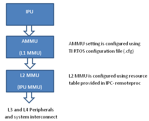
- PDK examples use addresses (0x4X000000) to peripheral registers and
use following MMU setting
- L2 MMU uses default 1:1 Mapping
- AMMU configuration translates physical 0x4X000000 access to logical 0x4X000000
- IPC+ Remote Proc ARM+M4 requires IPU to use logical address
(0x6X000000) and uses following MMU setting
- L2 MMU is configured such that MMU translates 0x6X000000 access to addresss 0x4X000000
- AMMU is configured for 1:1 mapping 0x6X000000 and 0x6X000000
Therefore after integrating IPC with PDK drivers, it is recommended that the alias addresses are used to access peripherals and PRCM registers. This requires changes to the addresses used by PDK drivers and in application code.
The following changes were then made to the IPU application source code:
Add UART_soc.c file to the project and modify the base addresses for all IPU UART register instance in the UART_HwAttrs to use alias addresses:
#ifdef _TMS320C6X
    CSL_DSP_UART3_REGS,
    OSAL_REGINT_INTVEC_EVENT_COMBINER,
#elif defined(__ARM_ARCH_7A__)
    CSL_MPU_UART3_REGS,
    106,
#else
    (CSL_IPU_UART3_REGS + 0x20000000),    //Base Addr = 0x48000000 + 0x20000000 = 0x68000000
    45,
#endif
Adding custom SOC configuration also means that you should use the generic UART driver instead of driver with built in SOC setup. To do this comment the following line in .cfg:
var Uart              = xdc.loadPackage('ti.drv.uart');
//Uart.Settings.socType = socType;
There is also an instance in the application code where we added pointer to PRCM registers that need to be changed as follows.
 CSL_l4per_cm_core_componentRegs *l4PerCmReg =
(CSL_l4per_cm_core_componentRegs \*) 0x6a009700; //CSL_MPU_L4PER_CM_CORE_REGS;
Now, you are ready to build the firmware. After the .out is built, change the extension to .xem4 and copy it over to the location in the filesystem that is used to load M4 firmware.
Download the Full CCS Project
3.7.4. IPC for AM65xx
Introduction
The AM65xx device has an MCU subsystem in addition to the Cortex-A53 cores. The MCU subsystem consists of 2 Cortex-R5F cores which can work as seperate cores or in lock-step mode.
This article is geared toward AM65xx users that are running Linux on the Cortex A53 core. The goal is to help users understand how to establish communication with the R5F cores.
There are many facets to this task: building, loading, debugging, memory sharing, etc. This article intends to take incremental steps toward understanding all of those pieces.
Software Dependencies to Get Started
Prerequisites
- Processor SDK Linux for AM65xx (Version 5.1 or newer needed)
- Processor SDK RTOS for AM65xx
- Code Composer Studio (choose version as specified on Proc SDK download page)
Note
Please be sure that you have the same version number for both Processor SDK RTOS and Linux.
For reference within the context of this wiki page, the Linux SDK is installed at the following location:
/mnt/data/user/ti-processor-sdk-linux-am65xx-evm-xx.xx.xx.xx
├── bin
├── board-support
├── docs
├── example-applications
├── filesystem
├── ipc-build.txt
├── linux-devkit
├── Makefile
├── Rules.make
└── setup.sh
The RTOS SDK is installed at:
/mnt/data/user/my_custom_install_sdk_rtos_am65xx_xx.xx
├── bios_6_xx_xx_xx
├── cg_xml
├── ctoolslib_x_x_x_x
├── framework_components_x_xx_xx_xx
├── gcc-linaro-<version>-x86_64_aarch64-elf
├── ipc_3_xx_xx_xx
├── ndk_3_xx_xx_xx
├── ns_2_xx_xx_xx
├── pdk_am65xx_x_x_x
├── processor_sdk_rtos_am65xx_x_xx_xx_xx
├── uia_2_xx_xx_xx
├── xdais_7_xx_xx_xx
├── xdctools_3_xx_xx_xx
Typical Boot Flow on AM65xx for ARM Linux users
AM65xx SOC’s have multiple processor cores - Cortex A53, ARM R5F cores. The A53 typically runs a HLOS like Linux/Android and the remote cores (R5Fs) run TI-RTOS. In the normal operation, boot loader(U-Boot/SPL) boots and loads the A53 with the HLOS. The A53 boots the R5 cores.

In this sequence, the interval between the Power on Reset and the remote cores (i.e. the R5Fs) executing is dependent on the HLOS initialization time.
Getting Started with IPC Linux Examples
The figure below illustrates how remoteproc/rpmsg driver from ARM Linux kernel communicates with IPC driver on slave processor (e.g. R5F) running RTOS.
In order to setup IPC on slave cores, we provide some pre-built examples in IPC package that can be run from ARM Linux. The subsequent sections describe how to build and run this examples and use that as a starting point for this effort.
Building the Bundled IPC Examples
The instructions to build IPC examples found under ipc_3_xx_xx_xx/examples/AM65XX_linux_elf have been provided in the Processor SDK IPC Quick Start Guide.
Let’s focus on one example in particular, ex02_messageq, which is located at <rtos-sdk-install-dir>/ipc_3_xx_xx_xx/examples/AM65XX_linux_elf/ex02_messageq. Here are the key files that you should see after a successful build:
├── r5f-0
│   └── bin
│       ├── debug
│       │   └── server_r5f-0.xer5f
│       └── release
│       │   └── server_r5f-0.xer5f
├── r5f-1
│   └── bin
│       ├── debug
│       │   └── server_r5f-1.xer5f
│       └── release
│       │   └── server_r5f-1.xer5f
├── host
│       ├── debug
│       │   └── app_host
│       └── release
│           └── app_host
Running the Bundled IPC Examples
On the target, let’s create a directory called ipc-starter:
root@am65xx-evm:~# mkdir -p /home/root/ipc-starter
root@am65xx-evm:~# cd /home/root/ipc-starter/
You will need to copy the ex02_messageq directory of your host PC to that directory on the target (through SD card, NFS export, SCP, etc.). You can copy the entire directory, though we’re primarily interested in these files:
- r5f-0/bin/debug/server_r5f-0.xer5f
- r5f-1/bin/debug/server_r5f-1.xer5f
- host/bin/debug/app_host
The remoteproc driver is hard-coded to look for specific files when loading the R5F cores. Here are the files it looks for:
- /lib/firmware/am65x-mcu-r5f0-fw
These are generally a soft link to the intended executable. So for example, let’s update the r5f0 executable on the target:
root@am65xx-evm:~# cd /lib/firmware/
root@am65xx-evm:/lib/firmware# ln -sf /home/root/ipc-starter/ex02_messageq/r5f-0/bin/debug/server_r5f-0.xer5f am65x-mcu-r5f0-fw
To reload R5F0 with this new executable, we perform the following steps:
First identify the remotproc node associated with R5F0. This can be done by:
root@am65xx-evm:/lib/firmware# grep -Isr r5f /sys/kernel/debug/remoteproc/
This will display for example:
/sys/kernel/debug/remoteproc/remoteproc8/resource_table:  Name trace:r5f0
/sys/kernel/debug/remoteproc/remoteproc8/name:41000000.r5f
then remoteproc8 is the node for the r5f core. ( Note the remoteprocx can change to for example remoteproc4):
root@am65xx-evm:~# echo stop > /sys/class/remoteproc/remoteproc4/state
[ 6663.636529] remoteproc remoteproc4: stopped remote processor 41000000.r5f

root@am65xx-evm:~# echo start > /sys/class/remoteproc/remoteproc4/state [ 6767.681165] remoteproc remoteproc4: powering up 41000000.r5f
[ 6767.803683] remoteproc remoteproc4: Booting fw image am65x-mcu-r5f0-fw, size 3590160
[ 6767.812558] platform 41000000.r5f: booting R5F core using boot addr = 0x0
[ 6767.821345] virtio_rpmsg_bus virtio0: rpmsg host is online
[ 6767.827147] remoteproc remoteproc4: registered virtio0 (type 7)
[ 6767.834776] remoteproc remoteproc4: remote processor 41000000.r5f is now up
root@am65xx-evm:~# [ 6767.848838] virtio_rpmsg_bus virtio0: creating channel rpmsg-proto addr 0x3d
More info related to loading firmware to the various cores can be found here.
Finally, we can run the example on R5 core:
root@am65xx-evm:~# ./app_host R5F-0
--> main:
--> Main_main:
--> App_create:
App_create: Host is ready
<-- App_create:
--> App_exec:
App_exec: sending message 1
App_exec: sending message 2
App_exec: sending message 3
App_exec: message received, sending message 4
App_exec: message received, sending message 5
App_exec: message received, sending message 6
App_exec: message received, sending message 7
App_exec: message received, sending message 8
App_exec: message received, sending message 9
App_exec: message received, sending message 10
App_exec: message received, sending message 11
App_exec: message received, sending message 12
App_exec: message received, sending message 13
App_exec: message received, sending message 14
App_exec: message received, sending message 15
App_exec: message received
App_exec: message received
App_exec: message received
<-- App_exec: 0
--> App_delete:
<-- App_delete:
<-- Main_main:
<-- main:
root@am65xx-evm:~#
Understanding the Memory Map
Overall Linux Memory Map
root@am65xx-evm:~# cat /proc/iomem
[snip...]
    80000000-9affffff : System RAM
    80080000-80b2ffff : Kernel code
    80bb0000-80d9ffff : Kernel data
    9c800000-9e7fffff : System RAM
    a0000000-ffffffff : System RAM
    400000000-4ffffffff : /soc0/fss@47000000/ospi@47040000
    880000000-8ffffffff : System RAM
DMA memory Carveouts
root@am65xx-evm:~# dmesg | grep  "Reserved memory"
[    0.000000] Reserved memory: created DMA memory pool at 0x000000009b000000, size 16 MiB
[    0.000000] Reserved memory: created DMA memory pool at 0x000000009c000000, size 8 MiB
From the output above, we can derive the location and size of each DMA carveout:
| Memory Section | Physical Address | Size |
|---|---|---|
| R5F-0 Pool | 0x9c000000 | 8 MB |
| R5F-1 Pool | 0x9b000000 | 16 MB |
For details on how to adjust the sizes and locations of the R5F Pool carveouts, please see the corresponding section for changing the R5F memory map.
Changing the R5F Memory Map
Slave Physical Addresses
The physical location where the R5F code/data will actually reside is defined by the DMA carveout. To change this location, you must change the definition of the carveout. The R5F carveouts are defined in the Linux dts file. For example for the AM65xx EVM:
reserved-memory {
                #address-cells = <2>;
                #size-cells = <2>;
                ranges;

                r5f1_memory_region: r5f1-memory@9b000000 {
                        compatible = "shared-dma-pool";
                        reg = <0 0x9b000000 0 0x1000000>;
                        no-map;
                };

                r5f0_memory_region: r5f0-memory@9c000000 {
                        compatible = "shared-dma-pool";
                        reg = <0 0x9c000000 0 0x800000>;
                        no-map;
                };

                secure_ddr: secure_ddr@9e800000 {
                        reg = <0 0x9e800000 0 0x01800000>; /* for OP-TEE */
                        alignment = <0x1000>;
                        no-map;
                };
        };
You are able to change both the size and location. Be careful not to overlap any other carveouts!
Additionally, when you change the carveout location, there is a corresponding change that must be made to the resource table. For starters, if you’re making a memory change you will need a custom resource table. The resource table is a large structure that is the “bridge” between physical memory and virtual memory. There is detailed information available in the article IPC Resource customTable.
Once you’ve created your custom resource table, you must update the address of PHYS_MEM_IPC_VRING to be the same base address as your corresponding CMA.
#define R5F_MEM_TEXT            0x9C200000
#define R5F_MEM_DATA            0x9C300000

#define R5F_MEM_IPC_DATA        0x9C100000
#define R5F_MEM_IPC_VRING       0x9C000000
#define R5F_MEM_RPMSG_VRING0    0x9C000000
#define R5F_MEM_RPMSG_VRING1    0x9C010000
#define R5F_MEM_VRING_BUFS0     0x9C040000
#define R5F_MEM_VRING_BUFS1     0x9C080000
Note
The PHYS_MEM_IPC_VRING definition from the resource table must match the address of the associated CMA carveout!
R5 Virtual Addresses
These addresses are the ones seen by the MCU subsystem, i.e. these will be the addresses in your linker command files, etc.
You must ensure that the sizes of your sections are consistent with the corresponding definitions in the resource table. You should create your own resource table in order to modify the memory map. This is describe in the wiki page IPC Resource customTable. You can look at an existing resource table inside IPC:
ipc/packages/ti/ipc/remoteproc/rsc_table_am65xx_r5f.h
{
     TYPE_CARVEOUT,
     R5F_MEM_IPC_DATA, 0,
     R5F_MEM_IPC_DATA_SIZE, 0, 0, "R5F_MEM_IPC_DATA",
 },

 {
     TYPE_CARVEOUT,
     R5F_MEM_TEXT, 0,
     R5F_MEM_TEXT_SIZE, 0, 0, "R5F_MEM_TEXT",
 },

 {
     TYPE_CARVEOUT,
     R5F_MEM_DATA, 0,
     R5F_MEM_DATA_SIZE, 0, 0, "R5F_MEM_DATA",
 },

 {
     TYPE_TRACE, TRACEBUFADDR, TRACEBUFSIZE, 0, "trace:r5f0",
 },
Let’s have a look at some of these to understand them better. For example:
{
    TYPE_CARVEOUT,
    DSP_MEM_TEXT, 0,
    DSP_MEM_TEXT_SIZE, 0, 0, "DSP_MEM_TEXT",
},
Key points to note are:
- The “TYPE_CARVEOUT” indicates that the physical memory backing this entry will come from the associated reserved pool.
- DSP_MEM_TEXT is a #define earlier in the code providing the address for the code section. It is 0x9C200000 by default. This must correspond to a section from your DSP linker command file, i.e. EXT_CODE (or whatever name you choose to give it) must be linked to the same address.
- DSP_MEM_TEXT_SIZE is the size of the text section. The actual amount of linked code in the corresponding section of your executable must be less than or equal to this size.
Let’s take another:
{
    TYPE_TRACE, TRACEBUFADDR, TRACEBUFSIZE, 0, "trace:r5f0",
},
Key points are:
- The “TYPE_TRACE” indicates this is for trace info.
- The TRACEBUFADDR is defined earlier in the file as &ti_trace_SysMin_Module_State_0_outbuf__A. That corresponds to the symbol used in TI-RTOS for the trace buffer.
- The TRACEBUFSIZE is the size of the Trace section The corresponding size
in the cfg file should be the same (or less). It looks like this:
SysMin.bufSize = 0x8000;
3.7.5. IPC for K2x
3.7.5.1. Introduction
This article is geared toward 66AK2x users that are running Linux on the Cortex A15. The goal is to help users understand how to gain access to the DSP (c66x) subsystem of the 66AK2x. While the examples used in this guide are specific to K2G, the information provided here applies to all K2x platforms.
3.7.5.2. Software Dependencies to Get Started
Prerequisites
- Processor SDK Linux for K2G
- Processor SDK RTOS for K2G
- Code Composer Studio (choose version as specified on Proc SDK download page)
Note
Please be sure that you have the same version number for both Processor SDK RTOS and Linux.
For reference within the context of this page, the Linux SDK is installed at the following location:
/mnt/data/user/ti-processor-sdk-linux-k2g-evm-xx.xx.xx.xx
    ├── bin
    ├── board-support
    ├── docs
    ├── example-applications
    ├── filesystem
    ├── linux-devkit
    ├── linux-devkit.sh
    ├── Makefile
    ├── Rules.make
    └── setup.sh
The RTOS SDK is installed at the following location:
/mnt/data/user/my_custom_install_sdk_rtos_k2g_xx_xx.xx
    ├── bios_6_xx_xx_xx
    ├── cg_xml
    ├── ctoolslib_x_x_x_x
    ├── dsplib_c66x_x_x_x_x
    ├── edma3_lld_x_xx_x_xxx
    ├── framework_components_x_xx_xx_xx
    ├── gcc-arm-none-eabi-6-2017-q1-update
    ├── imglib_c66x_x_x_x_x
    ├── ipc_3_xx_xx_xx
    ├── mathlib_c66x_x_x_x_x
    ├── multiprocmgr_x_x_x_x
    ├── ndk_3_xx_xx_xx
    ├── openmp_dsp_k2g_2_xx_xx_xx
    ├── pdk_k2g_x_x_xx
    ├── processor_sdk_rtos_k2g_x_xx_xx_xx
    ├── uia_2_xx_xx_xx
    ├── xdais_7_xx_xx_xx
    ├── xdctools_3_xx_xx_xx
3.7.5.3. Multiple Processor Manager
The Multiple Processor Manager (MPM) module is used to load and run DSP images from the ARM. The following section provides some more detail on the MPM.
- The MPM has the two following major components:
- MPM server (mpmsrv): It runs as a daemon and runs automatically in the default filesystem supplied in Processor SDK. It parses the MPM configuration file from /etc/mpm/mpm_config.json, and then waits on a UNIX domain socket. The MPM server runs and maintains a state machine for each slave core.
- MPM command line/client utility (mpmcl): It is installed in the filesystem and provides command line access to the server.
- The following are the different methods that can be used by MPM to load and run slave images:
- Using mpmcl utility.
- From the config file, to load at bootup.
- Writing an application to use mpmclient header file and library.
- The location of the mpm server/daemon logs is based on the “outputif” configuration in the JSON config file. By default, this is /var/log/syslog.
- The load command writes the slave image segments to memory using UIO interface. The run command runs the slave images.
- All events from the state transition diagram are available as options of mpmcl command, except for the crash event.
- The reset state powers down the slave nodes.
Software Flow Diagram Slave States in MPM
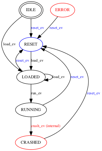
3.7.5.3.1. Methods to load and run ELF images using MPM
Using mpmcl utility to manage slave processors
Use mpmcl –help for details on the supported commands. The following is the output of mpmcl help:
Usage: mpmcl <command> [slave name] [options]
Multiproc manager CLI to manage slave processors
<command>           Commands for the slave processor
             Supported commands: ping, load, run, reset, status, coredump, transport
                                 load_withpreload, run_withpreload
[slave name]        Name of the slave processor as specified in MPM config file
[options]           In case of load, the option field need to have image file name
The following is a sample set of mpmcl commands for managing slave processors:
| Command | Description |
|---|---|
| mpmcl ping | Ping daemon if it is alive |
| mpmcl status dsp0 | Check status of dsp core 0 |
| mpmcl load dsp0 dsp-core0.out | Load dsp core 0 with an image |
| mpmcl run dsp0 | Run dsp core 0 |
| mpmcl reset dsp0 | Reset dsp core 0 |
| mpmcl load_withpreload dsp0 preload_image.out dsp-core0.out | Load dsp core 0 image with a preload image |
| mpmcl run_withpreload dsp0 | Run dsp core 0 with preload |
Note
In the case of an error, the mpm server takes the slave to error state. You need to run the reset command to change back to idle state so that the slave can be loaded and run again.
Note
The idle status of the slave core means the slave core is not loaded as far as MPM is concerned. It does NOT mean the slave core is running idle instructions.
Loading and running slave images at bootup
The config file can load a command script to load and run slave cores at bootup. The path of the script is to be added in “cmdfile”: “/etc/mpm/slave_cmds.txt” in the config file. The following is a sample command to load and run DSP images:
dsp0 load ./dsp-core0.out
dsp1 load ./dsp-core0.out
dsp0 run
dsp1 run
Managing slave processors from application program
An application can include mpmclient.h from the MPM package and link to libmpmclient.a to load/run/reset slave cores. The mpmcl essentially is a wrapper around this library to provide command line access for the functions from mpmclient.h.
DSP Image Requirements
For MPM to properly load and manage a DSP image, the following is required:
- The DSP image should be in ELF format.
- The MPM ELF loader loads those segments to DSP memory, whose PT_LOAD field is set. In order to skip loading of a particular section, set the type to NOLOAD in the command/cfg file.
/* Section not to be loaded by remoteproc loader */
Program.sectMap[".noload_section"].type = "NOLOAD";
- The default allowed memory ranges for DSP segments are as follows:
| Start Address | Length | |
|---|---|---|
| L2 Local | 0x00800000 | 1MB |
| L2 Global | 0x[1-4]0800000 | 1MB |
| MSMC | 0x0C000000 | 6MB |
| DDR3 | 0xA0000000 | 512MB |
The segment mapping can be changed using the mpm_config.json and Linux kernel device tree.
3.7.5.4. Getting Started with IPC Linux Examples
The figure below illustrates how remoteproc/rpmsg driver from ARM Linux kernel communicates with IPC driver on slave processor (e.g. DSP) running RTOS.
In order to setup IPC on slave cores, we provide some pre-built examples in IPC package that can be run from ARM Linux. The subsequent sections describe how to build and run this examples and use that as a starting point for this effort.
3.7.5.4.1. Building the Bundled IPC Examples
The instructions to build IPC examples found under ipc_3_xx_xx_xx/examples/66AK2G_linux_elf have been provided in the Processor SDK IPC Quick Start Guide.
Let’s focus on one example in particular, ex02_messageq, which is located at <rtos-sdk-install-dir>/ipc_3_xx_xx_xx/examples/66AK2G_linux_elf/ex02_messageq.
Here are the key files that you should see after a successful build:
├── core0
│   └── bin
│       ├── debug
│       │   └── server_core0.xe66
│       └── release
│           └── server_core0.xe66
├── host
│   └── bin
│       ├── debug
│       │   └── app_host
│       └── release
│       │   └── app_host
3.7.5.4.2. Running the Bundled IPC Examples
You will need to copy the ex02_messageq executable binaries onto the target (through SD card, NFS export, SCP, etc.). You can copy the entire ex02_messageq directory, though we’re primarily interested in these executable binaries:
- Core0/bin/debug/ server_core0.xe66
- host/bin/debug/app_host
The Multi-Processor Manager (MPM) Command Line utilities are used to download and start the DSP executables.
Let’s load the example and run the DSP:
root@k2g-evm:~# mpmcl reset dsp0
root@k2g-evm:~# mpmcl status dsp0
root@k2g-evm:~# mpmcl load dsp0 server_core0.xe66
root@k2g-evm:~# mpmcl run dsp0
You should see the following output:
[  919.637071] remoteproc remoteproc0: powering up 10800000.dsp
[  919.650495] remoteproc remoteproc0: Booting unspecified pre-loaded fw image
[  919.683836] virtio_rpmsg_bus virtio0: rpmsg host is online
[  919.689355] virtio_rpmsg_bus virtio0: creating channel rpmsg-proto addr 0x3d
[  919.712755] remoteproc remoteproc0: registered virtio0 (type 7)
[  919.718671] remoteproc remoteproc0: remote processor 10800000.dsp is now up
Now, we can run the IPC example:
root@k2g-evm:~# ./app_host CORE0
The following is the expected output:
--> main:
--> Main_main:
--> App_create:
App_create: Host is ready
<-- App_create:
--> App_exec:
App_exec: sending message 1
App_exec: sending message 2
App_exec: sending message 3
App_exec: message received, sending message 4
App_exec: message received, sending message 5
App_exec: message received, sending message 6
App_exec: message received, sending message 7
App_exec: message received, sending message 8
App_exec: message received, sending message 9
App_exec: message received, sending message 10
App_exec: message received, sending message 11
App_exec: message received, sending message 12
App_exec: message received, sending message 13
App_exec: message received, sending message 14
App_exec: message received, sending message 15
App_exec: message received
App_exec: message received
App_exec: message received
<-- App_exec: 0
--> App_delete:
<-- App_delete:
<-- Main_main:
<-- main:
3.7.5.5. Understanding the Memory Map
3.7.5.5.1. Overall Linux Memory Map
root@k2g-evm:~# cat /proc/iomem
[snip...]
80000000-8fffffff : System RAM (boot alias)
92800000-97ffffff : System RAM (boot alias)
9d000000-ffffffff : System RAM (boot alias)
800000000-80fffffff : System RAM
        800008000-800dfffff : Kernel code
        801000000-80109433b : Kernel data
812800000-817ffffff : System RAM
818000000-81cffffff : CMEM
81d000000-87fffffff : System RAM
CMA Carveouts
To view the allocation at run-time:
root@k2g-evm:~# dmesg | grep "Reserved memory"
[    0.000000] Reserved memory: created CMA memory pool at 0x000000081f800000, size 8 MiB
The CMA block is defined in the following file for the K2G EVM:
linux/arch/arm/boot/dts/keystone-k2g-evm.dts
CMEM
To view the allocation at run-time:
root@k2g-evm:~# cat /proc/cmem
Block 0: Pool 0: 1 bufs size 0x5000000 (0x5000000 requested)
Pool 0 busy bufs:
Pool 0 free bufs:
id 0: phys addr 0x818000000
This shows that we have defined a CMEM block at physical address 0x818000000 with total size 0x5000000. This block contains a buffer pool consisting of 1 buffer. Each buffer in the pool (only one in this case) is defined to have a size of 0x5000000.
The CMEM block is defined in the following file for the K2G EVM:
linux/arch/arm/boot/dts/k2g-evm-cmem.dtsi
3.7.5.6. Changing the DSP Memory Map
3.7.5.6.1. Linux Device Tree
The carveouts for the DSP are defined in the Linux dts file. For the K2G EVM, these definitions are located in linux/arch/arm/boot/dts/keystone-k2g-evm.dts
reserved-memory {
        #address-cells = <2>;
        #size-cells = <2>;
        ranges;

        dsp_common_mpm_memory: dsp-common-mpm-memory@81d000000 {
                compatible = "ti,keystone-dsp-mem-pool";
                reg = <0x00000008 0x1d000000 0x00000000 0x2800000>;
                no-map;
                status = "okay";
        };
        dsp_common_memory: dsp-common-memory@81f800000 {
                compatible = "shared-dma-pool";
                reg = <0x00000008 0x1f800000 0x00000000 0x800000>;
                reusable;
                status = "okay";
        };
};
The memory region “dsp_common_mpm_memory” starts at address 0x9d000000 and has a size of 0x2800000 bytes. This region is where the DSP code/data needs to reside. If they are not in this region, you will see the error “load failed (error: -104)” when trying to load.
The memory region “dsp_common_memory” starts at address 0x9f800000 and has a size of 0x800000. This is a CMA pool, as indicated by the line “compatible = “shared-dma-pool”;”, and is reserved for Virtque region and Rpmsg vring buffers.
As of Processor SDK 5.2, the Virtque and vring buffers are allocated by the remoteproc driver from this region and communicated to the slave by update to the resource table.
3.7.5.6.2. Resource Table
The default resource table for K2G is located at ipc_3_xx_xx_xx/packages/ti/ipc/remoteproc/rsc_table_tci6638.h
The resource table contains the definitions of the CMA carveout for the Rpmsg vring buffers.
3.7.5.6.3. MPM Config File
The MPM configuration file is a JSON format configuration file and is located in the default root file system release as part of Processor SDK Linux. It is labeled “mpm_config.json” and is located in /etc/mpm.
The following are some details regarding the MPM configuration file:
- The MPM parser ignores any JSON elements which it does not recognize. This can be used to put comments in the config file.
- The tag cmdfile (which is commented as _cmdfile by default) loads and runs MPM commands at bootup.
- The tag outputif can be syslog, stderr or filename if it does not match any predefined string.
- By default, the config file allows loading of DSP images to L2, MSMC and DDR. It can be changed to add more restrictions on loading, or to load to L1 sections.
- In current form, MPM does not do MPAX mapping for local to global addresses and the default MPAX mapping is used.
- By default, the MPM configuration file configures the MSMC region with start address at 0x0c000000 and size of 0x600000 bytes, and the DDR region with start address of 0xa0000000 and size of 0x10000000 bytes, as seen in the snippet below.
{
        "name": "local-msmc",
        "globaladdr": "0x0c000000",
        "length": "0x600000",
        "devicename": "/dev/dspmem"
},
{
        "name": "local-ddr",
        "globaladdr": "0xa0000000",
        "length": "0x10000000",
        "devicename": "/dev/dspmem"
},
3.7.5.6.4. Config.bld
The config.bld file is used by the IPC examples to configure the external memory map at the application level. It is located in /ipc_3_x_x_x/examples/66AK2G_linux_elf/ex02_messageq/shared/. A linker command file can be used as well, in place of a config.bld file, to place sections into memory.
By default, the ex02_messageq runs from MSMC memory so the config.bld file is not used. In the next section, we will show how to modify the config.bld to place the DSP code in DDR.
3.7.5.7. Modifying ex02_messageQ example to run from DDR
As an example, the following section shows how to modify the IPC memory map to run the ex02_messageq example from DDR instead of MSMC.
Changes to Config.bld
We want to place the DSP application in DDR instead of MSMC, so we need to make the following changes to the config.bld file.
Remove the following lines:
    Build.platformTable["ti.platforms.evmTCI66AK2G02:core0"] = {
externalMemoryMap: [ ]
    };
and add the following:
var evmTCI66AK2G02_ExtMemMapDsp = {
        EXT_DDR: {
                name: "EXT_DDR",
                base: 0x9d000000,
                len:  0x00100000,
                space: "code/data",
                access: "RWX"
        },
};

Build.platformTable["ti.platforms.evmTCI66AK2G02:core0"] = {
        externalMemoryMap: [
                [ "EXT_DDR", evmTCI66AK2G02_ExtMemMapDsp.EXT_DDR ],
        ],
        codeMemory: "EXT_DDR",
        dataMemory: "EXT_DDR",
        stackMemory: "EXT_DDR",
};
This will place the DSP code, data, and stack memory at address 0x9d000000. We have chosen address 0x9d000000 because that is what is defined in the Linux device tree by default. Refer to the “dsp_common_mpm_memory” block in the previous section “Linux Device Tree.” Note, the length specified here is 0x00100000; this must be less than the size of the dsp_common_mpm_memory pool.
Changes to the MPM Config File
By default, mpm_config.json defines the DDR region to start at 0xa0000000 with a length of 0x10000000. We need to change this to include the region where our application resides so we will change it to span from 0x90000000 to 0xc0000000. This can be increased as needed by the application.
To do this, change the following block from:
{
        "name": "local-ddr",
        "globaladdr": "0xa0000000",
        "length": "0x10000000",
        "devicename": "/dev/dsp0"
},
To:
{
        "name": "local-ddr",
        "globaladdr": "0x90000000",
        "length": "0x30000000",
        "devicename": "/dev/dsp0"
},
Changes to Core0.cfg
Remove the following lines:
Program.sectMap[".text:_c_int00"] = new Program.SectionSpec();
Program.sectMap[".text:_c_int00"].loadSegment = "L2SRAM";
Program.sectMap[".text:_c_int00"].loadAlign = 0x400;
These lines above place the .text section into L2SRAM. We want it to be in DDR so it needs to be removed.
Remove the following lines:
var Resource = xdc.useModule('ti.ipc.remoteproc.Resource');
Resource.loadSegment = Program.platform.dataMemory;
These lines place the resource table into the dataMemory section, which in our case is in DDR memory.
The Remoteproc driver requires the trace buffers and resource table to be placed into L2SRAM. If they are not, you will see the following error when loading:
keystone-rproc 10800000.dsp: error in ioctl call: cmd 0x40044902
(2), ret -22
load failed (error: -107)
So we will need to add the following lines to place the trace buffer and resource table into L2SRAM:
Program.sectMap[".far"] = new Program.SectionSpec();
Program.sectMap[".far"].loadSegment = "L2SRAM";
Program.sectMap[".resource_table"] = new Program.SectionSpec();
Program.sectMap[".resource_table"].loadSegment = "L2SRAM";
var Resource = xdc.useModule('ti.ipc.remoteproc.Resource');
Resource.loadSegment = "L2SRAM"
Disable OpenCL application
The OpenCL application that runs by default needs to be disabled since it interferes with the caching properties of the memory region used by our modified example. If it is not disabled, the application will hang at App_create(). It can be disabled by issuing the following command:
root@k2g-evm:~# systemctl disable ti-mct-daemon.service
Run the Example
After power-cycling the EVM, we can now load and run the example:
mpmcl reset dsp0
mpmcl load dsp0 server_core0.xe66
mpmcl run dsp0
./app_host CORE0
3.7.5.8. Loading DSP images from CCS (without using MPM)
By default, the DSP cores are powered down by u-boot at the time of EVM boot. After kernel is running, MPM can be used to load and run DSP images from Linux command-line/utility.
Rather than using MPM, if you want to use CCS to load and run DSP images, then set the following setting in u-boot prompt:
setenv debug_options 1
saveenv
reset
This will not power down DSPs at startup and CCS/JTAG can connect to the DSP for loading and debugging. This option is useful if you want to boot Linux on ARM and then use JTAG to manually load and run the DSPs. Otherwise you may see “held in reset” errors in CCS.
Note
The above step is not needed if you want to load DSP cores using MPM and subsequently use CCS to connect to DSP.
3.7.5.9. MPM Debugging
The following are some pointers for MPM debugging.
MPM Error Codes
- If MPM server crashed/exited/not running in the system, mpmcl ping will return failure
- If there is any load/run/reset failure MPM client provides error codes. The major error codes are given below.
| error code | error type |
|---|---|
| -100 | error_ssm_unexpected_event |
| -101 | error_ssm_invalid_event |
| -102 | error_invalid_name_length |
| -103 | error_file_open |
| -104 | error_image_load |
| -105 | error_uio |
| -106 | error_image_invalid_entry_address |
| -107 | error_resource_table_setting |
| -108 | error_error_no_entry_point |
| -109 | error_invalid_command |
- The MPM daemon logs goes to /var/log/syslog by default. This file can provide more information on the errors.
DSP trace/print messages from Linux
The DSP log messages can be read from following debugfs locations:
DSP log entry for core #: /sys/kernel/debug/remoteproc/remoteproc#/trace0
Where # is the core id starting from 0.
root@keystone-evm:~# cat /sys/kernel/debug/remoteproc/remoteproc0/trace0
Main started on core 1
....
root@keystone-evm:~#
3.7.5.9.1. Detecting crash event in MPM
In the case of a DSP exception, the MPM calls the script provided in JSON config file. The Processor SDK Linux filesystem has a sample script /etc/mpm/crash_callback.sh that sends message to syslog indicating which core crashed. This script can be customized to suit notification needs.
Generating DSP coredump
The DSP exceptions can be any of the following:
- Software-generated exceptions
- Internal/external exceptions
- Watchdog timer expiration
The MPM creates an ELF formatted core dump.
root@keystone-evm:~# mpmcl coredump dsp0 coredump.out
The above command will generate a coredump file with name coredump.out for the DSP core 0.
Note
The coredump can be captured from a running system that is not crashed, in this case the register information won’t be available in the coredump.
3.7.5.10. Frequently Asked Questions
Q: How to maintain cache coherency
A: In the first 2GB of DDR, region 00 8000 0000 - 00 FFFF FFFF (alias of 08 0000 0000 - 08 7FFF FFFF), no IO coherency is supported. Cache coherency will need to be maintained by software. The cache coherence API descriptions for the A15 can be found in the TI-RTOS Cache Module cdocs.
Q: MPM does not load and run the DSP image
A: There can be several scenarios, the following are a few of them:
- The MPM server may not be running. The command mpmcl ping will timeout in this case. The mpm server is expected to be running in the background to service the requests from mpm client. The log file /var/log/mpmsrv.log can provide more information.
- An issue can be the devices relevant to MPM /dev/dsp0, ... , /dev/dsp7, /dev/dspmem are not created. You need to check if these devices are present. If they are not present then check if the kernel and device tree have right patches for these devices.
- The log can print error codes provided in MPM error codes section.
- Another way to debug loading issues is, to run mpm server in non-daemon mode from one shell using command mpmsrv -n, before this you need to kill the server if it is running. (The command to kill is mpmsrv -k or you can choose to kill the process). Then from other shell run the client operations.
Q: MPM fails to load the segments
A: The MPM fundamentally copies segments from DSP image to memory using a custom UIO mmap interface. Each local or remote node (DSPs) is allocated some amount of resources using the config file. The segments in the config file needs to be subset of memory resources present in kernel dts file. The system integrator can choose to add or change memory configurations as needed by application. In order to change the default behavior user need to change in JSON config file and kernel device tree. In JSON configuration file, the segments section need to be updated. You need to make sure it does not overlap the scratch memory section. You might have to move the scratch section if the allocated DDR size is increased. And, in the kernel device tree the mem sections of dsp0, .. , dsp7, dspmem need to be updated.
- Sometimes few segments used by DSP may not accessible by ARM at the time of loading. These segment can cause load failure. So it is useful to understand the memory layout of your own application and if there are any such sections, you can skip loading those segments to memory using NOLOAD method described above.
- The MPM does not have MPAX support yet. So the MPAX support needs to be handled by application.
- If the linker adds a hole in the resource table section right before the actual resource_table due to the alignment restriction, then MPM as of now won’t be able to skip the hole and might get stuck. In this case if you hex-dump resource table (method given below) size will be quite large (normally for a non-IPC case it is around 0xac). The workaround is to align the .resource_table section to 0x1000 using linker command file or some other method so that linker does not add any hole in the resource_table section. In future, MPM will take care of this offset.
Q: MPM fails to run the image
A: MPM takes DSP out of reset to run the image. So, the fails to run normally attributed to DSP is crashing before main or some other issue in the image. But, to debug such issue, after mpmcl run, use CCS to connect to the target and then do load symbols of the images. Then the DSP can be debugged using CCS. Another way to debug the run issue, is to aff a infinite while loop in the reset function so that the DSP stops at the very beginning. Then load and run the DSP using MPM and connect thru CCS, do load symbols and come out of while loop and debug.
Q: I don’t see DSP prints from debugfs
A: Make sure you followed the procedure described above to include the resource table in the image. Care should be taken for the resource table not being compiled out by linker. To check if the resource table present in the image using command readelf –hex-dump=.resource_table <image name>. It should have some non-zero data. Another point is, if you are loading same image in multiple cores and if the resource table and trace buffer segments overlap with each other in memory, then there can be undesirable effect.
Q: I see the DSP state in /sys/kernel/debug/remoteproc/remoteproc0/state as crashed
A: The file /sys/kernel/debug/remoteproc/remoteproc#/state does not indicate state of DSP when MPM is used for loading. The state of the DSP can be seen using MPM client. See the description of the command in Methods to load and run ELF images using MPM sections.
3.7.6. Multiple Ways of ARM-DSP Communication
This document describes the ways of communication on TI multicore devices. The individual cores in an applicatioin can assume the roles of Host/Device or Master/Slave. This discussion here assumes the Host/Master is ARM® cluster running SMP/Linux and the Device/Slave is the C6xx DSP cluster running TI-RTOS.
OpenCL
OpenCL is a framework for writing programs that execute across heterogeneous systems, and for expressing programs where parallel computation is dispatched across heterogeneous devices. It is an open, royalty-free standard managed by Khronos consortium. On a heterogeneous SoC, OpenCL views one of the programmable cores as a host and the other cores as devices. The application running on the host (i.e. the host program) manages execution of code (kernels) on the device and is also responsible for making data available to the device. A device consists of one or more compute units. On the ARM and DSP SoCs, each C66x DSP is a compute unit. The OpenCL runtime consists of two components: (1) An API for the host program to create and submit kernels for execution and (2) A cross-platform language for expressing kernels – OpenCL C – which is based on C99 C with some additions and restrictions OpenCL supports both data parallel and task parallel programming paradigms. Data parallel execution parallelizes the execution across compute units on a device. Task parallel execution enables asynchronous dispatch of tasks to each compute unit. For more info, please refer to OpenCL User’s Guide
Use Cases
- Offload computation from ARM running Linux or RTOS to the DSPs
Examples
Please see OpenCL examples
Benefits
- Easy porting between devices
- No need to understand memory architecture
- No need to worry about MPAX and MMU
- No need to worry about coherency
- No need to build/configure/use IPC between ARM and DSP
- No need to be an expert in DSP code, architecture, or optimization
Drawbacks
- Don’t have control on system memory layout, etc. to handle optimize DSP code
DCE (Distributed Codec Engine)
DCE Framework provides an easy way for users to write applications on devices, such as AM57xx, having hardware accelerators for image and video. It eanbles and provides remote access to hardware acceleration for audio and video encoding and decoding on the slave cores. The ARM user space GStreamer based multimedia application uses GStreamer library to load and interface with TI GStreamer plugin which handles all the details specific to use of the hardware accelerator. The plugin interfaces libdce module that provides the ARM user space API. Libdce uses RPMSG framework on the ARM which communicates to the counterpart on the slave core. On the slave core, it uses Codec engine and Frame Component for the video/image codec processing on IVA.
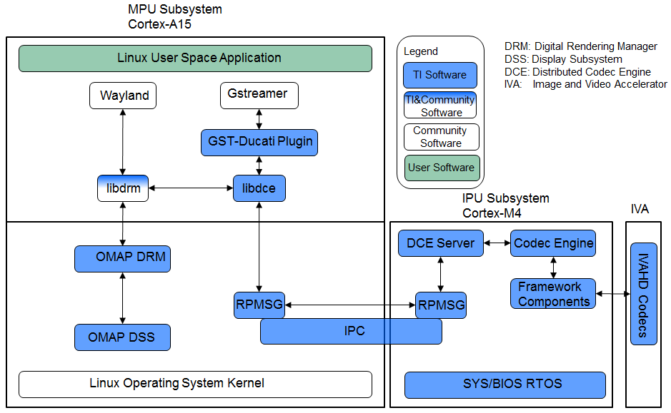
Overview of the Multimedia Software Stack using DCE AM57xx as an example has the following accelerators
- Image and Video Accelerator (IVA)
- Video Processing Engine (VPE)
- C66x DSP cores for offloading certain image/video and/or voice/audio processing
Users can leverate open source elements that provide functionality such as AVI stream demuxing, and audio codec, etc. These along with the ARM based GStreamer plugins in TI’s Processor Linux SDK provide the abstracts for the accelerator offload.
In AM57xx, the hardware accelerators are capable of the following
- IVA for multimedia enconding and decoding
- Video Decode: H264, MPEG4, MPEG2, and VC1
- video Encode: H264, and MPEG4
- Image Decode: MJPEG
- VGE for video operations such as scaling, color space conversion, and
deinterlacing of the following formats:
- Supported Input formats: NV12, YUYV, UYVY
- Supported Output formats: NV12, YUYV, UYVY, RGB24, ARGB24, and ABGR24
- DSP for offloading signal processing
- Sample Image Processing Kernels integrated in the DSP gstreamer plugin: Median2x2, Median3x3, Sobel3x3, Conv5x5, Canny
For more info, please refer to the DCE Developer’s Guide or DCE for Multimedia
Use Cases
- audio/video or proprietary codecs processing offload to slave core
Examples
- Please see sample application
Benefits
- Accelerated multimedia codec processing
- Simplifies the development of multimedia application when interfacing with Gstreamer and TI Gstreamer plugin
Drawbacks
- Not suitable for non-codec algorithm
- Need work to add new codec algorithm
- Need knowledge of DSP programming
Big Data IPC
Big Data is a special use case of TI IPC implementation for High Performance Computing applications and other Data intensive applications which often require passing of big data buffers between the multi-core processors in an SoC. The Big Data IPC provides a high level abstraction to take care of address translation and Cache sync on the big data buffers
Use Cases
- Message/Data exchange for size greater than 512 bytes between ARM and DSP
Examples
- Please see Big Data IPC example
Benefits
- Capable of handling data greater than 512 bytes
Drawbacks
- Need knowledge of DSP memory architecture
- Need knowledge of DSP configuration and programming
- TI proprietary API
IPC
Inter-Processor Communication (IPC) is a set of modules designed to faciliate inter-process communication. The communication includes message passing, streams, and linked lists. The modules provides services and functions which can be used for communication between ARM and DSP processors in a multi-processor environment.
- IPC Module initialized the various subsystems of IPC and synchronizes multiple processors.
- MessageQ Module supports the structured sending and receiving of variable length messages.
- ListMP Module is a linked-list based module designed to provide a mean of communication between different processors. It uses shared memory to provide a way for multiple processors to share, pass or store data buffers, messages,
or state information.
- HeapMP Module provides 3 types of memory management, fixed-size buffers, multiple different fixed-size buffers, and variable-size buffers.
- GateMP Module enforces both local and remote context protection through its instance.
- NOtify Module manages the multiplexing/demultiplexing of software interrupts over hardware interrupts.
- SharedRegion Module is designed to be used in a multi-processor environment where there are memory regions that are shared and accessed across different processors.
- List Module provides support for creating doubly-linked lists of objects
- MultiProc Module centralizes processor ID management into one module in a multi-processor environment.
- NameServer Module manages local name/value pairs which enables an application and other modules to sotre and retrieve values based on a name.
User Cases
- Message/Data exchange between ARM and DSP
Examples
- Please see IPC Examples
Benefits
- suitable for those who are familiar with DSP programming
- DSP code optimization
Drawbacks
- Need knowledge of DSP memory architecture
- Need knowledge of DSP configuration and programming
- message size is limited to 512 bytes
- TI proprietary API
Pros and Cons
| Pros | Cons | |
|---|---|---|
| OpenCL | Easy porting No DSP programming Standard OpenCL APIs | Customer don’t have control over memory layout etc. to handle optimize DSP code |
| DCE | Accelerated multimedia codec handling Simplifies development when interfacing with GStreamer | Not meant for non-codec algorithms Need work to add new codec algorithms Codec like APIs Require knowledge of DSP programming |
| Big Data | Full control of DSP configuration Capable of DSP code optimization Not limited to the 512 byte buffer size Same API supported on multiple TI platforms | Need to know memory architecture Need to know DSP configuration and programming TI proprietary API |
| IPC | Full control of DSP configuration Capable of DSP code optimization Same API supported on multiple TI platforms | Need to know memory architecture Need to know DSP configuration and programming Limited to small messages (less than 512 bytes) TI proprietary API |
Decision Making
The following simple flow chart is provided as a reference when making decision on which methods to use for ARM/DSP communication. Hardware capability also need to be considered in the decision making process, such as if Image and Video Accelerator exists when using DCE.