3.8.1. Introduction
TI SOCs like AM335x, AM437x, AM57xx and AM65xx are enabled with 3D cores, capable of accelerating 3D operations with dedicated hardware. The dedicated hardware is based on SGX series of devices from Imagination Technologies. The graphics cores only accelerate graphics operations, and do not perform video decode operations. For video acceleration, refer to respective Technical Reference Manuals for the SOCs.
Below table lists the various TI families supported by this SDK, and the SGX core information
| TI SOC Name | SGX Core | SGX Core Revision | Max SGX Core Frequency (MHz) |
|---|---|---|---|
| AM335x | SGX530 | 1.2.5 | 200 |
| AM437x | SGX530 | 1.2.5 | 200 |
| AM57xx | SGX544 | 1.1.6 | 532 |
| AM65xx | SGX544 | 1.1.7 | 450 |
Table: TI System on Chips, and SGX cores
The SGX cores in AM family support OpenGL® ES 1.1 and OpenGL® ES 2.0 APIs.
The OpenGL® ES and EGL® libraries are packaged with the Processor SDK Linux AM65xx and are used by graphics stacks such as Wayland/Weston. The drivers run on an ARM core and programs the firmware running inside a GPU core with rendering commands submitted by the user applications.
The rest of this page will cover the following topics:
- Software architecture of Graphics
- Instructions on how to run graphics demos
- Instructions on how to run DSS application
- Instructions on how launch Weston
- Instructions on how to run PVR tools
- SoC Performance Monitoring Tools
- QT and GTK+ graphics frameworks
- Migration Guide
- AM3 Beagle Bone Black Board Configuration
- SGX Debugging Tips
3.8.2. Software Architecture
The picture below shows the software architecture of Graphics in Processor SDK Linux AM65xx.
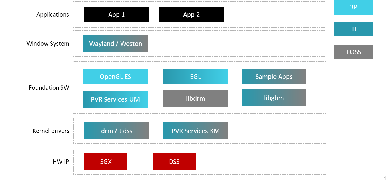
Fig. 3.4 PSDK Linux Jacinto 7 Graphics Software Stack
3.8.3. Graphics Demos
Along with the graphics driver and userspace libraries, the SDK also includes example applications. Some of the demos are based on the IMG Native_SDK examples.
Demos via Maritx
The following 3D Graphics demos are available via Matrix. The table below provides a list of these demos, with a brief description.
| Demo Name | Details |
| ChameleonMan | This demo shows a matrix skinned character in combination with bump mapping. |
| CoverFlow | This is a demonstration of a coverflow style effect |
| ExampleUI | This demo shows how to efficiently render sprites and interface elements. |
| Navigation | This is a demonstration of how to implement rendering algorithms for Navigation software. |
| Kmscube | This demo shows how to render and display multi-colored spinning cube |
Running demos in Null Window system mode
The graphics demos can also be run in null-window system mode outside of Wayland windowing system as full screen applications. In order to do so, exit Weston by pressing Ctrl-Alt-Backspace from the keyboard which connects to the EVM. Then, if the LCD screen stays in “Please wait…”, press Ctrl-Alt-F1 to go to the command line on LCD console. After that, the command line can be used from serial console, SSH console, or LCD console.
Please make sure the board is connected to at least one display before running these demos.
target # /usr/bin/SGX/demos/DRM/OGLES2Coverflow
target # /usr/bin/SGX/demos/DRM/OGLES2ChameleonMan
target # /usr/bin/SGX/demos/DRM/OGLES2ExampleUI
target # /usr/bin/SGX/demos/DRM/OGLES2Navigation
After you see the output on the display interface, hit q to terminate the application.
Some of the demos under null windowing system require the user to pass in the drm connector id. For information on how to get connector id please refer to the Display section.
3.8.4. Display
TI SoC’s are equipped with Display SubSystem (DSS) hardware to provide hardware
acceleration for alpha blending of overlays and color conversion. The DSS
hardware is exposed to the software drm API available through libdrm module.
Through this drm interface, a user space program can perform mode setting of
the display.
The drm module models the display hardware as a series of abstract hardware blocks and manages them through the API. The blocks are:
- CRTC[1]: represents a scanout engine that generates video timing signal from the data pointed to by the scanout buffer
- Connector: represents where the video timing signal is sent across to the display
- Encoder: transforms the video timing signal from CRTC to a format that is suitable for sending across the connector
- Plane: represents the overlay buffer that a CRTC can be fed with
A utility application modetest can be used to get the list of available drm
blocks. All the information available for the device can be displayed by using
it.
3.8.4.1. Finding Connector ID
Run the below modetest command:
target # modetest -M tidss -c
Look for the display device for which the connector ID is required - such as HDMI, LCD etc.
Connectors:
id      encoder status          type    size (mm)       modes   encoders
4       3       connected       HDMI-A  480x270         20      3
  modes:
        name refresh (Hz) hdisp hss hse htot vdisp vss vse vtot)
  1920x1080 60 1920 2008 2052 2200 1080 1084 1089 1125 flags: phsync, pvsync; type: preferred, driver
...
16      15      connected       unknown 0x0             1       15
  modes:
        name refresh (Hz) hdisp hss hse htot vdisp vss vse vtot)
  800x480 60 800 1010 1040 1056 480 502 515 525 flags: nhsync, nvsync; type: preferred, driver
The modes displayed are the various resolutions supported by the connected display.
3.8.4.2. Finding Plane ID
To find the Plane ID, run the modetest command:
target # modetest -M tidss -p
which should show something like below:
Planes:
id      crtc    fb      CRTC x,y        x,y     gamma size
19      0       0       0,0             0,0     0
 formats: RG16 RX12 XR12 RA12 AR12 XR15 AR15 RG24 RX24 XR24 RA24 AR24 NV12 YUYV UYVY
 props:
 ...
20      0       0       0,0             0,0     0
 formats: RG16 RX12 XR12 RA12 AR12 XR15 AR15 RG24 RX24 XR24 RA24 AR24 NV12 YUYV UYVY
 props:
 ...
3.8.5. Wayland/Weston
The supported Wayland/Weston version brings in the multiple display support in extended desktop mode and the ability to drag-and-drop windows from one display to the other.
To launch Weston, do the following:
On the target console:
target # unset WAYLAND_DISPLAY
On the default display:
target # weston --tty=1 --connector=<default connector-id>
On the secondary display:
target # weston --tty=1 --connector=<secondary connector-id>
On all connected displays (LCD and HDMI):
target # weston --tty=1
By default, the screensaver timeout is configured to 300 seconds. The user can change the screensaver timeout using a command line option:
--idle-time=<number of seconds>
For example, to set timeout of 10 minutes and Weston configured to display on all connectors, use the below command:
weston --tty=1 --idle-time=600
To disable the screen timeout and to configure Weston to display on all connectors, use the below command:
weston --tty=1 --idle-time=0
If you face any issues with the above procedure, please refer GLSDK_FAQs#Unable_to_run_Weston_on_the_GLSDK_release for troubling shooting tips.
The filesystem comes with a preconfigured weston.ini file which will be located in
/etc/weston.ini
3.8.5.1. Running Weston clients
# /usr/bin/weston-flower
# /usr/bin/weston-clickdot
# /usr/bin/weston-cliptest
# /usr/bin/weston-dnd
# /usr/bin/weston-editor
# /usr/bin/weston-eventdemo
# /usr/bin/weston-image /usr/share/weston/terminal.png
# /usr/bin/weston-resizor
# /usr/bin/weston-simple-egl
# /usr/bin/weston-simple-shm
# /usr/bin/weston-simple-touch
# /usr/bin/weston-smoke
# /usr/bin/weston-info
# /usr/bin/weston-terminal
3.8.5.2. Running multimedia with Wayland sink
The GStreamer video sink for Wayland is the waylandsink. To use this video-sink for video playback:
target # gst-launch-1.0 playbin uri=file://<path-to-file-name> video-sink=waylandsink
3.8.5.3. Exiting Weston
Terminate all Weston clients before exiting Weston. If you have invoked Weston from the serial console, exit Weston by pressing Ctrl-C.
It is also possible to invoke Weston from the native console, exit Weston by pressing Ctrl-Alt-Backspace.
3.8.5.4. Using IVI shell feature
The SDK also has support for configuring Weston ivi-shell. The default shell that is configured in the SDK is the desktop-shell.
To change the shell to ivi-shell, the user will have to add the following lines into the /etc/weston.ini.
To switch back to the desktop-shell can be done by commenting these lines in the /etc/weston.ini (comments begin with a ‘#’ at the start of line).
[core]
shell=ivi-shell.so
modules=ivi-controller.so

[ivi-shell]
ivi-input-module=ivi-input-controller.so
After the above configuration is completed, we can restart Weston by running the following commands
target# /etc/init.d/weston stop
target# /etc/init.d/weston start
Note
When Weston starts with ivi-shell, the default background is black, this is different from the desktop-shell that brings up a window with background.
With ivi-shell configured for Weston, Wayland client applications use ivi-application protocol to be managed by a central HMI window management. The wayland-ivi-extension provides ivi-controller.so to manage properties of surfaces/layers/screens and it also provides the ivi-input-controller.so to manage the input focus on a surface.
Applications must support the ivi-application protocol to be managed by the HMI central controller with an unique numeric ID.
Some important references to wayland-ivi-extension can be found at the following links:
- https://at.projects.genivi.org/wiki/display/WIE/01.+Quick+start
- https://at.projects.genivi.org/wiki/display/PROJ/Wayland+IVI+Extension+Design
3.8.5.4.1. Running Weston’s sample client applications with IVI shell
All the sample client applications in the Weston package, such as weston-simple-egl, weston-simple-shm, weston-flower, etc. also have support for ivi-shell. The SDK includes the application called layer-add-surfaces, which is part of the wayland-ivi-extension. This application allows the user to invoke the various functionalities of the ivi-shell and control the applications.
The following is an example sequence of commands and the corresponding effect on the target.
After launching Weston with the ivi-shell, please run the below sequence of commands:
target# weston-simple-shm &
At this point nothing is displayed on the screen; some additional commands are required.
target# layer-add-surfaces -l 1000 -s 2 &
This command creates a layer with ID 1000 and adds a maximum of 2 surfaces to this layer on the default screen (which is usually the LCD).
At this point, the user can see weston-simple-shm running on the LCD. This also prints the numericID (surfaceID) to which client’s surface is mapped as shown below:
layer-add-surfaces: surface (10507) created
layer-add-surfaces: surface (10507) configured with:
    dst region: x:0 y:0 w:250 h:250
    src region: x:0 y:0 w:250 h:250
    visibility: TRUE
    added to layer (1000)
layer-add-surfaces: surface (10507) configured with:
    dst region: x:0 y:0 w:250 h:250
    src region: x:0 y:0 w:250 h:250
    visibility: TRUE
    added to layer (1000)
Here, 10507 is the number to which weston-simple-shm application’s surface is mapped.
User can launch one more client application which allows layer_add_surfaces to add a second surface to the layer 1000 as shown below.
target# weston-flower &
User can control the properties of the above surfaces using LayerManagerControl as shown below to set the position/resize, opacity and visibility respectively.
target# LayerManagerControl set surface 10507 destination region 150 150 300 300
target# LayerManagerControl set surface 10507 opacity 0.5
target# LayerManagerControl set surface 10507 visibility 1
target# LayerManagerControl help
The help option prints all possible control operations with the LayerManagerControl binary. Please refer to the available options.
3.8.5.4.2. Running QT applications with IVI shell
To run the QT application with ivi-shell, set the QT_WAYLAND_SHELL_INTEGRATION environment variable to ivi-shell.
export QT\_WAYLAND\_SHELL\_INTEGRATION=ivi-shell
3.8.6. Using the PowerVR Tools
The suite of PowerVR Tools is designed to enable rapid graphics application development. It targets a range of areas including asset exporting and optimization, PC emulation, prototyping environments, on-line and off-line performance analysis tools and many more. Please refer to PowerVR-SDK for additional details on the tools and detailed documentation.
The target file system includes a subset of PowerVR tools such as PVRScope and PVRTrace recorder libraries from Imagination PowerVR SDK to profile and trace SGX activities. In addition, it also includes PVRPerfServerDeveloper tool.
3.8.6.1. PVRTune
The PVRTune utility is a real-time GPU performance analysis tool. It captures hardware timing data and counters which facilitate the identification of performance bottlenecks. PVRPerfServerDeveloper should be used along with the PVRTune running on the PC to gather data on the SGX loading and activity threads. You can invoke the tool with the below command:
target # /opt/img-powervr-sdk/PVRHub/PVRPerfServer/PVRPerfServerDeveloper
3.8.6.2. PVRTrace
The PVRTrace is an OpenGL® ES API recording and analysis utility. PVRTrace GUI provides off-line tools to inspect captured data, identify redundant calls, highlight costly shaders and many more. The default filesystem contains helper scripts to obtain the PVRTrace of the graphics application. This trace can then be played back on the PC using the PVRTrace Utility.
To start tracing, use the below commands as reference:
target # cp /opt/img-powervr-sdk/PVRHub/Scripts/start_tracing.sh ~/.
target # ./start_tracing.sh <log-filename> <application-to-be-traced>
Example:
target # ./start_tracing.sh westonapp weston-simple-egl
The above command will do the following:
- Setup the required environment for the tracing
- Create a directory under the current working directory called pvrtrace
- Launch the application specified by the user
- Start tracing the PVR Interactions while recording the traces to a file under the current directory
To end the tracing, the user can invoke the Ctrl-C and the trace file path will be displayed.
The trace file can then be transferred to a PC, and we can visualize the application using the host side PVRTrace utility. Please refer PowerVR-SDK for more details.
| [1] | CRTC stands for cathode-ray tube controller, a throw back to the old cathode-ray tubes TV’s which had a controller that generated video timings based on the data it is being fed by a buffer. |