4.2. HSR_PRP
4.2.1. Protocol Overview
HSR (High-availability Seamless Redundancy) and PRP (Parellel Redundancy Protocol) are protocols supporting redundant network connections defined by IEC 62439-3. Both operate by using two ethernet ports together, and duplicating every frame to be sent over both ports, so if one connection fails, the transmission succeeds. Frames are tagged with a sequence number, so the receiving node can identify and discard duplicates. HSR/PRP provides an advantage over other protocols that handle link failure (e.g. STP/RSTP) because there is no downtime or packet loss on link failure. This is required in some industrial networking situations.
The major difference between HSR and PRP is that HSR networks are configured as a ring, then frames are sent both directions around the ring by all nodes. PRP networks can take any configuration, and all connections are simply physically duplicated. Additionally, PRP nodes can interoperate with standard ethernet networks, while HSR cannot. (See more details below and full details in IEC 62439-3)
The HSR/PRP protocols can be run by the Linux kernel, and function over standard ethernet ports, but the advantage of using the PRU-ICSS supported industrial ethernet ports is that the PRU-ICSS HSR/PRP firmware offloads much of the protocol functionality to firmware, allowing more processing bandwidth for an application, and in the case of HSR, providing faster cut-through switching as frames pass through ring nodes.
4.2.2. Getting Started
To try out HSR/PRP (assuming two supported platforms are set up already, and PRU-ICSS ports are eth1/eth2):
1 ) Connect the PRU-ICSS ports between devices, eth1 to eth1 and eth2 to eth2. (This acts as a 2 node ring for HSR, or a 2 node point-to-point for PRP)
2 ) Configure ports to have the same MAC address
ifconfig eth1 0.0.0.0 down && ifconfig eth2 0.0.0.0 down
ifconfig eth1 hw ether 70:FF:76:1C:0E:8C && ifconfig eth2 hw ether 70:FF:76:1C:0E:8C
3 ) Configure offload feature, and create HSR/PRP interface
(for HSR)
ethtool -K eth1 hsr-rx-offload on && ethtool -K eth2 hsr-rx-offload on
ifconfig eth1 up && ifconfig eth2 up
ip link add name hsr0 type hsr slave1 eth1 slave2 eth2 supervision 45 version 1
ifconfig hsr0 192.168.2.20
(for PRP)
ethtool -K eth1 prp-rx-offload on && ethtool -K eth2 prp-rx-offload on
ifconfig eth1 up && ifconfig eth2 up
ip link add name prp0 type hsr slave1 eth1 slave2 eth2 supervision 45 proto 1
ifconfig prp0 192.168.2.20
4 ) Attempt to ping from one device to the other, and try disconnecting a link. The connection will continue without loss.
4.2.3. ICSS Firmware
A common firmware is used across TI RTOS and Linux implementations of HSR/PRP. This section describes the firmware details.
4.2.3.1. Firmware Features Supported
HSR/PRP
The implementation is as per IEC 62439-3 Ed 2.0
Operates as a DAN (Dual Attached Node)
HSR
Operates as a DANH
As per clause 5 of the standard
Support for modes – H, T, U and N as per standard
Modes can be changed at run time
PRP
Operates as a DANP
As per clause 6 of the standard
Two ports as per standard, Port A and Port B
Support for Node Table
Total 128 entries on AMICx, AM335x, AM437x
Total 256 entries on AM57xx & K2G
Hash Table for faster lookup
O(1) complexity
Node Table statistics
Support for Multicast Filtering
Supported on all SoCs
Hash Table for faster lookup
O(1) complexity
Duplicate Discard Table
Duplicate discard on Port to Host path (HSR and PRP)
Duplicate discard table on Port to Port path (HSR)
Data integrity (CRC) check during port to port forwarding, except cut through (HSR)
QoS scheme : 3-bit VLAN PCP
No of levels supported : 8
Number of host queues : 2 | 4 QoS levels per host queue
Number of port queues : 4 | 2 QoS levels per port queue
Number of host queues are configurable
Statistics
Supports all MIB statistics as per standard
Node Table statistics for debugging
PTP/1588
PTP Slave and Master mode
Supports P2P clock.
PTP over 802.3 (Annex F)
Transparent Clock supported
Ordinary Clock supported
Single and Two step clock supported
Peer delay Response is always sent as two-step
Storm Prevention : Yes. Configurable per port
4.2.3.2. Duplicate algorithm and table
Handling duplicate frames is one of the main tasks in HSR and PRP. The LRE must not provide the duplicate of a frame to its upper layer in order to offload the processor. The algorithm for discarding duplicates is not specified in IEC 62439-3. However, the standard mandates that the algorithm must be designed such that it never rejects a legitimate frame, while occasional acceptance of a duplicate can be tolerated.
In HSR, additionally to discarding duplicates destined to the host, a discard operation should also be used to prevent frames from looping in the network. A looping frame is a frame that is never discarded in any node of the network and therefore it keeps looping indefinitely. Normally, such a frame should be dropped by its source node. The function handles the case when a defective HSR device does not filter correctly according to source/destination address. This operation is less critical than the host duplicate discard. It is also specified that any duplicate discard method shall be able to forget an entry identified by the source MAC address and the sequence number after a time EntryForgetTime (default 400ms).
A table holds entries representing frames that have been registered in the LRE, each entry is represented bya frame signature. The signature consists of the source MAC address and the 16 bit sequence number. The sequence number value is incremented by 1 when a frame and its duplicate are sent by a source in an HSR network. This signature allows identifying a frame uniquely. When a frame is received, the list is searched by comparing the frame signature with all entries in the table. If such an entry is found, the frame is a duplicate and shall be discarded. If no entry exists, the frame is the first one received and needs to be forwarded to the application and/or – in case of HSR - to the other port. With a successful forwarding process (frame received with no error), a new entry with the signature of that frame is created in the table.
A linear lookup process is too time consuming; thus Hash algorithms are used to decrease the search time.
4.2.3.3. Port to Host Duplicate Table
It is used to prevent sending duplicate frames to the upper layers. This table is common for both PRUs. Resource sharing implies that collision (two PRUs accessing the same data) must be handled. Since the table is common to both PRUs, the host duplicate rejection must be done after the EOF is detected in order to avoid rejecting legitimate frames.
4.2.3.4. Port to Port Duplicate Table
A PRU forwards the frames received from one HSR port to the other HSR port, unless the frame was sent already. Each PRU has its own port duplicate table. A search operation can start before the EOF is detected since the table is not shared between the PRU and is not subject to any modification during the reception of a frame. In order to minimize the load of the PRU after EOF reception, the search operation in the port duplicate table is executed during frame reception. Moreover, this allows to quickly detecting if the frame should be discarded early in the reception process. An insertion in the table is still made only after the EOF is detected, but the operation is much faster since the result of the search operation can used.
4.2.3.5. Node Table
The node table is a central element of the HSR/PRP mechanism although the standard declares node tables optional. This firmware implements node tables for HSR and PRP. Node table handling is implemented in the PRU and comprises of registering incoming supervision and non-supervision-frames as well as ageing and deleting of old entries. The standard requires updating the node table when a supervision frame is received. Accessing the node table is thus not critical since supervision frames are sent only every 2 seconds. For HSR, to maintain statistics for each source node of the network and to facilitate debugging, the implementation updates the node table for each frame received by the host from a source that has previously sent a supervision frame. A further advantage of this approach is having a similar implementation for HSR and PRP. Indeed, the PRP Standard requires updating the node table, if implemented, for all the incoming frames in order to keep track of the traffic contented to each redundant LAN. The node table is accessible by the host for management purposes. Update- and register operations in the table should be done when the frame is completely received in order to avoid registering erroneous frames.
The node table search/update operation is very critical since it is resource/time consuming (maximum NODE_TABLE_SIZE is 256 entries). In the worst case scenario (node table full), a linear lookup operation in the receiving task could load the PRU too much and in consequence could cause Rx overflow or TX underflow. Moreover the node table is common to both PRUs and since it is accessed often, the resource-sharing management has additional impact on the latency. Optimized linear tables were considered, but the timing remained too critical in the worst case scenario. Hash tables are not considered because it is not allowed to lose entries due to collisions. The implemented solution is a sorted table with a two layer table structure. This allows to significantly optimize the lookup time especially when the table has lots of valid entries.
It is important to notice that in a normal HSR case scenario there are - in average - significantly more successful lookup operations (MAC address found in the table) than insertion and deletion operations. Indeed, insertion operations are only made with a supervision frame. This assumption cannot be made for PRP since all frames can create an entry in the node table. The design is therefore optimized according to this assumption.
4.2.3.6. Frame duplication from the host
Frames sent by the host must be duplicated and should be sent to both ports nearly at the same time for HSR and PRP. In a simple approach, the host stores the frame in the queue of one PRU, the PRU then waits until both ports are available and finally sends the frame at the same time via both ports. However, this solution is not resource efficient and it increases the latency of one PRU when waiting for the PORT to be ready. Therefore, a solution that off-loads the PRU from the duplication task is implemented: the host driver duplicates the frames and puts a copy to each PRU queue.
The implementation is however not straightforward:
Since the frames are not “linked” to each other, there is no guarantee that the frames are sent by both PRUs within a short interval. The host could control the queue status and only push the frames in the highest priority queue of both PRU when the queues are free. This would force each PRU to send the frame and its duplicate next. Nevertheless, for HSR this solution removes the prioritization of the frame circulating in the HSR ring as a PRU could buffer a high priority frame from the ring due to a lower priority frame sent by the host. Frames circulating in the ring are to be treated with higher priority than frames sent by the host. There is a compromise to be found.
The solution is the following: The host driver duplicates the frame and puts the duplicates in the queues of each PRU. The queue is selected based on the priority of the frame. Each PRU handles the frame independently and we only have the assurance that each frame will be sent out within an unknown interval. The drawback of this solution is the lack of control on when each frame will be sent out. The interval can be bigger than one maximum sized Ethernet frame in this case.
4.2.3.7. Supervision Frame
Incoming supervision frames are received and processed by the PRU. On reception of a frame, the PRU updates the node table and the statistic counters. For HSR, if the received supervision frame originates from the receiver (i.e. it traversed the whole ring) it is discarded. Otherwise it is sent to the next node in store and forward mode. The reason for using store and forward mode is the following: A supervision frame might trigger the creation of an entry in the node table and this task is time consuming. By sending the frame in store and forward mode, more time is available for this operation while receiving the frame. Each device in an HSR/PRP network sends supervision frames at a constant time interval. Outgoing supervision frames are composed and sent by the host CPU.
4.2.3.8. Cut-Through for HSR
Cut through happens when switch firmware bypasses the transmit queues and directly copies data from Rx FIFO to Tx FIFO. The concept is explained here
The concept of forwarding frames from HSR port to HSR port when operating in cut-through mode deserves more explanation since the following boundary conditions require a carefully balanced implementation: •Cut-through of a frame shall start as early as possible in order to minimize the propagation delay in each node. The ICSS switch supports starting the cut-through operation after a configurable amount of bytes received. Theoretically, for HSR the minimum number of bytes required is 22 (12 bytes Source-/Destination MAC, 4 bytes VLAN Tag, 6 bytes HSR Tag) in order to have all the necessary data to take the routing decision. The receiving process is optimized to allow cut through as soon as possible depending on the type of the frame ( see start receiving process in 3.2.2 Micro Scheduler). •Duplicates shall not be cut through (i.e. the detection of a duplicate shall be finished before the next node in the ring starts processing the frame) •Detection of duplicates (computing the hash index and scanning a bin in the hash table) is time consuming
Waiting for the duplicate detection before taking the cut through decision would delay the frame too much. Starting to cut-through a frame without port duplicate rejection minimizes the delay and allows starting the receiving process after 14 bytes. Once the cut through of a frame has started, the port duplication rejection process starts. If the frame is identified as duplicate or corrupted, the transmission of the frame is aborted by asserting the TX_RESET which will reset the transmit FIFO and clear all its contents and therefore corrupt the frame being cut-though.
4.2.3.9. HSR/PRP Memory Map
Name of Offset |
Description Refer to hsr_prp_firmwar e.h |
Offset in Shared RAM |
Size (in bytes) |
|---|---|---|---|
INDEX_ARRAY |
Index entry for Node Table |
0x1E0 |
144 |
NODE_TABLE |
Node Table for the DANH/DANP |
0x1FCO |
4132 |
Table: Shared RAM Memory Map
Name of Offset |
Description Refer to hsr_prp_firmware.h |
Offset in Shared RAM (base : 0x140) |
|---|---|---|
LRE_CNT_TX_A |
Number of frames successfully sent over port A that are HSR/PRP tagged |
4 |
LRE_CNT_TX_B |
Same for Port B |
8 |
LRE_CNT_TX_C |
Number of frames successfully sent to Host that are HSR/PRP tagged |
12 |
LRE_CNT_ERRWRONGLAN_A |
number of frames with the wrong LAN identifier received on LRE port A |
16 |
LRE_CNT_ERRWRONGLAN_B |
Same for Port B |
20 |
LRE_CNT_ERRWRONGLAN_C |
Same for Host |
24 |
LRE_CNT_RX_A |
number of frames received successfully with HSR or PRP TAG on a LRE port A |
28 |
LRE_CNT_RX_B |
Same for Port B |
32 |
LRE_CNT_RX_C |
Same for Host |
36 |
LRE_CNT_ERRORS_A |
number of frames with errors received on this LRE port A |
40 |
LRE_CNT_ERRORS_B |
Same for Port B |
44 |
LRE_CNT_ERRORS_C |
Same for Host |
48 |
LRE_CNT_NODES |
Number of active nodes in the node table |
52 |
LRE_CNT_PROXY_NODES |
Number of active proxy nodes in the node table |
56 |
LRE_CNT_UNIQUE_RX_A |
Number of entries in the duplicate detection mechanism on port A for which no duplicate was received |
60 |
LRE_CNT_UNIQUE_RX_B |
Same for Port B |
64 |
LRE_CNT_UNIQUE_RX_C |
Same for Host |
68 |
LRE_CNT_DUPLICATE_RX_A |
Number of entries in the duplicate detection mechanism on port A for which one single duplicate was received |
72 |
LRE_CNT_DUPLICATE_RX_B |
Same for Port B |
76 |
LRE_CNT_DUPLICATE_RX_C |
Same for Host |
80 |
LRE_CNT_MULTIPLE_RX_ A |
Number of entries in the duplicate detection mechanism on port A for which more than one duplicate was received |
84 |
LRE_CNT_MULTIPLE_RX_ B |
Same for Port B |
88 |
LRE_CNT_MULTIPLE_RX_ C |
Same for Port C |
92 |
LRE_CNT_OWN_RX_A |
Number of entries on port A received from device itself |
96 |
LRE_CNT_OWN_RX_B |
Same for Port B |
100 |
LRE_DUPLICATE_DISCARD |
Number of frame retreive by the host |
104 |
LRE_TRANSPARENT_RECEPT ION |
Number of frame received without PRP RCT |
108 |
LRE_NODE_TABLE_LOOKUP _ERROR_A |
Number of instances where node table look up failed for Port A |
112 |
LRE_NODE_TABLE_LOOKUP _ERROR_B |
Same for Port B |
116 |
LRE_NODE_TABLE_FULL |
If Node Table is full, this value is incremented |
120 |
LRE_MULTICAST_DROPPED |
If the Multicast frame is dropped because of no hash value configured in the filter table, this value is incremented |
124 |
LRE_VLAN_DROPPED |
If the frame is dropped because of no entry for the VID of the frame in the VLAN filter table, this value is incremented |
128 |
Table: LRE Interface Stats
Name of Offset |
Description Refer to hsr_prp_firmwar e.h |
Offset in PRU0 DRAM |
Size (in bytes) |
|---|---|---|---|
DUPLICATE_HOST_T ABLE |
Duplicate detection table for Host |
0x200 |
6136 |
NEXT_FREE_ADDRES S_NT_QUEUE |
Offset of the queue of the free address for the node table |
0x1B00 |
132 |
POINTERS_FREE_AD DR_NODETABLE |
Offset of the read and write pointer of the free address of the node table(read.w0,writ e.w2) |
0x1B84 |
4 |
Table: PRU0 RAM Memory Map
Name of Offset |
Description Refer to hsr_prp_firmwar e.h |
Offset in PRU1 DRAM |
Size (in bytes) |
|---|---|---|---|
DUPLICATE_PORT_T ABLE_PRU0 |
Offset of port duplicate table for PRU0 (HSR Only) |
0x200 |
3064 |
DUPLICATE_PORT_T ABLE_PRU1 |
Offset of port duplicate table for PRU1 (HSR Only) |
0xE00 |
3064 |
NODE_TABLE_SIZE |
Size of the node table [0..128] |
0x1C00 |
4 |
NODE_TABLE_ARBIT RATION |
Busy slave flag and busy master flag for 3 lock used to protect the node table |
0x1C04 |
4 |
DUPLICATE_HOST_T ABLE_SIZE |
Size and setup (N and M) of duplicate host table |
0x1C08 |
4 |
DUPLICATE_PORT_T ABLE_SIZE |
Size and setup (N and M) of duplicate port table |
0x1C1C |
4 |
NODE_FORGET_TIME |
Time after which a node entry is cleared (10ms resolution) |
0x1C20 |
4 |
DUPLI_FORGET_TIM E |
Time after which an entry is removed from the duplicate table (10ms resolution) |
0x1C24 |
4 |
PATH_BROKEN_NB_ FRAM_DIFF |
Supervision frame Counter minimum difference to detect a broken path |
0x1C28 |
4 |
DUPLI_PORT_CHECK _RESO |
Time interval to check the port duplicate table |
0x1C2C |
4 |
DUPLI_HOST_CHECK _RESO |
Time interval to check the host duplicate table |
0x1C30 |
4 |
NODETABLE_CHECK_ RESO |
Time interval to check the node duplicate table |
0x1C34 |
4 |
HOST_TIMER_CHECK _FLAGS |
Host | Port |
0x1C38 |
4 |
HOST_DUPLICATE_A RBITRATION |
Arbitration flag for the host duplicate task |
0x1C3C |
4 |
ICSS_FIRMWARE_RE LEASE |
Time counter to trigger the host duplicate table check task |
0x1C40 |
4 |
RED_FIRMWARE_REL EASE |
Time counter to trigger the Node Table check task in firmware |
0x1C44 |
4 |
SUP_ADDR |
Supervision address in HSR |
0x1C48 |
4 |
Table: PRU1 RAM Memory Map
4.2.4. Linux Software
4.2.4.1. Overview
In both HSR and PRP protocols, the DAN (Dual Attached Node) sends an identical frame to both the interfaces and uses a sequence number in the tag to allow drop duplicates at the Rx node to achieve redundancy. This section describes the different software components of a Linux based HSR/PRP solution to support redundancy.
4.2.4.2. Features supported
HSR/PRP
100 Mbits/s Full Duplex Ethernet Interface
The implementation is as per IEC 62439-3 Ed 2.0
Operates as a DAN (Dual Attached Node)
HSR
Operates as a DANH
As per clause 5 of the standard
Support for modes – H, T, U and N as per standard
Modes can be changed at run time
Cut-through switching
PRP
Operates as a DANP
As per clause 6 of the standard
Two ports as per standard, Port A and Port B
Support for Node Table
Total 128 entries on AMICx, AM335x, AM437x
Total 256 entries on AM57xx
Hash Table for faster lookup
Node Table statistics
Support for Multicast Filtering
Supported on all SoCs
Hash Table of 256 entries for faster lookup
O(1) complexity
User configurable mask to select bits for hashing
Support for VLAN over HSR/PRP interface
Support for VLAN Filtering
VLAN filter table of 4096 entries for perfect match
O(1) complexity
Duplicate Discard Table
Duplicate discard on Port to Host path (HSR and PRP)
Duplicate discard table on Port to Port path (HSR)
Data integrity (CRC) check during port to port forwarding, except cut through (HSR)
QoS scheme : 3-bit VLAN PCP
No of levels supported : 2
Number of host queues : 2 | 2 QoS levels per host queue
Number of port queues : 2 | 2 QoS levels per port queue
Statistics
Supports all MIB statistics as per standard
Node Table statistics for debugging
Storm Prevention : Yes. Configurable per port
Dual instance of HSR/PRP using two PRU-ICSS on AM571x
VLAN tag support in Supervision frames
Run time change of Protocol at PRU-ICSS without reboot
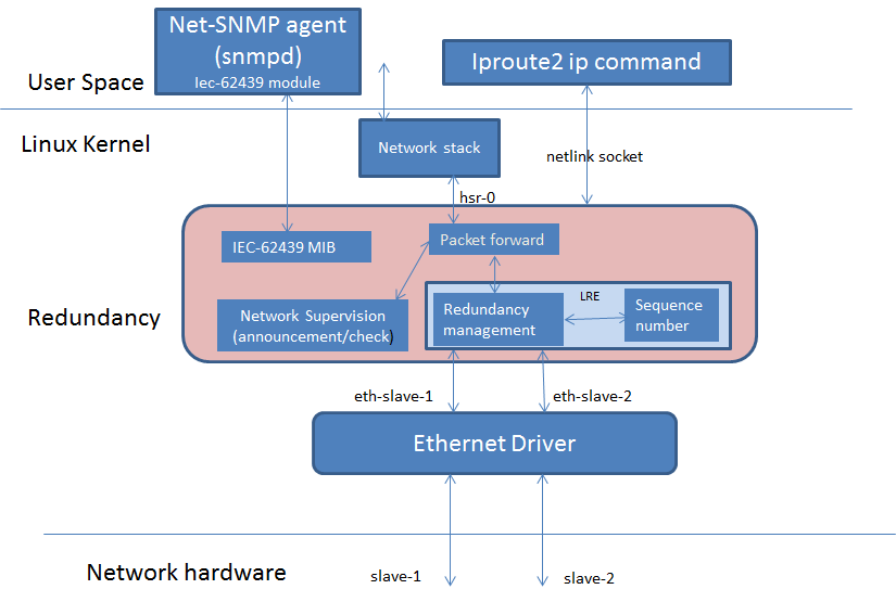
4.2.4.3. Software Architecture
The diagram below highlights the software components that are modified or developed specifically for HSR/PRP. These along with other standard Linux OS components are used to implement the Linux HSR/PRP DAN (Dual Attached Node).
Linux Kernel drivers
HSR/PRP driver
Ethernet driver
User space
Net-SNMP
iproute2
4.2.4.3.1. HSR/PRP Driver source code and Kconfig option
The driver source code is located under net/hsr-prp folder of the Linux source tree. To build kernel with this driver, set Kconfig option CONFIG_HSR=y in the dotconfig or enable it from the menu.
4.2.4.3.2. Linux HSR/PRP Driver
The Linux networking subsystem in upstream kernel has added support for HSR driver starting in v3.12 (HSRv0 - IEC 62439-3:2010) and enhanced the same to support HSRv1 (IEC 62439-3:2012) in v4.6. This driver allows user to create an HSR network device with a pair of slave network interfaces (A and B) that are standard Ethernet interfaces. For example on TI’s AM572x IDK EVM, there are two Ethernet interfaces (10/100) per each PRU ICSS. The PRU Emac driver available for ICSS PRU Ethernet h/w supports two Ethernet ports. Using ip link command, user will be able to setup a HSR interface on this EVM that pair the two PRU Ethernet interfaces to create a HSR node or DAN-H.
TI has enhanced the Linux HSR driver and ip link command in iproute2 package to support PRP defined in IEC 62439-3 clause 4. With this change, user will be able to create a Doubly Attached Node with PRP (DAN-P) using standard Ethernet interfaces. As in the case of HSR, using ip link command, user will be able to setup a prp interface using two Ethernet interfaces such as the one provided by PRU Dual EMAC driver.
Linux HSR/PRP driver provides a standard Ethernet interface to application layer and hide the details of the redundancy protocol under the driver layer. Linux HSR/PRP driver implements the Link Redundancy Entity (LRE) that is central to implementing redundancy using respective protocol.
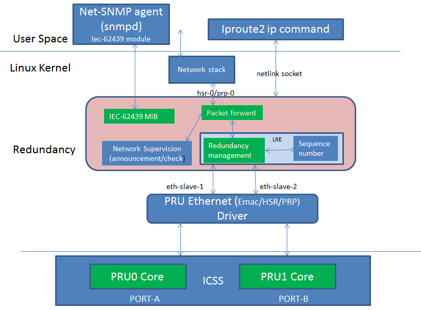
HSR LRE functions and L2 routing can be offloaded to the firmware running on the PRU cores of ICSS. The diagram below shows the architecture of an Offloaded HSR/PRP driver. The upper layer driver is existing Linux HSR/PRP driver described in the previous section. The PRU Ethernet driver exports HSR/PRP capabilities in the NetDev feature flags. The green blocks in the Redundancy layer shows the software blocks that gets offloaded to PRUs in ICSS which is shown green as well. The upper layer HSR/PRP driver uses the feature flags exported by the PRU Ethernet driver to disable corresponding functions in its layer. The firmware is a re-use from the TI RTOS implementation that is discussed above. Re-use means the data structures and API should be re-used across both TI RTOS and Linux driver implementations. A common PRU Ethernet driver is developed to support existing Dual EMAC device as well HSR/PRP
4.2.4.3.3. PRU-ICSS Subsystem Driver
PRU-ICSS Subsystem Driver provide a set of functions to client driver such as PRU Ethernet (described in next section) to load and run firmware on a specific core, such as PRU on a PRU-ICSS. On a SoC, there can be 1 or 2 instance of the PRU-ICSS and client driver might want to know which instance it is referring to. PRU-ICSS sysfs files are specific to an instance and user might have to know what instance the file refers to. Following mapping is used for the ID based on the SoC and the PRU-ICSS instance.
SoC |
ID |
if number |
ICSS TRM reference |
|---|---|---|---|
AM3 |
0 |
eth0/1 |
PRU-ICSS |
AM4 |
0 |
eth1/2 |
PRU-ICSS0 |
AM571 |
1 |
eth2/3 |
PRU-ICSS1 |
AM571 |
2 |
eth4/5 |
PRU-ICSS2 |
AM572/4 |
2 |
eth2/3 |
PRU-ICSS2 |
In the following section, the PRU-ICSS ID is used in the sysfs file path and the same can be obtained from the table above to know which PRU-ICSS the file refers to.
You can also check which PRU-ICSS an ethernet interface belongs to via command line, e.g. eth2 on different platforms:
AM571x:
root@am57xx-evm:~# ls -l /sys/class/net/eth2 | grep device
lrwxrwxrwx    1 root     root             0 Jun 10 11:29 device -> ../../../pruss1_eth
AM572x:
root@am57xx-evm:~# ls -l /sys/class/net/eth2 | grep device
lrwxrwxrwx    1 root     root             0 Jun 10 11:29 device -> ../../../pruss2_eth
4.2.4.3.4. PRU Ethernet Driver (Dual EMAC/HSR/PRP)
As of Processor SDK 7.x, the PRU Ethernet driver supports HSR/PRP/SWITCH firmware offload. The PRU Ethernet driver initially probe in Dual EMAC mode and loads Dual EMAC firmware. HSR/PRP/SWITCH are the firmware offload cases. Please refer to RSTP section on PRUETH SWITCH driver. When a HSR/PRP firmware is loaded, the PRU Ethernet driver will do proper firmware configurations and notify the Linux HSR/PRP driver (under net/hsr directory. Also referred to as upper driver) stack that offload has been enabled through netdev feature flags. From then on, LRE functionality at the rx side is disabled in Linux HSR/PRP upper driver and carried out in firmware. Tx LRE function continues to be in Linux HSR/PRP driver. i.e Tx frame duplication and Supervision frame generation is still done in the upper driver.
Notice that, from the user point of view, all of the above mentioned driver behavior is transparent to the user.
Note
For all discussion and examples shown, AM57xx device is used as example, but different devices will use different ports. Please see PRU-ICSS Subsystem Driver for interface number and PRU-ICSS ID information for different SoCs.
As of Processor SDK 5.1.x, the driver supports 2 instances of HSR/PRP one on each of PRU-ICSS on AM5xxx as per table below.
PRU-ICSS1
PRU-ICSS2
HSR
HSR
HSR
PRP
PRP
PRP
PRP
HSR
4.2.4.3.4.1. Queue Usage and VLAN PCP to Queue Map
At the Ingress, there are two queues available for queueing the frames coming from each port or PRU to Host and two queues available for packets from Host to each PRU. At the Egress, there are additionally two more queues used for forward traffic from PRU1 to PRU0 and vice-versa. PRUETH driver configures the PCP to Queue MAP in Shared RAM which is used by firmware to decide which queue to pick to enqueue frames towards Host or other PRU. Priority queues are assigned based on the PCP value in VLAN tag of an Ethernet frame. Untagged frame is treated like PCP 0. Here is the mapping value configured by driver in 4 bytes starting at offset QUEUE_2_PCP_MAP_OFFSET (defined in icss_lre_firmware.h). Same mapping is used for Ingress and Egress traffic.
The convention is that higher queue value corresponds to lower priority
For HSR/PRP Ethernet types
At ingress to Host
byte 0 - To host from PRU 1, PCP 0-3 => Q3
byte 1 - To host from PRU 1, PCP 4-7 => Q2
byte 2 - To host from PRU 0, PCP 0-3 => Q1
byte 3 - To host from PRU 0, PCP 4-7 => Q0
At the ingress, firmware inspect the PCP value in the incoming Ethernet frame’s VLAN tag and choose a priority queue to enqueue the frame based on the above mapping.
At egress from host to wire/network
PRU0/PRU1
---------
byte 0 - from Host to PRU, PCP 0-3 => Q3
byte 1 - from Host to PRU, PCP 4-7 => Q2

PRU0
-----
byte 2 - from PRU1 to PRU0, PCP 0-3 => Q1
byte 3 - from PRU1 to PRU0, PCP 4-7 => Q0

PRU1
-----
byte 2 - from PRU0 to PRU1, PCP 0-3 => Q1
byte 3 - from PRU0 to PRU1, PCP 4-7 => Q0
Driver choose the priority queue for egress transmission based on the PCP value of the Ethernet frame received from the upper layer. Firmware sends the frames first from Q0 and Q2 in a round robin fashion. Once these queues are drained, it then sends from the next higher queues Q1 and Q3 again in a round robin fashion. At the egress, Q0/Q1 are port queues and Q2/Q3 are host queues.
For Dual EMAC Ethernet type
In Dual EMAC case, mapping is hard coded in firmware.
At ingress to Host
From PRU0 to Host, PCP 0-3 => Q1
From PRU0 to Host, PCP 4-7 => Q0

From PRU1 to Host, PCP 0-3 => Q3
From PRU1 to Host, PCP 4-7 => Q2
At egress from host to wire/network
PRU0/PRU1
-- ---------
From Host to PRU0/PRU1, PCP 0-1 => Q3
From Host to PRU0/PRU1, PCP 2-3 => Q2
From Host to PRU0/PRU1, PCP 4-5 => Q1
From Host to PRU0/PRU1, PCP 6-7 => Q0
Firmware sends the frames first from Q1, and then from the next higher queue (Q2) and so forth.
For Dual EMAC and SWITCH ethernet types, at the Ingress, two separate irq handlers are assigned to each port to process the packets. Driver uses NAPI and NAPI polling is kicked once the interrupt event is received by for each port. Packets are drained by the NAPI Poll function.
For HSR/PRP Ethernet type, an interrupt is attached to a pair of High Priority Queues and another interrupt to the pair of low priority queues. each queue is associated with a port. Two NAPI instances used, one for high priority queues and another for low priority queues to independently scan and drain the queues from the two ports. Interrupt handler kicks NAPI. NAPI poll handler drains packets from the High priority or Low priority queues based on timestamp maintained in memory. i.e packets are ordered based on the timestamp.
4.2.4.3.4.2. Changing protocol at PRU Ethernet
PRU Ethernet driver supports multiple protocols/Ethernet types based on the firmware loaded on ICSS PRU. By default, the PRU Ethernet driver is probed to be in the Dual EMAC mode and EMAC firmware is loaded on to the PRU. From this mode, user will be able to change to one of the Ethernet type without having to reboot the board:-
HSR
PRP
Two feature flags are added to help offload HSR or PRP in the PRU Ethernet driver :- hsr-rx-offload and prp-rx-offload. PRU Firmware essentially offload the rx side processing of LRE, such as duplicate detection and drop, node table update, stats update etc. To reflect the same, the features are named with a rx-offload suffx to the protocol name. Ethtool command has an option -K to set or clear the feature in a network device. So this flag can be set or reset rx offload feature in the PRU Ethernet device. As the device may be hooked up to a upper HSR/PRP network device, user is expected to delete the hsr or prp interface before changing the flag at the PRU Ethernet device. General procedure to change protocol at PRU Ethernet device is as follows:-
Below assumes that hsr or prp interface using the PRU Ethernet devices is currently deleted. Here are the steps at a high level:-
1. Bring down the two PRU Ethernet interfaces using ifconfig and unassign the ip address using ifconfig. For example
ifconfig eth2 down 0.0.0.0
ifconfig eth3 down 0.0.0.0
2. If the PRU Ethernet device is currently running HSR or PRP offload feature, the same has to be disabled before switching to Dual EMAC or another protocol using ethtool -K option. For example if HSR is currently running, do
ethtool -K eth2 hsr-rx-offload off
ethtool -K eth3 hsr-rx-offload off
Similarly if PRP is currently running, do
ethtool -K eth2 prp-rx-offload off
ethtool -K eth3 prp-rx-offload off
3. If user would like to offload HSR, enable the feature hsr-rx-offload on both devices.
ethtool -K eth2 hsr-rx-offload on
ethtool -K eth3 hsr-rx-offload on
4. Now the PRU Ethernet devices can be paired to create an HSR interface using ip link command. To offload PRP user does following command in step 3
ethtool -K eth2 prp-rx-offload on
ethtool -K eth3 prp-rx-offload on
To display the offload feature currently active at the PRU Ethernet, user may type following command for example for eth2
ethtool -k eth2
Sample commands
Before using these commands, save the MAC address of both interfaces. These sample commands assumes a MAC address of 70:FF:76:1C:0E:8C for both PRU Ethernet interfaces and an IP address of 192.168.2.20 for the hsr/prp interface. Eth3 MAC address is assumed to be 70:FF:76:1C:0E:8E. Also assumes user create hsr0 or prp0 interface using eth2 and eth3 interfaces. Please note that for each DAN, user needs to assign unique MAC address and IP address from the same subnet.
To switch from Dual EMAC to HSR
ifconfig eth2 0.0.0.0 down
ifconfig eth3 0.0.0.0 down
ifconfig eth2 hw ether 70:FF:76:1C:0E:8C
ifconfig eth3 hw ether 70:FF:76:1C:0E:8C
ethtool -K eth2 hsr-rx-offload on
ethtool -K eth3 hsr-rx-offload on
ifconfig eth2 up
ifconfig eth3 up
ip link add name hsr0 type hsr slave1 eth2 slave2 eth3 supervision 45 version 1
ifconfig hsr0 192.168.2.20
To switch from HSR to PRP
ip link delete hsr0
ifconfig eth2 down
ifconfig eth3 down
ethtool -K eth2 hsr-rx-offload off
ethtool -K eth3 hsr-rx-offload off
ethtool -K eth2 prp-rx-offload on
ethtool -K eth3 prp-rx-offload on
ifconfig eth2 up
ifconfig eth3 up
ip link add name prp0 type hsr slave1 eth2 slave2 eth3 supervision 45 proto 1
ifconfig prp0 192.168.2.20
To switch from PRP to HSR
ip link delete prp0
ifconfig eth2 down
ifconfig eth3 down
ethtool -K eth2 prp-rx-offload off
ethtool -K eth3 prp-rx-offload off
ethtool -K eth2 hsr-rx-offload on
ethtool -K eth3 hsr-rx-offload on
ifconfig eth2 up
ifconfig eth3 up
ip link add name hsr0 type hsr slave1 eth2 slave2 eth3 supervision 45 version 1
ifconfig hsr0 192.168.2.20
To switch from HSR to Dual EMAC
ip link delete hsr0
ifconfig eth2 down
ifconfig eth3 down
#Restore eth3 MAC address
ifconfig eth3 hw ether 70:FF:76:1C:0E:8E
ethtool -K eth2 hsr-rx-offload off
ethtool -K eth3 hsr-rx-offload off
ifconfig eth2 192.168.2.20
ifconfig eth3 192.168.3.20
To switch from PRP to Dual EMAC
ip link delete prp0
ifconfig eth2 down
ifconfig eth3 down
ethtool -K eth2 prp-rx-offload off
ethtool -K eth3 prp-rx-offload off
#Restore eth3 MAC address
ifconfig eth3 hw ether 70:FF:76:1C:0E:8E
ifconfig eth2 192.168.2.20
ifconfig eth3 192.168.3.20
4.2.4.4. Multicast filtering
Multicast filtering is an Ethernet frame filtering feature in PRU firmware based on the destination MAC address of the received frame. The PRU provides a Multicast filter table in Data RAM1 of PRU with a size of 256 entries of 1 byte each. Firmware implements an imperfect match for filtering the frames based on a hash calculated using the destination MAC address of the frame if the destination address is a multicast MAC address.
Hash = (MAC_ADDR[0] XOR
        MAC_ADDR[1] XOR
        MAC_ADDR[2] XOR
        MAC_ADDR[3] XOR
        MAC_ADDR[4] XOR
        MAC_ADDR[5])
Where MAC_ADDR is the multicast MAC address which is extracted from the destination address of the Ethernet frame. A bitwise XOR operation is performed on each byte of MAC address to get the hash value. The hash is used to index into the Multicast filter table to check if it is set (1) or reset (0). If set, the frame is forwarded to ARM core (a.k.a Host). If reset, the frame is dropped at the PRU. This is an imperfect match since there can be multiple MAC addresses that produces the same hash value. So these frames will get forwarded to the ARM core.
Typically, an application joins the multicast group either using a raw socket of type SOCK_DGRAM and use setsockopt() API to Join or leave the multicast group. An interesting article on this is available at
http://www.tenouk.com/Module41c.html
This causes the Multicast MAC address to be added to the mc_list of the socket and the associated network device in kernel and finally get passed to the Ethernet device driver (in our case, it is PRU Ethernet device driver). The relevant API is ndo_set_rx_mode() of the net_device_ops structure in Linux kernel associated with the network device. The PRU Ethernet device driver calculates the hash as described above and then writes 1 to MC filter table using the hash value as index. The PRU Ethernet device driver also supports allmulti which is used to enable receieve of all multicast frames at an interface. This is an option passed to the ifconfig command.
Example
>ifconfig eth2 192.168.2.20 allmulti

To remove the option
>ifconfig eth2 192.168.2.20 -allmulti

To display the Multicast address list of an interface, say eth2, user types
>ip maddr show dev eth2
Sample display
root@am57xx-evm:~# ip maddr show dev eth2
6:      eth2
        link  33:33:00:00:00:01 users 2
        link  01:00:5e:00:00:01 users 2
        link  33:33:ff:1c:16:e0 users 2
        link  01:00:5e:00:00:fb
        link  01:00:5e:00:00:fc
        link  33:33:00:01:00:03 users 2
        link  33:33:00:00:00:fb users 2
        inet  224.0.0.1
        inet6 ff02::fb
        inet6 ff02::1:3
        inet6 ff02::1:ff1c:16e0
        inet6 ff02::1
        inet6 ff01::1
4.2.4.4.1. Dual EMAC
The multicast filter table(s) are stored in each PRU’s Data RAM (PRU0->Data RAM0, PRU1->Data RAM1) instead of one table in Data RAM1 as for HSR/PRP.
4.2.4.4.2. RSTP Switch
In case of RSTP switch mode, multicast filtering is available for Host/CPU port only. There is a per port multicast filter table in firmware that can be configured to indicate which of the multicast addresses are allowed to forwarded to host port from the given port. Linux driver sets up both filter table to be identical. Note that currently there is no way to disable multicast filter in RSTP switch mode (setting ALLMULTI on the bridge port has no effect currently).
Multicast filter has no affect on L2 cut-throughput forwarding of multicast packets.
4.2.4.4.3. Testing Multicast filtering
On slave side (i.e device connected to Dual EMAC or Switch port) start UDP iperf client:
root@slave:~# ifconfig eth0 10.0.0.55
root@slave:~# route add 224.1.100.1 eth0
root@slave:~# iperf -c  224.1.100.1 -u -t 600
On host side, multicast packets are reported as being dropped as firmware filter is not set to allow this unregistered addresses to host port. Here host port refers to one of the PRU Ethernet’s port in Dual EMAC mode or the bridge port in case of RSTP switch mode. This can be verified with ethtool
root@am57xx-evm:~# ethtool -S eth2 | grep multicastDropped
     multicastDropped: 35
This shows that filtering is indeed working.
Now start a UDP iperf server bound to same multicast IP on host side (one of the Dual EMAC ports say eth2 or bridge port say br0 in case of RSTP switch mode):
root@am57xx-evm:~# ifconfig eth2 10.0.0.1
root@am57xx-evm:~# route add 224.1.100.1 eth2
root@am57xx-evm:~# iperf -s -u -B 224.1.100.1 -i 5
------------------------------------------------------------
Server listening on UDP port 5001
Binding to local address 224.1.100.1
Joining multicast group  224.1.100.1
Receiving 1470 byte datagrams
UDP buffer size:  176 KByte (default)
------------------------------------------------------------
[  3] local 224.1.100.1 port 5001 connected with 10.0.0.55 port 34241
[ ID] Interval       Transfer     Bandwidth        Jitter   Lost/Total
 Datagrams
[  3]  0.0- 5.0 sec   639 KBytes  1.05 Mbits/sec   0.011 ms 2096/ 2541
 (82%)
[  3]  5.0-10.0 sec   640 KBytes  1.05 Mbits/sec   0.028 ms    0/  446
 (0%)
[  3] 10.0-15.0 sec   640 KBytes  1.05 Mbits/sec   0.022 ms    0/  446
 (0%)
Packets are no longer dropped and are received by the host.
4.2.4.5. VLAN over PRU Ethernet
Virtual LAN (VLAN) is a standard Linux feature that can be enabled over PRU Ethernet devices. There are many websites that describes how Linux VLAN works. Some of them are at [[2]] or at [[3]] and some configuration details are also discussed at [[4]].
User may use ip link command to setup vlan interface over prueth interfaces. For example, over a hsr interface, if user would like to setup two vlan interfaces say, hsr0.2 and hsr0.3, user execute the following commands assuming the hsr0 interface is already setup:-
Node-1
ifconfig hsr0 0.0.0.0
ip link add link hsr0 name hsr0.2 type vlan id 2
ip link add link hsr0 name hsr0.3 type vlan id 3
ifconfig hsr0.2 192.168.2.40
ifconfig hsr0.3 192.168.3.40
ip link set hsr0.2 type vlan egress 0:0
ip link set hsr0.3 type vlan egress 0:7
Node-2
ifconfig hsr0 0.0.0.0
ip link add link hsr0 name hsr0.2 type vlan id 2
ip link add link hsr0 name hsr0.3 type vlan id 3
ifconfig hsr0.2 192.168.2.50
ifconfig hsr0.3 192.168.3.50
ip link set hsr0.2 type vlan egress 0:0
ip link set hsr0.3 type vlan egress 0:7
The above assume we have a network with two nodes connected back to back. The procedure is same if more than two nodes are present in the network. Using similar commands, user would be able to overlay multiple virtual LANs over the physical LAN created. The egress option of ip link command allow mapping packet priority to VLAN PCP values. In the example the packets on VLAN ID 2 is mapped to PCP value of 0 and VLAN ID 3 is mapped to PCP value of 7. At the Egress PRU Ethernet device looks at the PCP value and places it into one of the 4 queues. PRU scan the high priority queue first for packets and transmits them before transmitting packets from the lower priority queues. At the ingress, the PRU checks the PCP value of the packet in the VLAN header and places the frame into one of the ingress queues. More details on Queue usage is available at Queue Usage and VLAN PCP to Queue Map
In the above example, after passing some UDP traffic over hsr0.2 and hsr0.3, the user may check following statistics to verify if the packets are going over the right VLAN interface
On Node-1
cat /proc/net/vlan/hsr0.3
hsr0.3  VID: 3   REORDER_HDR: 1  dev->priv_flags: 1001
         total frames received        68090
          total bytes received     52598480
      Broadcast/Multicast Rcvd           52
      total frames transmitted        68090
       total bytes transmitted     52598459
Device: hsr0
INGRESS priority mappings: 0:0  1:0  2:0  3:0  4:0  5:0  6:0 7:0
 EGRESS priority mappings: 0:7
root@am57xx-evm:~# cat /proc/net/vlan/hsr0.2
hsr0.2  VID: 2   REORDER_HDR: 1  dev->priv_flags: 1001
        total frames received        68105
         total bytes received     52604702
      Broadcast/Multicast Rcvd           53

      total frames transmitted        68074
       total bytes transmitted     52583138
Device: hsr0
INGRESS priority mappings: 0:0  1:0  2:0  3:0  4:0  5:0  6:0 7:0
 EGRESS priority mappings: 0:0
Similar procedure can be used for setting up VLAN interfaces over PRU Dual EMAC and HSR Ethernet types.
4.2.4.6. VLAN Filtering
The PRU has a 4096 entry VLAN filter table that allows filtering out unwanted VLAN traffic to the host. As soon a VLAN interface is created, the 802.1q Linux kernel module sends the VID information down to the lower layer HSR or PRP Linux device which in turn pass it down to the slave Ethernet devices below it (or directly to the Ethernet device in the case of Dual EMAC). The PRU Ethernet driver gets the VID information via net_device_ops:ndo_vlan_rx_add_vid(). On receiving this, PRU Ethernet driver sets the entry at the VID index in VLAN filter table to 1. When the VLAN interface is deleted, the driver receives the same information through ndo_vlan_rx_kill_vid() and reset the entry at the VID index.
PRU firmware on receiving a VLAN frame, extracts the VID and look up the VLAN filter table for an entry at the VID if VLAN filtering is enabled in firmware. If the entry is 1, it forwards the frame to the Host. Otherwise the frame is dropped. There are additional controls to allow priority tagged frames to Host if the corrsponding bit is set in firmware shared memory. PRU Ethernet driver always enables Priority tagged frames to the Host. User may setup a VLAN interface with VID 0 to send or receive priority tagged frames. See section VLAN for details on how to assign egress priority mapping for the priority tagged VLAN interface.
Useful commands
Internally, the VLAN filter table(s) are stored in each PRU’s Data RAM (PRU0->Data RAM0, PRU1->Data RAM1) instead of one table in Shared RAM as for HSR/PRP.
Limitation
Currently, the PRU firmware is configured to receive all of the untagged frames from the network when the VLAN filtering is enabled. However there is no support for port VLAN which allows these frames to be received at a designated VLAN interface.
Dumping VLAN table and Multicast filter table: Firmware maintained VLAN table and Multicast filter table can be dumped using switch-config tool for advanced debugging. For example:
root@am57xx-evm:~# switch-config -I eth2 -d
PRUSS Ethernet driver version 0.2 Reg dump version 256

VLAN Filter : enabled
VLAN Filter untagged : allowed to Host
VLAN Filter priority tagged: allowed to Host

    0: 0001000000000000000000000000000000000000000000000000000000000000
   64: 0000000000000000000000000000000000000000000000000000000000000000
  128: 0000000000000000000000000000000000000000000000000000000000000000
  192: 0000000000000000000000000000000000000000000000000000000000000000
  256: 0000000000000000000000000000000000000000000000000000000000000000
  320: 0000000000000000000000000000000000000000000000000000000000000000
  384: 0000000000000000000000000000000000000000000000000000000000000000
  448: 0000000000000000000000000000000000000000000000000000000000000000
  512: 0000000000000000000000000000000000000000000000000000000000000000
  576: 0000000000000000000000000000000000000000000000000000000000000000
  640: 0000000000000000000000000000000000000000000000000000000000000000
  704: 0000000000000000000000000000000000000000000000000000000000000000
  768: 0000000000000000000000000000000000000000000000000000000000000000
  832: 0000000000000000000000000000000000000000000000000000000000000000
  896: 0000000000000000000000000000000000000000000000000000000000000000
  960: 0000000000000000000000000000000000000000000000000000000000000000
 1024: 0000000000000000000000000000000000000000000000000000000000000000
 1088: 0000000000000000000000000000000000000000000000000000000000000000
 1152: 0000000000000000000000000000000000000000000000000000000000000000
 1216: 0000000000000000000000000000000000000000000000000000000000000000
 1280: 0000000000000000000000000000000000000000000000000000000000000000
 1344: 0000000000000000000000000000000000000000000000000000000000000000
 1408: 0000000000000000000000000000000000000000000000000000000000000000
 1472: 0000000000000000000000000000000000000000000000000000000000000000
 1536: 0000000000000000000000000000000000000000000000000000000000000000
 1600: 0000000000000000000000000000000000000000000000000000000000000000
 1664: 0000000000000000000000000000000000000000000000000000000000000000
 1728: 0000000000000000000000000000000000000000000000000000000000000000
 1792: 0000000000000000000000000000000000000000000000000000000000000000
 1856: 0000000000000000000000000000000000000000000000000000000000000000
 1920: 0000000000000000000000000000000000000000000000000000000000000000
 1984: 0000000000000000000000000000000000000000000000000000000000000000
 2048: 0000000000000000000000000000000000000000000000000000000000000000
 2112: 0000000000000000000000000000000000000000000000000000000000000000
 2176: 0000000000000000000000000000000000000000000000000000000000000000
 2240: 0000000000000000000000000000000000000000000000000000000000000000
 2304: 0000000000000000000000000000000000000000000000000000000000000000
 2368: 0000000000000000000000000000000000000000000000000000000000000000
 2432: 0000000000000000000000000000000000000000000000000000000000000000
 2496: 0000000000000000000000000000000000000000000000000000000000000000
 2560: 0000000000000000000000000000000000000000000000000000000000000000
 2624: 0000000000000000000000000000000000000000000000000000000000000000
 2688: 0000000000000000000000000000000000000000000000000000000000000000
 2752: 0000000000000000000000000000000000000000000000000000000000000000
 2816: 0000000000000000000000000000000000000000000000000000000000000000
 2880: 0000000000000000000000000000000000000000000000000000000000000000
 2944: 0000000000000000000000000000000000000000000000000000000000000000
 3008: 0000000000000000000000000000000000000000000000000000000000000000
 3072: 0000000000000000000000000000000000000000000000000000000000000000
 3136: 0000000000000000000000000000000000000000000000000000000000000000
 3200: 0000000000000000000000000000000000000000000000000000000000000000
 3264: 0000000000000000000000000000000000000000000000000000000000000000
 3328: 0000000000000000000000000000000000000000000000000000000000000000
 3392: 0000000000000000000000000000000000000000000000000000000000000000
 3456: 0000000000000000000000000000000000000000000000000000000000000000
 3520: 0000000000000000000000000000000000000000000000000000000000000000
 3584: 0000000000000000000000000000000000000000000000000000000000000000
 3648: 0000000000000000000000000000000000000000000000000000000000000000
 3712: 0000000000000000000000000000000000000000000000000000000000000000
 3776: 0000000000000000000000000000000000000000000000000000000000000000
 3840: 0000000000000000000000000000000000000000000000000000000000000000
 3904: 0000000000000000000000000000000000000000000000000000000000000000
 3968: 0000000000000000000000000000000000000000000000000000000000000000
 4032: 0000000000000000000000000000000000000000000000000000000000000000
MC Filter : enabled
MC Mask : ff:ff:ff:ff:ff:ff
MC Filter table below 1 - Allowed, 0 - Dropped

  0: 0 1 0 0 0 0 0 0 0 0 0 0 0 0 0 0
 10: 0 0 0 0 0 0 0 0 0 0 0 0 0 0 0 0
 20: 0 0 0 0 0 0 0 0 0 0 0 0 0 0 0 0
 30: 0 0 0 0 0 0 0 0 0 0 0 0 0 0 0 0
 40: 0 0 0 0 0 0 0 0 0 0 0 0 0 0 0 0
 50: 0 0 0 0 0 0 0 0 0 0 0 0 0 0 1 0
 60: 0 0 0 0 0 0 0 0 0 0 0 0 0 0 0 0
 70: 0 0 0 0 0 0 0 0 0 0 0 0 0 0 0 0
 80: 0 0 0 0 0 0 0 0 0 0 0 0 0 0 0 0
 90: 0 0 0 0 0 0 0 0 0 0 0 0 0 0 0 0
 a0: 0 0 0 0 0 0 0 0 0 0 0 0 0 0 0 0
 b0: 0 0 0 0 0 0 0 0 0 0 0 0 0 0 0 0
 c0: 0 0 0 0 0 0 0 0 0 0 0 0 0 0 0 0
 d0: 0 1 0 0 0 0 0 0 0 0 0 0 0 0 0 0
 e0: 0 0 0 0 0 0 0 0 0 0 0 0 0 0 0 0
 f0: 0 0 0 0 0 0 0 0 0 0 0 1 0 0 0 0
4.2.4.7. Network Storm Prevention
Network storm is defined as an excessive amount of Ethernet frames at the ingress of a network interface causing resources being wasted in the device for processing these frames and thereby affecting the device performance.
PRUETH driver implements a control mechanism that user can enable to drop these frames if the number of frames received during a window (100 msec) reaches a threshold. PRUETH uses a credit value as the threshold which is user configurable on a per interface and packet type (broadcast/multicast/unicast) basis.
The driver writes the credit value in DRAM based on the user tc command. The PRU firmware uses the credit value as a counter. The driver refreshes the counter every 100 msec. i.e write the credit value to memory every 100 msec. PRU Firmware upon receiving a frame decrements this counter until it becomes zero. Firmware forwards the frames to Host or ARM until the counter is non zero. PRU Firmware drops the frames if the counter is zero. Since driver writes the credit value to DRAM every 100 msec, the number of frames sent to host or ARM during a 100 msec window is limited to the credit value and anything beyond that is dropped by the firmware. Firmware maintains statistics counters, stormPrevCounterBC/stormPrevCounterMC/stormPrevCounterUC, for the number of frames dropped due to storm prevention control for each packet type and can be seen using ethtool -S command.
Note that this feature is disabled by default and user needs to configure it explicitely to enable the feature. A write of non zero value to the sysfs file enables the feature and zero disables the feature. The value to be used may be experimented in a particular network situation and configured by the user. E.g. In a typical network, there will be few broadcast frames per 100 msec window such as ARP broadcast, DHCP broadcast, router advetisement etc. So user may observe the broadcast traffic in the network using network tools such as wireshark and set the credit value accordingly.
Use tc command to configure the credit in unit of kbit.
For BC
tc qdisc add dev eth2 clsact
tc qdisc add dev eth3 clsact
tc filter add dev eth2 ingress flower skip_sw dst_mac ff:ff:ff:ff:ff:ff action police rate 29kbit burst 64k
tc filter add dev eth3 ingress flower skip_sw dst_mac ff:ff:ff:ff:ff:ff action police rate 29kbit burst 64k
For MC
tc qdisc add dev eth2 clsact
tc qdisc add dev eth3 clsact
tc filter add dev eth2 ingress flower skip_sw dst_mac 01:00:00:00:00:00 action police rate 29kbit burst 64k
tc filter add dev eth2 ingress flower skip_sw dst_mac 01:00:00:00:00:00 action police rate 29kbit burst 64k
For UC
tc qdisc add dev eth2 clsact
tc qdisc add dev eth3 clsact
tc filter add dev eth2 ingress flower skip_sw dst_mac 70:FF:76:1C:0F:A5 action police rate 29kbit burst 64k
tc filter add dev eth3 ingress flower skip_sw dst_mac 70:FF:76:1C:0F:A5 action police rate 29kbit burst 64k
To delete classifier
tc qdisc del dev eth2 clsact
tc qdisc del dev eth3 clsact
The calculation for rate is as below (29kbit in the above command).
Credit (Packets allowed in 100 msec) = (rate_bits_per_sec * 100) /(8 * 60 * 1000)
In the above tc command, the rate_bits_per_sec = 29kbit = 29000. So Credit = (29000 * 100) / (8 * 60000) ~= 6 packets
Or to get kbit/sec from credit in 100 msec,
Rate in kbits/sec = (credit * 8 * 60) / (100)
For 6 packets, Rate (in kbit per second) = (6 * 8 * 60) / (100) = 28.8 ~= 29
4.2.4.8. Receive Interrupt Pacing
Receive interrupt pacing is a firmware feature to decrease the number of interrupts that need to be handled by the host. This control when interrupt is generated by firmware and its use may result in less overhead in the Linux kernel. NAPI already places the driver in a polling mode once interrupt is triggered. If packets are bursty, all of them will be handled in a single NAPI poll upto the NAPI budget. Once NAPI budget is reached, then driver re-enables interrupt. However in situations where packets are randomly spaced, then it may add additional overhead in NAPI scheduling and it is beneficial to even out the handling using interrupt pacing.
This receive interrupt pacing allows Ethernet frames to accumulate in the ingress ring buffer between the host and PRU for a configurable time, and triggers an interrupt on timeout expiry. The driver processes all queued frames upon receiving an RX interrupt. The firmware implements this RX pacing timer, which is configured by the PRUETH driver when the network device is opened and stopped when the device is closed. For HSR/PRP, one RX pacing timer is shared between ports. One timer is used because the HSR/PRP ports trigger common priority-based interrupts. For Dual EMAC, there is one RX pacing timer per port.
The user may show the timer value using the ethtool –c option which is a standard Linux command to show different coalesce parameters at the network device. –C option allows user to set rx interrupt pacing at the device. There are limited number of buffers in the receive path between Host and PRU and using a bigger value can result in packet loss. ethtool –c option is implemented in the PRUETH driver to show current setting in the driver and -C to change it if needed. Driver supports rx-usecs and adaptive-rx parameters from the available list of parameters. There are 3 modes of pacing available:
Pacing enabled : At each timer expiry, firmware checks if any frames were received during the interval, and if so triggers an interrupt. Frames received during timer interval set a flag but do not trigger an interrupt.
Adaptive pacing enabled: At each timer expiry, firmware checks if any frames were received during the interval, and if so triggers an interrupt. Frames received during timer interval in an empty queue trigger an interrupt immediately, frames received to a non-empty queue set a flag but do not trigger an interrupt. (This can help improve latency when using pacing, but is disabled by default because as it results in lower throughput.)
Pacing disabled: An interrupt is triggered for each frame received. By default interrupt pacing is disabled at the PRUETH interface and user has to use ethtool command to enable it.
Example
To show the current value of pacing timer, use
>ethtool –c <Ethernet interface>
To change the current value, use
>ethtool –C <Ethernet interface> <param> <value> <param> <value>
For example for eth2, user type
>ethtool –c eth2
Note that this changes the timer at both PRUs (for HSR/PRP). So the command may be issued to one of the pair of Ethernet interfaces used for the HSR or PRP interface. i.e for ICSS2 (assuming eth2 and eth3), user may use either of the below command to set the timer
>ethtool –C eth2 rx-usecs 123
or
>ethtool –C eth3 rx-usecs 123
Similarly to enable adaptive-rx, user types
>ethtool –C eth2 adaptive-rx on
or
>ethtool –C eth3 adaptive-rx on
Both parameters may be updated in one go as
>ethtool –C eth2 rx-usecs 123 adaptive-rx on
More details on the command syntax are available by typing man ethtool on a Linux PC as this is a standard Linux command.
4.2.4.9. VLAN Tag in Supervision frame
HSR/PRP protocol standard IEC62439-3 defines that the PRP_Supervision frame as well as HSR_Supervision frames optionally include a VLAN tag header. Starting with Processor SDK 5.1.x, VLAN tag is supprted in Linux HSR/PRP implementation.
In Linux, user use the ip link add command to create an HSR/PRP interface. ip link command is supported by the iproute2 package which is an open source software. hsr or prp type is currently a supported link type by ip link command. To support VLAN tag in SV frames, the command now accepts 3 more parameters from user. They are:-
VLAN Identifier (VID) - sv_vid
Priority code point (PCP) - sv_pcp
Drop eligible indicator (DEI) or formerly known as Canonical Format Indicator (CFI) - sv_dei
User provides following values in the ip link add command for this purpose.
sv_vid <vid value> sv_pcp <pcp value> sv_dei <dei value>
These are all optional parameters. At least one of the value to be provided to use vlan. A default value of zero is used if not supplied by the user.
4.2.4.10. Node Table
HSR/PRP offloaded LRE supports a Node Table (NT) of 256 entries on AM5 devices and 128 entries on AM3/4 devices. NT entries are maintained in shared RAM of the PRU ICSS. For HSR, an entry containing the MAC address of the remote node is inserted to the Node table when a supervison(SV) frame is received from that node. For PRP, this gets added for any frame received from the node. Firmware first looks up the address in the NT upon receiving a SV frame. The look up status is indicated in a bit in the buffer descriptor. The same is checked by the driver and if the look up status indicates no success, the MAC entry is inserted to the NT by driver. For subsequent frames received from the node, the firmware updates the NT and the insertion process is skipped in the driver.
The driver also runs an ageing timer to forget the node if there was no frame received from the remote node for a period of time as specified by the standard. During the timeout, if the entry is aged, then the same is deleted from the NT.
In Summary, search/update of an NT entry is done in firmware and insert/ delete of an entry is done by the driver.
The NT entries can be displayed by the user at the console using the proc file /proc/<if_name>/node-table.
Example: If the interface name is prp0, a sample command is shown below to display the NT entries.
root@am57xx-evm:~# cat /proc/prp0/node-table

Remote nodes in network: 1

Node[0]:
MAC ADDR: 70:ff:76:1c:16:ef
DANP
Time Last Seen: RxA=0 RxB=0
4.2.4.11. Net-SNMP
The TI SDK release ships tisdk-default-image-am57xx-evm.tar.xz with Net-SNMP 5.8 binaries pre-installed and snmpd is started as part of the user space initialization. TI has developed a Net-SNMP module to support IEC-62439-3 related MIB access at the DAN using snmp commands such as snmpwalk, snmpget etc. NOTE: IEC-62439-3 MIB is supported only in the offloaded case. So user is expected to create HSR/PRP interface with offload. For details on how to setup HSR/PRP interface with offload, please refer Testing HSR/PRP Firmware Offload
Command examples
An example snmpwalk command execution is shown below where 192.168.2.20 is the IP address of the remote DAN-P or DAN-H prp/hsr interface.
root@am57xx-evm:/etc/snmp# snmpwalk -v 2c -c public 192.168.2.20 iec62439
IEC-62439-3-MIB::lreManufacturerName.0 = STRING: TI LRE
IEC-62439-3-MIB::lreInterfaceCount.0 = INTEGER: 1
IEC-62439-3-MIB::lreRowStatus.1 = INTEGER: active(1)
IEC-62439-3-MIB::lreNodeType.1 = INTEGER: hsr(2)
IEC-62439-3-MIB::lreNodeName.1 = STRING: hsr0
IEC-62439-3-MIB::lreVersionName.1 = ""
IEC-62439-3-MIB::lreMacAddress.1 = STRING: d2:ef:e6:2a:1f:5b
IEC-62439-3-MIB::lrePortAdminStateA.1 = INTEGER: active(2)
IEC-62439-3-MIB::lrePortAdminStateB.1 = INTEGER: active(2)
IEC-62439-3-MIB::lreLinkStatusA.1 = INTEGER: up(1)
IEC-62439-3-MIB::lreLinkStatusB.1 = INTEGER: up(1)
IEC-62439-3-MIB::lreDuplicateDiscard.1 = INTEGER: discard(2)
IEC-62439-3-MIB::lreTransparentReception.1 = INTEGER: 0
IEC-62439-3-MIB::lreHsrLREMode.1 = INTEGER: modeh(1)
IEC-62439-3-MIB::lreSwitchingEndNode.1 = INTEGER: hsrnode(5)
IEC-62439-3-MIB::lreRedBoxIdentity.1 = INTEGER: id1a(2)
IEC-62439-3-MIB::lreEvaluateSupervision.1 = INTEGER: true(1)
IEC-62439-3-MIB::lreNodesTableClear.1 = INTEGER: noOp(0)
IEC-62439-3-MIB::lreProxyNodeTableClear.1 = INTEGER: noOp(0)
IEC-62439-3-MIB::lreDupListResideMaxTime.1 = INTEGER: 26214 binaryFractionOfSecond
IEC-62439-3-MIB::lreCntTxA.1 = Counter32: 7384
IEC-62439-3-MIB::lreCntTxB.1 = Counter32: 7385
IEC-62439-3-MIB::lreCntTxC.1 = Counter32: 4032
IEC-62439-3-MIB::lreCntErrWrongLanA.1 = Counter32: 0
IEC-62439-3-MIB::lreCntErrWrongLanB.1 = Counter32: 0
IEC-62439-3-MIB::lreCntErrWrongLanC.1 = Counter32: 0
IEC-62439-3-MIB::lreCntRxA.1 = Counter32: 4024
IEC-62439-3-MIB::lreCntRxB.1 = Counter32: 4025
IEC-62439-3-MIB::lreCntRxC.1 = Counter32: 0
IEC-62439-3-MIB::lreCntErrorsA.1 = Counter32: 3351
IEC-62439-3-MIB::lreCntErrorsB.1 = Counter32: 3351
IEC-62439-3-MIB::lreCntErrorsC.1 = Counter32: 0
IEC-62439-3-MIB::lreCntNodes.1 = INTEGER: 1
IEC-62439-3-MIB::lreCntProxyNodes.1 = INTEGER: 0
IEC-62439-3-MIB::lreCntUniqueA.1 = Counter32: 4
IEC-62439-3-MIB::lreCntUniqueB.1 = Counter32: 4
IEC-62439-3-MIB::lreCntUniqueC.1 = Counter32: 0
IEC-62439-3-MIB::lreCntDuplicateA.1 = Counter32: 0
IEC-62439-3-MIB::lreCntDuplicateB.1 = Counter32: 0
IEC-62439-3-MIB::lreCntDuplicateC.1 = Counter32: 3992
IEC-62439-3-MIB::lreCntMultiA.1 = Counter32: 0
IEC-62439-3-MIB::lreCntMultiB.1 = Counter32: 0
IEC-62439-3-MIB::lreCntMultiC.1 = Counter32: 0
IEC-62439-3-MIB::lreCntOwnRxA.1 = Counter32: 0
IEC-62439-3-MIB::lreCntOwnRxB.1 = Counter32: 0
IEC-62439-3-MIB::lreNodesMacAddress.1.1 = STRING: 70:ff:76:1c:f:8d
IEC-62439-3-MIB::lreTimeLastSeenA.1.1 = Timeticks: (0) 0:00:00.00
IEC-62439-3-MIB::lreTimeLastSeenB.1.1 = Timeticks: (1) 0:00:00.01
IEC-62439-3-MIB::lreRemNodeType.1.1 = INTEGER: danh(3)
Individual MIB variable may be queried or set using snmpset or snmpget commands. Below are some examples:-
snmpset
snmpset -v 2c -c private 192.168.2.20 IEC-62439-3-MIB::lreHsrLREMode.1 i 3
snmpget
snmpget -v 2c -c public 192.168.2.20 IEC-62439-3-MIB::lreManufacturerName.0
MIB Support
MIB variable |
Group |
Actions Specified by Standard |
Action supported |
|---|---|---|---|
lreManufacturerName |
lreConfigurationGeneralGroup |
get |
get |
lreInterfaceCount |
lreConfigurationGeneralGroup |
get |
get |
lreInterfaceConfigTable |
lreConfigurationInterfaceGroup |
NA |
NA |
lreInterfaceConfigEntry |
lreConfigurationInterfaceGroup |
NA |
NA |
lreInterfaceConfigIndex |
lreConfigurationInterfaceGroup |
NA |
NA |
lreRowStatus |
lreConfigurationInterfaceGroup |
NA |
get |
lreNodeType |
lreConfigurationInterfaceGroup |
get/set |
get |
lreNodeName |
lreConfigurationInterfaceGroup |
get/set |
get |
lreVersionName |
lreConfigurationInterfaceGroup |
get |
get |
lreMacAddress |
lreConfigurationInterfaceGroup |
get/set |
get |
lrePortAdminStateA |
lreConfigurationInterfaceGroup |
get/set |
get |
lrePortAdminStateB |
lreConfigurationInterfaceGroup |
get/set |
get |
lreLinkStatusA |
lreConfigurationInterfaceGroup |
get |
get |
lreLinkStatusB |
lreConfigurationInterfaceGroup |
get |
get |
lreDuplicateDiscard |
lreConfigurationInterfaceGroup |
get/set |
get/set |
lreTransparentReception |
lreConfigurationInterfaceGroup |
get/set |
get/set |
lreHsrLREMode |
lreConfigurationInterfaceGroup |
get/set |
get/set |
lreSwitchingEndNode |
lreConfigurationInterfaceGroup |
get/set |
get |
lreRedBoxIdentity |
lreConfigurationInterfaceGroup |
get/set |
NS |
lreEvaluateSupervision |
lreConfigurationInterfaceGroup |
get/set |
NS |
lreNodesTableClear |
lreConfigurationInterfaceGroup |
get/set |
get/set |
lreProxyNodeTableClear |
lreConfigurationInterfaceGroup |
get/set |
NS |
lreDupListResideMaxTime |
lreConfigurationInterfaceGroup |
get/set |
get |
lreInterfaceStatsTable |
lreStatisticsInterfaceGroup |
NA |
NA |
lreInterfaceStatsEntry |
lreStatisticsInterfaceGroup |
NA |
NA |
lreInterfaceStatsIndex |
lreStatisticsInterfaceGroup |
NA |
Yes |
lreCntTxA |
lreStatisticsInterfaceGroup |
get |
get |
lreCntTxB |
lreStatisticsInterfaceGroup |
get |
get |
lreCntTxC |
lreStatisticsInterfaceGroup |
get |
get |
lreCntErrWrongLanA |
lreStatisticsInterfaceGroup |
get |
get |
lreCntErrWrongLanB |
lreStatisticsInterfaceGroup |
get |
get |
lreCntErrWrongLanC |
lreStatisticsInterfaceGroup |
get |
get |
lreCntRxA |
lreStatisticsInterfaceGroup |
get |
get |
lreCntRxB |
lreStatisticsInterfaceGroup |
get |
get |
lreCntRxC |
lreStatisticsInterfaceGroup |
get |
get |
lreCntErrorsA |
lreStatisticsInterfaceGroup |
get |
get |
lreCntErrorsB |
lreStatisticsInterfaceGroup |
get |
get |
lreCntErrorsC |
lreStatisticsInterfaceGroup |
get |
get |
lreCntNodes |
lreStatisticsInterfaceGroup |
get |
get |
lreCntProxyNodes |
lreStatisticsInterfaceGroup |
get |
NS |
lreCntUniqueA |
lreStatisticsInterfaceGroup |
get |
get |
lreCntUniqueB |
lreStatisticsInterfaceGroup |
get |
get |
lreCntUniqueC |
lreStatisticsInterfaceGroup |
get |
get |
lreCntDuplicateA |
lreStatisticsInterfaceGroup |
get |
get |
lreCntDuplicateB |
lreStatisticsInterfaceGroup |
get |
get |
lreCntDuplicateC |
lreStatisticsInterfaceGroup |
get |
get |
lreCntMultiA |
lreStatisticsInterfaceGroup |
get |
get |
lreCntMultiB |
lreStatisticsInterfaceGroup |
get |
get |
lreCntMultiC |
lreStatisticsInterfaceGroup |
get |
get |
lreCntOwnRxA |
lreStatisticsInterfaceGroup |
get |
get |
lreCntOwnRxB |
lreStatisticsInterfaceGroup |
get |
get |
lreNodesTable |
lreStatisticsInterfaceGroup |
NA |
Yes |
lreNodesIndex |
lreStatisticsInterfaceGroup |
NA |
Yes |
lreNodesMacAddress |
lreStatisticsInterfaceGroup |
get |
get |
lreTimeLastSeenA |
lreStatisticsInterfaceGroup |
get |
get |
lreTimeLastSeenB |
lreStatisticsInterfaceGroup |
get |
get |
lreRemNodeType |
lreStatisticsInterfaceGroup |
get |
get |
lreProxyNodeTable |
lreStatisticsInterfaceGroup |
NS |
|
lreProxyNodeEntry |
lreStatisticsInterfacesGroup |
NA |
NS |
lreProxyNodeMacAddress |
lreStatisticsInterfacesGroup |
get |
NS |
Note NS: Not supported, NA: Not Applicable
4.2.4.12. iproute2
iproute2 is enhanced to allow creating a prp interface similar to hsr interface using two slave interfaces.
4.2.4.13. Test Procedure
4.2.4.13.1. Testing HSR/PRP Firmware Offload
The setup of the IDKs for testing HSR/PRP firmware offload and the configuration of the HSR/PRP interfaces after kernel boot up are no different than the case without firmware offload. The differences are, in the case of firmware offload, the correct PRU firmware needs to be loaded and the PRUETH driver needs to be configured to interface with the type of firmware loaded, during ndo_open() or when interface is up.
To verify PRU Ethernet type after boot, do following that display TI PRU ethernet type
dmesg | grep "EMAC mode"
Now change Ethernet type to HSR or PRP as explained Changing protocol at PRU Ethernet
4.2.4.13.2. Node Tables
In the case of HSR/PRP firmware offload, the Node Table can be displayed as follows. Note: the locations are different from those when there is no firmware offload.
To show the HSR Node Table do below command (assume hsr0 is the interface name)
>cat /proc/hsr0/node-table
Sample display
root@am57xx-evm:~# cat /proc/hsr0/node-table
 Remote nodes in network: 1
 Node[0]:
 DANH
 MAC ADDR: 70:ff:76:1c:0e:0d
 Time Last Seen: RxA=5015 RxB=5015
To show the PRP Node Table, under the kernel prompt on the terminal connected to the IDK, do (assume prp0 is the interface name)
>cat /proc/prp0/node-table
Sample display
root@am57xx-evm:~# cat /proc/prp0/node-table
 Remote nodes in network: 1
 Node[0]:
 MAC ADDR: 70:ff:76:1c:0e:0d
 DANP
 Time Last Seen: RxA=4094 RxB=4414
4.2.4.13.3. LRE Statistics
There is a lre-stats file to dump this under /proc/<hsr/prp interface name>. For example to dump this for prp0 interface, do:
root@am57xx-evm:~# cat /proc/prp0/lre-stats
   LRE statistics:
   Rx Offloaded: 1
       lreTxA: 15915369
       lreTxB: 15915369
       lreTxC: 673
       lreErrWrongLanA: 207816
       lreErrWrongLanB: 207789
       lreErrWrongLanC: 0
       lreRxA: 0
       lreRxB: 27
       lreRxC: 15707590
       lreErrorsA: 0
       lreErrorsB: 0
       lreErrorsC: 0
       lreNodes: 1
       lreProxyNodes: 0
       lreUniqueRxA: 0
       lreUniqueRxB: 0
       lreUniqueRxC: 0
       lreDuplicateRxA: 0
       lreDuplicateRxB: 0
       lreDuplicateRxC: 0
       lreMultiRxA: 0
       lreMultiRxB: 0
       lreMultiRxC: 0
       lreOwnRxA: 0
       lreOwnRxB: 0
4.2.4.13.4. HSR Testing
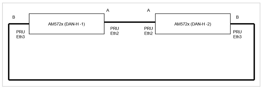
To test HSR, user would need two AM572x EVMs.
Setup HSR Ring network as per diagram below. Connect the PRU2ETH0 (See the marking on the EVM) Ethernet ports of the two EVMs together (corresponds to Linux interface eth2) as shown below. Similarly, connect the PRU2ETH1 ports (Linux interface eth3) as well.
Boot the EVMs using the pre-built images from the Processor SDK release. These images are built with Linux HSR/PRP driver enabled. Login to the console using root user name.
Now change Ethernet type to HSR as explained Changing protocol at PRU Ethernet
Note the MAC Address of eth2 at DAN-H-1(Say MAC-A) using the ifconfig command. Do ifconfig eth2 at the Linux console of DAN-H-1
Note the MAC Address of eth2 at DAN-H-2(Say MAC-B) using the ifconfig command. Do ifconfig eth2 at the Linux console of DAN-H-2
ifconfig eth2 down
ifconfig eth3 down
ifconfig eth3 hw ether <MAC-A>
ifconfig eth2 up
ifconfig eth3 up
ip link add name hsr0 type hsr slave1 eth2 slave2 eth3 supervision 45 version 1
ifconfig hsr0 <IP Address of hsr interface at DAN-H-1> up
Repeat the above steps for DAN-H-2, but this time use MAC-B in step 4.3 above. And use IP Address from the same subnet as that of DAN-H-1 hsr interface hsr0.
For example use Ip Address 192.168.2.10 for DAN-H-1 and 192.168.2.20 for DAN-H-2. Assume CPSW ports at the EVM are on a different Subnet than the HSR interface.
Once both hsr0 interfaces are created, user should be able to do a ping from DAN-H-1 to DAN-H-2 or vice-versa. Disconnect Ethernet cable at eth2 or eth3. The Ping should continue to go through. User could run iperf between the two HSR interfaces and test the iperf is not affected when one of the cable is disconnected. This verifies redundancy.
A Sample script that automates the steps using eth2 and eth3 is provided below
#!/bin/sh
#<args: <hsr|prp>
# on AM57x only
# Dual EMAC to HSR/PRP on DUT-A
if [ "$#" != "1" ]
then
       echo "$0 <hsr|prp>"
       exit
fi

if [ "$1" != "hsr" ] && [ "$1" != "prp" ]
then
       echo "$0 <hsr|prp>"
       exit
fi

if [ "$1" == "hsr" ]
then
       if=hsr0
else
       if=prp0
fi

ifa=eth2
ifb=eth3
ip=192.168.2.10
mac=70:FF:76:1C:02:0A
echo "ip=$ip"
echo "if=$if"
echo "mac=$mac"
echo "slave-a=$ifa"
echo "slave-b=$ifb"

ifconfig $ifa 0.0.0.0 down
ifconfig $ifb 0.0.0.0 down
ifconfig $ifa hw ether $mac
ifconfig $ifb hw ether $mac
if [ "$1" == "hsr" ]
then
       ethtool -K $ifa hsr-rx-offload on
       ethtool -K $ifb hsr-rx-offload on
else
       ethtool -K $ifa prp-rx-offload on
       ethtool -K $ifb prp-rx-offload on
fi

ifconfig $ifa up
ifconfig $ifb up
if [ "$1" == "hsr" ]
then
       ip link add name $if type hsr slave1 $ifa slave2 $ifb supervision 45 version 1 sv_vid 3 sv_pcp 7 sv_dei 0
else
       ip link add name $if type hsr slave1 $ifa slave2 $ifb supervision 45 proto 1 sv_vid 3 sv_pcp 7 sv_dei 0
fi

ifconfig $if $ip
ifconfig $if
ifconfig $ifa
ifconfig $ifb
To customize the script for another device, please change the mac and ip variables. Similarly to use a different vid, pcp and dei for supervision frame VLAN, change the same in the above script. To delete the hsr or prp interface, user may use ip link command as
ip link delete <hsr or prp interface name>. Example for hsr0 interface name, user type
ip link delete hsr0
Note that the Ethernet interfaces should be updated with original MAC address after this as below assuming eth2 and eth3 interfaces
ifconfig eth2 0.0.0.0 down
ifconfig eth3 0.0.0.0 down
ifconfig eth2 hw ether 70:FF:76:1C:02:0A
ifconfig eth3 hw ether 70:FF:76:1C:02:0B
DAN-H-1
root@am57xx-evm:~# ifconfig eth2
 eth2      Link encap:Ethernet  HWaddr 70:FF:76:1C:0F:8D
           BROADCAST MULTICAST  MTU:1500  Metric:1
           RX packets:0 errors:0 dropped:0 overruns:0 frame:0
           TX packets:0 errors:0 dropped:0 overruns:0 carrier:0
           collisions:0 txqueuelen:1000
           RX bytes:0 (0.0 B)  TX bytes:0 (0.0 B)
root@am57xx-evm:~#
root@am57xx-evm:~# <script to setup HSR interface>
[  504.221620] 001: remoteproc remoteproc6: powering up 4b2b4000.pru
[  504.223172] 001: remoteproc remoteproc6: Booting fw image ti-pruss/am57xx-pru0-prueth-fw.elf, size 7228
[  504.223386] 001: pru-rproc 4b2b4000.pru: configured system_events[63-0] = 00000600,04500000
[  504.223394] 001: pru-rproc 4b2b4000.pru: configured intr_channels = 0x000000d5 host_intr = 0x00000155
[  504.223403] 001: remoteproc remoteproc6: remote processor 4b2b4000.pru is now up
[  504.223750] 001: net eth2: started
[  504.267344] 001: pru-rproc 4b2b4000.pru: unconfigured system_events[63-0] = 00000600,04500000
[  504.267355] 001: pru-rproc 4b2b4000.pru: unconfigured host_intr = 0x00000155
[  504.267363] 001: remoteproc remoteproc6: stopped remote processor 4b2b4000.pru
[  504.267391] 001: net eth2: stopped
[  504.280076] 001: remoteproc remoteproc7: powering up 4b2b8000.pru
[  504.281224] 001: remoteproc remoteproc7: Booting fw image ti-pruss/am57xx-pru1-prueth-fw.elf, size 7256
[  504.281467] 001: pru-rproc 4b2b8000.pru: configured system_events[63-0] = 00600000,08a00000
[  504.281475] 001: pru-rproc 4b2b8000.pru: configured intr_channels = 0x0000032a host_intr = 0x000002aa
[  504.281483] 001: remoteproc remoteproc7: remote processor 4b2b8000.pru is now up
[  504.281846] 001: net eth3: started
[  504.327322] 001: pru-rproc 4b2b8000.pru: unconfigured system_events[63-0] = 00600000,08a00000
[  504.327333] 001: pru-rproc 4b2b8000.pru: unconfigured host_intr = 0x000002aa
[  504.327340] 001: remoteproc remoteproc7: stopped remote processor 4b2b8000.pru
[  504.327367] 001: net eth3: stopped
[  504.378975] 001: remoteproc remoteproc6: powering up 4b2b4000.pru
[  504.385687] 001: remoteproc remoteproc6: Booting fw image ti-pruss/am57xx-pru0-pruhsr-fw.elf, size 8252
[  504.385901] 001: pru-rproc 4b2b4000.pru: configured system_events[63-0] = 00000600,00900000
[  504.385909] 001: pru-rproc 4b2b4000.pru: configured intr_channels = 0x00000095 host_intr = 0x00000115
[  504.385917] 001: remoteproc remoteproc6: remote processor 4b2b4000.pru is now up
[  504.385935] 001: remoteproc remoteproc7: powering up 4b2b8000.pru
[  504.391421] 001: remoteproc remoteproc7: Booting fw image ti-pruss/am57xx-pru1-pruhsr-fw.elf, size 7920
[  504.391648] 001: pru-rproc 4b2b8000.pru: configured system_events[63-0] = 00600000,01200000
[  504.391656] 001: pru-rproc 4b2b8000.pru: configured intr_channels = 0x0000012a host_intr = 0x0000022a
[  504.391664] 001: remoteproc remoteproc7: remote processor 4b2b8000.pru is now up
[  504.392181] 001: net eth2: started
[  504.406518] 001: net eth3: started
[  504.563871] 001: hsr0: Slave A (eth2) is not up; please bring it up to get a fully working HSR network
[  504.563884] 001: hsr0: Slave B (eth3) is not up; please bring it up to get a fully working HSR network
[  505.951046] 001: prueth pruss2_eth eth2: Link is Up - 100Mbps/Full - flow control off
[  505.951074] 001: IPv6: ADDRCONF(NETDEV_CHANGE): eth2: link becomes ready
[  505.951418] 001: IPv6: ADDRCONF(NETDEV_CHANGE): hsr0: link becomes ready
[  505.962594] 001: prueth pruss2_eth eth3: Link is Up - 100Mbps/Full - flow control off
[  505.962620] 001: IPv6: ADDRCONF(NETDEV_CHANGE): eth3: link becomes ready
[  511.334554] 001: prueth pruss2_eth eth2: Link is Down
[  511.397766] 001: prueth pruss2_eth eth3: Link is Down
[  513.106896] 001: prueth pruss2_eth eth2: Link is Up - 100Mbps/Full - flow control off
[  513.114243] 001: prueth pruss2_eth eth3: Link is Up - 100Mbps/Full - flow control off
root@am57xx-evm:~#
root@am57xx-evm:~# ifconfig hsr0
hsr0      Link encap:Ethernet  HWaddr 70:FF:76:1C:0E:0D
          inet addr:192.168.2.20  Bcast:192.168.2.255  Mask:255.255.255.0
          inet6 addr: fe80::72ff:76ff:fe1c:e0d/64 Scope:Link
          UP BROADCAST RUNNING MULTICAST  MTU:1500  Metric:1
          RX packets:15 errors:0 dropped:0 overruns:0 frame:0
          TX packets:35 errors:0 dropped:0 overruns:0 carrier:0
          collisions:0 txqueuelen:1000
          RX bytes:1200 (1.1 KiB)  TX bytes:5433 (5.3 KiB)
root@am57xx-evm:~# cat /proc/hsr0/node-table
   Remote nodes in network: 1
   Node[0]:
   MAC ADDR: d6:ab:09:0d:f0:e5
   DANH
   Time Last Seen: RxA=0 RxB=0
root@am57xx-evm:~# cat /proc/hsr0/lre-stats
   LRE statistics:
   Rx Offloaded: 1
       lreTxA: 15915369
       lreTxB: 15915369
       lreTxC: 673
       lreErrWrongLanA: 207816
       lreErrWrongLanB: 207789
       lreErrWrongLanC: 0
       lreRxA: 0
       lreRxB: 27
       lreRxC: 15707590
       lreErrorsA: 0
       lreErrorsB: 0
       lreErrorsC: 0
       lreNodes: 1
       lreProxyNodes: 0
       lreUniqueRxA: 0
       lreUniqueRxB: 0
       lreUniqueRxC: 0
       lreDuplicateRxA: 0
       lreDuplicateRxB: 0
       lreDuplicateRxC: 0
       lreMultiRxA: 0
       lreMultiRxB: 0
       lreMultiRxC: 0
       lreOwnRxA: 0
       lreOwnRxB: 0
DAN-H-2
root@am57xx-evm:~# ifconfig eth2
eth2      Link encap:Ethernet  HWaddr D6:AB:09:0D:F0:E5
          BROADCAST MULTICAST  MTU:1500  Metric:1
          RX packets:0 errors:0 dropped:0 overruns:0 frame:0
          TX packets:0 errors:0 dropped:0 overruns:0 carrier:0
          collisions:0 txqueuelen:1000
          RX bytes:0 (0.0 B)  TX bytes:0 (0.0 B)
root@am57xx-evm:~#
root@am57xx-evm:~# <script to setup HSR interface> (#different MAC address than in DAN-H-1)
[  520.528397] 000: remoteproc remoteproc6: powering up 4b2b4000.pru
[  520.529991] 000: remoteproc remoteproc6: Booting fw image ti-pruss/am57xx-pru0-prueth-fw.elf, size 7228
[  520.530205] 000: pru-rproc 4b2b4000.pru: configured system_events[63-0] = 00000600,04500000
[  520.530213] 000: pru-rproc 4b2b4000.pru: configured intr_channels = 0x000000d5 host_intr = 0x00000155
[  520.530221] 000: remoteproc remoteproc6: remote processor 4b2b4000.pru is now up
[  520.530571] 000: net eth2: started
[  520.579114] 000: pru-rproc 4b2b4000.pru: unconfigured system_events[63-0] = 00000600,04500000
[  520.579125] 000: pru-rproc 4b2b4000.pru: unconfigured host_intr = 0x00000155
[  520.579132] 000: remoteproc remoteproc6: stopped remote processor 4b2b4000.pru
[  520.579158] 000: net eth2: stopped
[  520.589374] 000: remoteproc remoteproc7: powering up 4b2b8000.pru
[  520.593239] 000: remoteproc remoteproc7: Booting fw image ti-pruss/am57xx-pru1-prueth-fw.elf, size 7256
[  520.593461] 000: pru-rproc 4b2b8000.pru: configured system_events[63-0] = 00600000,08a00000
[  520.593469] 000: pru-rproc 4b2b8000.pru: configured intr_channels = 0x0000032a host_intr = 0x000002aa
[  520.593477] 000: remoteproc remoteproc7: remote processor 4b2b8000.pru is now up
[  520.593831] 000: net eth3: started
[  520.633506] 000: pru-rproc 4b2b8000.pru: unconfigured system_events[63-0] = 00600000,08a00000
[  520.633518] 000: pru-rproc 4b2b8000.pru: unconfigured host_intr = 0x000002aa
[  520.633525] 000: remoteproc remoteproc7: stopped remote processor 4b2b8000.pru
[  520.633554] 000: net eth3: stopped
[  520.698838] 000: remoteproc remoteproc6: powering up 4b2b4000.pru
[  520.700225] 000: remoteproc remoteproc6: Booting fw image ti-pruss/am57xx-pru0-pruhsr-fw.elf, size 8252
[  520.700439] 000: pru-rproc 4b2b4000.pru: configured system_events[63-0] = 00000600,00900000
[  520.700448] 000: pru-rproc 4b2b4000.pru: configured intr_channels = 0x00000095 host_intr = 0x00000115
[  520.700456] 000: remoteproc remoteproc6: remote processor 4b2b4000.pru is now up
[  520.700473] 000: remoteproc remoteproc7: powering up 4b2b8000.pru
[  520.701476] 000: remoteproc remoteproc7: Booting fw image ti-pruss/am57xx-pru1-pruhsr-fw.elf, size 7920
[  520.701653] 000: pru-rproc 4b2b8000.pru: configured system_events[63-0] = 00600000,01200000
[  520.701660] 000: pru-rproc 4b2b8000.pru: configured intr_channels = 0x0000012a host_intr = 0x0000022a
[  520.701668] 000: remoteproc remoteproc7: remote processor 4b2b8000.pru is now up
[  520.702171] 000: net eth2: started
[  520.726685] 000: net eth3: started
[  520.922529] 000: hsr0: Slave A (eth2) is not up; please bring it up to get a fully working HSR network
[  520.922541] 000: hsr0: Slave B (eth3) is not up; please bring it up to get a fully working HSR network
root@am57xx-evm:~#
root@am57xx-evm:~#  ping 192.168.2.10
PING 192.168.2.10 (192.168.2.10): 56 data bytes
64 bytes from 192.168.2.10: seq=0 ttl=64 time=0.618 ms
64 bytes from 192.168.2.10: seq=1 ttl=64 time=0.341 ms
root@am57xx-evm:~#
root@am57xx-evm:~# cat /proc/hsr0/node-table
   Remote nodes in network: 1
   Node[0]:
   MAC ADDR: 70:ff:76:1c:0f:8d
   DANH
   Time Last Seen: RxA=0 RxB=0
4.2.4.13.5. PRP Testing
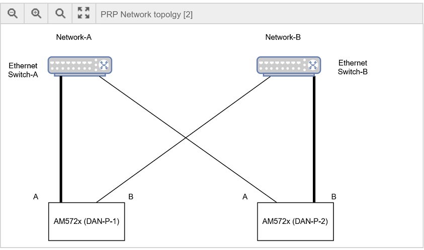
For Testing PRP, user is required to use the setup shown in the above diagram. A DAN-P is attached to two independent networks (A and B) each of which is shown as a separate Ethernet switch. Do the following steps to setup the prp interface. Note that in the below example Linux interface eth2 is Link-A (slave1 in ip link command) and eth3 is Link-B (slave2 in ip link command). Link-A is the Ethernet cable that connects DUT to Switch A and Link-B is the Ethernet cable that connects to Switch-B. This is very important for PRP as swapping them is an incorrect connection and can produce undesirable results. Alternately user may connect Link-A to Link-A and Link-B to Link-B which is the simplified setup where switches are replaced with ethernet cable.
Connect the DAN-P-1 EVM, PRU2ETH0 (marking on EVM) to a port at Ethernet switch A and PRU2ETH1 to a port at Ethernet switch B
Similarly, connect DAN-P-2 EVM, PRU2ETH0 to a port at Ethernet switch A and PRU2ETH1 to a port at Ethernet switch B
Now change Ethernet type to PRP as explained Changing protocol at PRU Ethernet
Boot the EVMs using the pre-built images from the Processor SDK release. These images are built with Linux HSR/PRP driver enabled. Login to the console using root user name.
This time user may use the script to create the prp interface. Use different MAC address at each DUT
Same sample script mentioned earlier for HSR Testing can be used for PRP interface with command line parameter prp specified as argument.
Sample logs are shown below:
DAN-P-1
root@am57xx-evm:~# ifconfig eth2
   eth2      Link encap:Ethernet  HWaddr 70:FF:76:1C:0F:8D
             inet6 addr: fe80::72ff:76ff:fe1c:f8d%3068183320/64 Scope:Link
             UP BROADCAST RUNNING MULTICAST  MTU:1500  Metric:1
             RX packets:80429 errors:0 dropped:0 overruns:0 frame:593
             TX packets:40905 errors:0 dropped:0 overruns:0 carrier:0
             collisions:0 txqueuelen:1000
             RX bytes:121704175 (116.0 MiB)  TX bytes:2716445 (2.5 MiB)
root@am57xx-evm:~#
root@am57xx-evm:~# <script to create prp interface>
[   86.546039] 001: remoteproc remoteproc6: powering up 4b2b4000.pru
[   86.547682] 001: remoteproc remoteproc6: Booting fw image ti-pruss/am57xx-pru0-prueth-fw.elf, size 7228
[   86.547898] 001: pru-rproc 4b2b4000.pru: configured system_events[63-0] = 00000600,04500000
[   86.547906] 001: pru-rproc 4b2b4000.pru: configured intr_channels = 0x000000d5 host_intr = 0x00000155
[   86.547915] 001: remoteproc remoteproc6: remote processor 4b2b4000.pru is now up
[   86.548261] 001: net eth2: started
[   86.602785] 001: pru-rproc 4b2b4000.pru: unconfigured system_events[63-0] = 00000600,04500000
[   86.602798] 001: pru-rproc 4b2b4000.pru: unconfigured host_intr = 0x00000155
[   86.602806] 001: remoteproc remoteproc6: stopped remote processor 4b2b4000.pru
[   86.602835] 001: net eth2: stopped
[   86.611607] 001: remoteproc remoteproc7: powering up 4b2b8000.pru
[   86.623565] 001: remoteproc remoteproc7: Booting fw image ti-pruss/am57xx-pru1-prueth-fw.elf, size 7256
[   86.623814] 001: pru-rproc 4b2b8000.pru: configured system_events[63-0] = 00600000,08a00000
[   86.623823] 001: pru-rproc 4b2b8000.pru: configured intr_channels = 0x0000032a host_intr = 0x000002aa
[   86.623831] 001: remoteproc remoteproc7: remote processor 4b2b8000.pru is now up
[   86.624199] 001: net eth3: started
[   86.662750] 001: pru-rproc 4b2b8000.pru: unconfigured system_events[63-0] = 00600000,08a00000
[   86.662761] 001: pru-rproc 4b2b8000.pru: unconfigured host_intr = 0x000002aa
[   86.662769] 001: remoteproc remoteproc7: stopped remote processor 4b2b8000.pru
[   86.662799] 001: net eth3: stopped
Actual changes:
l2-fwd-offload: off [requested on]
prp-rx-offload: on
[   86.721664] 001: remoteproc remoteproc6: powering up 4b2b4000.pru
[   86.745026] 001: remoteproc remoteproc6: Booting fw image ti-pruss/am57xx-pru0-pruprp-fw.elf, size 7736
[   86.745242] 001: pru-rproc 4b2b4000.pru: configured system_events[63-0] = 00000600,00900000
[   86.745251] 001: pru-rproc 4b2b4000.pru: configured intr_channels = 0x00000095 host_intr = 0x00000115
[   86.745260] 001: remoteproc remoteproc6: remote processor 4b2b4000.pru is now up
[   86.745278] 001: remoteproc remoteproc7: powering up 4b2b8000.pru
[   86.746786] 001: remoteproc remoteproc7: Booting fw image ti-pruss/am57xx-pru1-pruprp-fw.elf, size 7616
[   86.746964] 001: pru-rproc 4b2b8000.pru: configured system_events[63-0] = 00600000,01200000
[   86.746971] 001: pru-rproc 4b2b8000.pru: configured intr_channels = 0x0000012a host_intr = 0x0000022a
[   86.746979] 001: remoteproc remoteproc7: remote processor 4b2b8000.pru is now up
[   86.747477] 001: net eth2: started
[   86.756707] 001: net eth3: started
[   86.938973] 001: prp0: Slave A (eth2) is not up; please bring it up to get a fully working HSR network
[   86.938985] 001: prp0: Slave B (eth3) is not up; please bring it up to get a fully working HSR network
[   88.336697] 001: prueth pruss2_eth eth3: Link is Up - 100Mbps/Full - flow control off
[   88.336726] 001: IPv6: ADDRCONF(NETDEV_CHANGE): eth3: link becomes ready
[   88.337060] 001: IPv6: ADDRCONF(NETDEV_CHANGE): prp0: link becomes ready
[   88.342023] 001: prueth pruss2_eth eth2: Link is Up - 100Mbps/Full - flow control off
[   88.342043] 001: IPv6: ADDRCONF(NETDEV_CHANGE): eth2: link becomes ready
root@am57xx-evm:~#
root@am57xx-evm:~# ifconfig prp0
prp0      Link encap:Ethernet  HWaddr 70:FF:76:1C:16:EF
          inet addr:192.168.2.10  Bcast:192.168.2.255  Mask:255.255.255.0
          inet6 addr: fe80::72ff:76ff:fe1c:16ef/64 Scope:Link
          UP BROADCAST RUNNING MULTICAST  MTU:1500  Metric:1
          RX packets:58 errors:0 dropped:0 overruns:0 frame:0
          TX packets:62 errors:0 dropped:0 overruns:0 carrier:0
          collisions:0 txqueuelen:1000
          RX bytes:11462 (11.1 KiB)  TX bytes:8138 (7.9 KiB)
root@am57xx-evm:/# cat /proc/prp0/node-table
Remote nodes in network: 1
Node[0]:
MAC ADDR: 2a:da:8c:50:1b:86
DANP
Time Last Seen: RxA=0 RxB=0
root@am57xx-evm:~#
root@am57xx-evm:/# cat /proc/prp0/lre-stats
   LRE statistics:
   Rx Offloaded: 1

       lreTxA: 208128
       lreTxB: 208128
       lreTxC: 31305063
       lreErrWrongLanA: 0
       lreErrWrongLanB: 0
       lreErrWrongLanC: 0
       lreRxA: 0
       lreRxB: 0
       lreRxC: 208
       lreErrorsA: 0
       lreErrorsB: 0
       lreErrorsC: 0
       lreNodes: 1
       lreProxyNodes: 0
       lreUniqueRxA: 0
       lreUniqueRxB: 0
       lreUniqueRxC: 0
       lreDuplicateRxA: 0
       lreDuplicateRxB: 0
       lreDuplicateRxC: 0
       lreMultiRxA: 0
       lreMultiRxB: 0
       lreMultiRxC: 0
       lreOwnRxA: 0
       lreOwnRxB: 0
DAN-P-2
root@am57xx-evm:~# ifconfig eth2
eth2      Link encap:Ethernet  HWaddr 2A:DA:8C:50:1B:86
          inet6 addr: fe80::28da:8cff:fe50:1b86%3068203800/64 Scope:Link
          UP BROADCAST RUNNING MULTICAST  MTU:1500  Metric:1
          RX packets:40881 errors:0 dropped:10 overruns:0 frame:64
          TX packets:81022 errors:0 dropped:3528075 overruns:0 carrier:0
          collisions:0 txqueuelen:1000
          RX bytes:2718950 (2.5 MiB)  TX bytes:122601929 (116.9 MiB)
root@am57xx-evm:~# <script to create prp interface> Use a different MAC address than DAN-P-1
root@am57xx-evm:~# ifconfig prp0
prp0      Link encap:Ethernet  HWaddr 70:FF:76:1C:0E:0D
          inet addr:192.168.2.20  Bcast:192.168.2.255  Mask:255.255.255.0
          inet6 addr: fe80::72ff:76ff:fe1c:e0d/64 Scope:Link
          UP BROADCAST RUNNING MULTICAST  MTU:1500  Metric:1
          RX packets:4 errors:0 dropped:0 overruns:0 frame:0
          TX packets:38 errors:0 dropped:0 overruns:0 carrier:0
          collisions:0 txqueuelen:1000
          RX bytes:224 (224.0 B)  TX bytes:5963 (5.8 KiB)
root@am57xx-evm:~#
root@am57xx-evm:~# cat /proc/prp0/node-table
Remote nodes in network: 1
Node[0]:
MAC ADDR: 70:ff:76:1c:0e:0d
DANP
Time Last Seen: RxA=882 RxB=818
root@am57xx-evm:~#
root@am57xx-evm:/# cat /proc/prp0/lre-stats
LRE statistics:
       Rx Offloaded: 1
       lreTxA: 208128
       lreTxB: 208128
       lreTxC: 31305063
       lreErrWrongLanA: 0
       lreErrWrongLanB: 0
       lreErrWrongLanC: 0
       lreRxA: 0
       lreRxB: 0
       lreRxC: 208
       lreErrorsA: 0
       lreErrorsB: 0
       lreErrorsC: 0
       lreNodes: 1
       lreProxyNodes: 0
       lreUniqueRxA: 0
       lreUniqueRxB: 0
       lreUniqueRxC: 0
       lreDuplicateRxA: 0
       lreDuplicateRxB: 0
       lreDuplicateRxC: 0
       lreMultiRxA: 0
       lreMultiRxB: 0
       lreMultiRxC: 0
       lreOwnRxA: 0
       lreOwnRxB: 0
4.2.4.14. Performance Test and Logs
Boot up two AM571x/572x EVM to configure PRU Ethernet in HSR or PRP mode as described at Testing HSR/PRP Firmware Offload They are connected over eth2 and eth3 as described in HSR Testing or PRP Testing
UDP
Server side (hsr)
Create HSR interface and raise the priority of softirq/0 thread
root@am57xx-evm:~# <script to switch to HSR>
root@am57xx-evm:~# chrt -f -p 40 9
root@am57xx-evm:~# iperf3 -s -i60&

[1] 1336

root@am57xx-evm:~#
-----------------------------------------------------------
Server listening on 5201
-----------------------------------------------------------
root@am57xx-evm:~# Accepted connection from 192.168.2.20, port 44770
[  5] local 192.168.2.10 port 5201 connected to 192.168.2.20 port 38368
root@am57xx-evm:~# [ ID] Interval           Transfer     Bitrate         Jitter    Lost/Total Datagrams
[  5]   0.00-60.00  sec   629 MBytes  88.0 Mbits/sec  0.002 ms  0/448363 (0%)
[  5]  60.00-120.00 sec   629 MBytes  88.0 Mbits/sec  0.003 ms  0/448369 (0%)
[  5] 120.00-180.00 sec   629 MBytes  88.0 Mbits/sec  0.009 ms  0/448370 (0%)
[  5] 180.00-240.00 sec   629 MBytes  88.0 Mbits/sec  0.007 ms  0/448371 (0%)
[  5] 240.00-300.00 sec   629 MBytes  88.0 Mbits/sec  0.005 ms  0/448370 (0%)
[  5] 300.00-360.00 sec   629 MBytes  88.0 Mbits/sec  0.003 ms  0/448373 (0%)
[  5] 360.00-420.00 sec   629 MBytes  88.0 Mbits/sec  0.013 ms  0/448372 (0%)
[  5] 420.00-480.00 sec   629 MBytes  88.0 Mbits/sec  0.039 ms  0/448374 (0%)
[  5] 480.00-540.00 sec   629 MBytes  88.0 Mbits/sec  0.009 ms  0/448373 (0%)
[  5] 540.00-600.00 sec   629 MBytes  88.0 Mbits/sec  0.007 ms  0/448358 (0%)
- - - - - - - - - - - - - - - - - - - - - - - - -
[ ID] Interval           Transfer     Bitrate         Jitter    Lost/Total Datagrams

[  5]   0.00-600.00 sec  6.15 GBytes  88.0 Mbits/sec  0.007 ms  0/4483693 (0%)  receiver

-----------------------------------------------------------
Server listening on 5201
-----------------------------------------------------------
Client side (hsr)
Create HSR interface and raise the priority of softirq/0 thread
root@am57xx-evm:~# <script to setup hsr>
root@am57xx-evm:~#ping -c2 192.168.2.10
PING 192.168.2.10 (192.168.2.10): 56 data bytes
64 bytes from 192.168.2.10: seq=0 ttl=64 time=0.618 ms
64 bytes from 192.168.2.10: seq=1 ttl=64 time=0.341 ms
root@am57xx-evm:~# chrt -f -p 40 9
root@am57xx-evm:~# iperf3 -c 192.168.2.10 -u -b88M -l1472 -t600 -i60&
[1] 1330
root@am57xx-evm:~# warning: UDP block size 1472 exceeds TCP MSS 1448, may result in fragmentation / drops
Connecting to host 192.168.2.10, port 5201
[  5] local 192.168.2.20 port 38368 connected to 192.168.2.10 port 5201
root@am57xx-evm:~# [ ID] Interval           Transfer     Bitrate         Total Datagrams
[  5]   0.00-60.00  sec   629 MBytes  88.0 Mbits/sec  448369
[  5]  60.00-120.00 sec   629 MBytes  88.0 Mbits/sec  448363
[  5] 120.00-180.00 sec   629 MBytes  88.0 Mbits/sec  448370
[  5] 180.00-240.00 sec   629 MBytes  88.0 Mbits/sec  448375
[  5] 240.00-300.00 sec   629 MBytes  88.0 Mbits/sec  448368
[  5] 300.00-360.00 sec   629 MBytes  88.0 Mbits/sec  448371
[  5] 360.00-420.00 sec   629 MBytes  88.0 Mbits/sec  448368
[  5] 420.00-480.00 sec   629 MBytes  88.0 Mbits/sec  448371
[  5] 480.00-540.00 sec   629 MBytes  88.0 Mbits/sec  448370
[  5] 540.00-600.00 sec   629 MBytes  88.0 Mbits/sec  448369
- - - - - - - - - - - - - - - - - - - - - - - - -
[ ID] Interval           Transfer     Bitrate         Jitter    Lost/Total Datagrams
[  5]   0.00-600.00 sec  6.15 GBytes  88.0 Mbits/sec  0.000 ms  0/4483694 (0%)  sender
[  5]   0.00-600.00 sec  6.15 GBytes  88.0 Mbits/sec  0.007 ms  0/4483693 (0%)  receiver
iperf Done.
[1]+  Done                    iperf3 -c 192.168.2.10 -u -b88M -l1472 -t600 -i60
For PRP, the steps are similar. Create prp interface and do similar settings.
4.2.4.15. Redundancy Test and Logs
For HSR and PRP redundancy is implemented using duplicate links and sending frame over both links and discarding the duplicate at the receive side. The test requires two DAN-P or DAN-H nodes connected over eth2 and eth3 Ethernet Links. Boot up the EVM and create HSR or PRP interfaces as described at Processor_SDK_Linux_HSR_PRP#Testing_HSR.2FPRP_Firmware_Offload. Do an iperf UDP test at 88Mbits/sec for MTU sized packets (size = 1472) and then pull out either eth2 or eth3 Ethernet cable. Make sure iperf stats doesn’t show packet loss during the test period. Here is the log for HSR that shows link failed during the test and there was no packet loss. Logs assume that iperf3 server runs on the other connected DUT.
root@am57xx-evm:~# iperf3 -c 192.168.2.20 -u -b90M -l1472 -t60&
[1] 1376
root@am57xx-evm:~# warning: UDP block size 1472 exceeds TCP MSS 1448, may result in fragmentation / drops
Connecting to host 192.168.2.20, port 5201

[  5] local 192.168.2.10 port 50289 connected to 192.168.2.20 port 5201
root@am57xx-evm:~# [ ID] Interval           Transfer     Bitrate         Total Datagrams
[  5]   0.00-1.00   sec  10.7 MBytes  90.0 Mbits/sec  7642
[  5]   1.00-2.00   sec  10.7 MBytes  90.0 Mbits/sec  7642
............... Cut----------------------------------------
[  5]  11.00-12.00  sec  10.7 MBytes  90.0 Mbits/sec  7643
[  5]  12.00-13.00  sec  10.7 MBytes  90.0 Mbits/sec  7644
[  5]  13.00-14.00  sec  10.7 MBytes  90.0 Mbits/sec  7640
[ 1131.770666] 000: prueth pruss2_eth eth2: No link to transmit
[ 1131.770666] 001: prueth pruss2_eth eth2: Link is Down
[ 1131.770679] 000: prueth pruss2_eth eth2: No link to transmit
[  5]  14.00-15.00  sec  10.7 MBytes  90.0 Mbits/sec  7645
[ 1133.525538] 001: prueth pruss2_eth eth2: Link is Up - 100Mbps/Full - flow control off
[  5]  15.00-16.00  sec  10.7 MBytes  90.0 Mbits/sec  7639
[  5]  16.00-17.00  sec  10.7 MBytes  90.0 Mbits/sec  7644
[  5]  17.00-18.00  sec  10.7 MBytes  90.0 Mbits/sec  7645
............... Cut----------------------------------------
[  5]  19.00-20.00  sec  10.7 MBytes  90.0 Mbits/sec  7640
[  5]  20.00-21.00  sec  10.7 MBytes  90.0 Mbits/sec  7645
[  5]  21.00-22.00  sec  10.7 MBytes  90.0 Mbits/sec  7643
[ 1140.570653] 001: prueth pruss2_eth eth3: Link is Down
[ 1140.570654] 000: prueth pruss2_eth eth3: No link to transmit
[  5]  22.00-23.00  sec  10.7 MBytes  89.4 Mbits/sec  7596
[  5]  23.00-24.00  sec  10.8 MBytes  90.5 Mbits/sec  7688
[ 1142.308893] 001: prueth pruss2_eth eth3: Link is Up - 100Mbps/Full - flow control off
[  5]  24.00-25.00  sec  10.7 MBytes  90.0 Mbits/sec  7643
[  5]  25.00-26.00  sec  10.7 MBytes  90.0 Mbits/sec  7643
[  5]  26.00-27.00  sec  10.7 MBytes  90.0 Mbits/sec  7644
[  5]  27.00-28.00  sec  10.7 MBytes  90.0 Mbits/sec  7640
............... Cut----------------------------------------
[  5]  59.00-60.00  sec  10.7 MBytes  90.0 Mbits/sec  7640
- - - - - - - - - - - - - - - - - - - - - - - - -
[ ID] Interval           Transfer     Bitrate         Jitter    Lost/Total Datagrams
[  5]   0.00-60.00  sec   644 MBytes  90.0 Mbits/sec  0.000 ms  0/458557 (0%)  sender
[  5]   0.00-60.00  sec   644 MBytes  90.0 Mbits/sec  0.011 ms  0/458556 (0%)  receiver
iperf Done.
[1]+  Done                    iperf3 -c 192.168.2.20 -u -b90M -l1472 -t60
Note that during the iperf3 session, the link failed 2 times, first eth2 and then eth3 and no packet drop observed.
4.2.4.16. Useful Commands
Linux HSR/PRP driver help commands
To dump lre_info such as sv_vid, sv_pcp, sv_dei, protocol etc used at the LRE of Linux HSR/PRP driver
cat /sys/kernel/debug/<hsr/prp-if_name>/lre_info example cat /sys/kernel/debug/hsr0/lre_info
To dump Node_Table
cat /proc/<hsr/prp-if_name>/node-table
To set hsr-mode - echo 1 > /proc/<hsr/prp-if_name>/hsr-mode
where 1 is for Mode-H Other values are 2 (Mode-N), 3 (Mode-T), 4 (Mode-U), 5 (Mode-M)
To clear node table - echo 1 > /proc/<hsr/prp-if_name>/clear-nt
To change duplicate detection mode - echo 1 > /proc/<hsr/prp-if_name>/dd-mode
To change duplicate list max resident time - echo 1000 > /proc/<hsr/prp-if_name>/dlrmt
To change prp transparent reception mode - echo 1 > /proc/<hsr/prp-if_name>/prp-tr
To disable SV frame transmission - echo 1 > /proc/<hsr/prp-if_name>/disable-sv_frame
To display lre_info to display things like, offload, SV vid, etc - cat /sys/kernel/debug/hsr/<hsr/prp-if_name>/lre_info
4.2.4.17. FAQ
How to disable udhcpc from sending DHCP request over prueth Ethernet interfaces (eth2-eth3) when it is configured to run HSR/PRP protocol in firmware?
Linux HSR/PRP driver uses the eth2/eth3 interface as slave interfaces to implement the protocol on top of it. Application is expected to send or receive packets over the hsr or prp lre interface also known as C port. However prueth also support plain Ethernet and the file system /etc/systemd/network/10-eth.network has a general rule to enable DHCP over all of the interface matching eth*. Modify the file to match unique name instead of generic name wild cards. For example to do DHCP over only eth0 interface, 10-eth.network may be modified as follows:-
root@am57xx-evm:~# cat /etc/systemd/network/10-eth.network
[Match]
Name=eth0
KernelCommandLine=!root=/dev/nfs

[Network]
DHCP=yes
To do DHCP over hsr0 or prp0 interfaces, user may add additional files to /etc/systemd/network/ one for each prp0 or hsr0 similar to eth0, by using a Match name string of hsr0 or prp0. More details on this is at [[6]]
Why do I see duplicate frames displayed by ping when I use PRP interface?
In ICSS firmware, PRU-0 is assumed to be for Link-A and PRU-1 for Link-B of a LRE in the case DANP. So in PRP case, Link-A should be connected network A and Link-B should be connected to Network B of a PRP network since net-id has to match as per duplicate detect alogrithm. If this convention is not followed, duplicate detection logic fails and duplicates are sent to upper layer causing ping application to complain about duplicates. So when creating prp interface, make sure ip link command parameter slave 1 use linux interface associated with PRU-0 and slave 2 use interface associated with PRU-1. Also when making network connection make sure that PRU-0 port is connected to Network A and PRU-1 port to Network B.