3.6.3.4. PRU_ICSSG Ethernet
3.6.3.4.1. Introduction
PRU_ICSSG Ethernet driver architecture is similar to PRU-ICSS Ethernet driver discussed at PRU-ICSS Ethernet
Driver is developed complying to Linux Driver model and implements netdev and NAPI APIs along with other basic driver functions. Driver supports multiple instances of ICSSG each of which has two slices. Each slice consists of a pair of Programmable Real-Time Units (PRUs), Auxillary Programmable Real-time Units (RTUs) and TX Programmable Real-Time Units (TX_PRUS). So each ICSSG instance supports two Ethernet interfaces i.e. one per slice.
One of the key difference in the driver implementation compared to PRU-ICSS driver is the use of UDMA driver interface and ring accelerator driver available on Keystone III SoC to send/receive frames between ARM Host processor and PRU_ICSSG. This allows for efficient moving of data and is more efficient than the shared memory transport used in PRU-ICSS.
3.6.3.4.2. Supported platforms
SoC |
Number of external ports |
|---|---|
AM65X |
3 x ICSSG, 6 Ports max |
AM64X |
2 x ICSSG, 4 Ports max |
Boards Supported
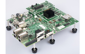
The AM65x Evaluation Module provides a platform to quickly start evaluation of Sitara™ Arm® Cortex®-A53 AM65x Processors (AM6548, AM6546, AM6528, AM6527, AM6526) and accelerate development for HMI, networking, patient monitoring, and other industrial applications. It is a development platform based on the quad core Cortex-A53, dual Cortex-R5F processor that is integrated with ample connectivity such as PCIe, USB 3.0/2.0, Gigabit Ethernet, PRU_ICSSG Ethernet, etc.
On this platform one CPSW Ethernet port and two ICSSG2 Ethernet ports are available for use.
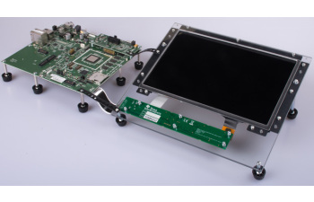
AM65x industrial development kit (IDK)
The AM65x Industrial Development Kit (IDK) is a development platform for evaluating the industrial communication and control capabilities of Sitara AM65x processors for applications in factory automation, drives, robotics, grid infrastructure, and more. AM65x processors include three PRU_ICSSG (Programmable Real-time Unit for Industrial Communications) sub-systems which can be used for gigabit industrial Ethernet protocols such as Profinet, EtherCAT, Ethernet/IP, and others.
On this platform one CPSW Ethernet port and two ICSSG2 Ethernet ports are available on the baseboard and 4 Ethernet ports, 2 each of ICSSG0 and ICSSG1 are available on the IDK application module.
3.6.3.4.3. Features supported
1G/100M/10M Full-Duplex Ethernet ports, Half-Duplex is not supported.
RGMII mode with TX delay (configured in DTS). RX delay is not supported and has to be provided by PHY.
Multiple TX queues (upto 4), single RX queue.
PTP Ordinary clock
PPS Out
Promiscuous mode
Features not supported
VLAN HW filtering
All-multi mode is always enabled
Multi-cast HW filtering
3.6.3.4.4. Driver Configuration
The TI Processor SDK has ICSSG driver enabled by default on supported platforms. In case of custom builds, please ensure following configs are enabled.
CONFIG_TI_PRUSS
CONFIG_REMOTEPROC
CONFIG_PRU_REMOTEPROC
CONFIG_TI_PRUSS_INTC
CONFIG_TI_DAVINCI_MDIO
CONFIG_TI_ICSS_IEP
CONFIG_TI_ICSSG_PRUETH
Module Build
Module build for the ICSSG driver is supported. To do this, use option ‘m’ for above configs, where applicable.
3.6.3.4.5. Device tree bindings
The DT bindings description can be found at:
3.6.3.4.6. User guide
3.6.3.4.6.1. Bringing Up interface
The network interface can be configured automatically depending on root file system or configured manually. Manual configuration:
ip addr add 192.168.1.1/24 dev eth1
ip link set dev eth1 up

< or >

ifconfig eth1 <ip> netmask <mask> up
3.6.3.4.6.2. Get information (ethtool)
3.6.3.4.6.2.1. Get driver information
The interface can be identified by using ethtool -i|--driver DEVNAME command.
It also provides some information about supported features.
~# ethtool -i eth1
driver: icssg-prueth
version:
firmware-version:
expansion-rom-version:
bus-info: pruss2_eth
supports-statistics: yes
supports-test: no
supports-eeprom-access: no
supports-register-dump: no
supports-priv-flags: no
3.6.3.4.6.2.2. Display standard information about device/link
Run ethtool DEVNAME command without parameters.
~# ethtool eth1
Settings for eth1:
        Supported ports: [ TP MII ]
        Supported link modes:   100baseT/Full
                                1000baseT/Full
        Supported pause frame use: No
        Supports auto-negotiation: Yes
        Supported FEC modes: Not reported
        Advertised link modes:  100baseT/Full
                                1000baseT/Full
        Advertised pause frame use: No
        Advertised auto-negotiation: Yes
        Advertised FEC modes: Not reported
        Link partner advertised link modes:  10baseT/Half 10baseT/Full
                                             100baseT/Half 100baseT/Full
                                             1000baseT/Full
        Link partner advertised pause frame use: Symmetric Receive-only
        Link partner advertised auto-negotiation: Yes
        Link partner advertised FEC modes: Not reported
        Speed: 1000Mb/s
        Duplex: Full
        Port: MII
        PHYAD: 0
        Transceiver: internal
        Auto-negotiation: on
        Current message level: 0x00007fff (32767)
                               drv probe link timer ifdown ifup rx_err tx_err tx_queued intr tx_done rx_status pktdata hw wol
        Link detected: yes
3.6.3.4.6.2.3. Display time stamping capabilities
The interface time stamping capabilities can be retrieved by using ethtool -T|--show-time-stamping DEVNAME command.
ethtool -T eth2
Time stamping parameters for eth2:
Capabilities:
     hardware-transmit     (SOF_TIMESTAMPING_TX_HARDWARE)
     software-transmit     (SOF_TIMESTAMPING_TX_SOFTWARE)
     hardware-receive      (SOF_TIMESTAMPING_RX_HARDWARE)
     software-receive      (SOF_TIMESTAMPING_RX_SOFTWARE)
     software-system-clock (SOF_TIMESTAMPING_SOFTWARE)
     hardware-raw-clock    (SOF_TIMESTAMPING_RAW_HARDWARE)
PTP Hardware Clock: 2
Hardware Transmit Timestamp Modes:
     off                   (HWTSTAMP_TX_OFF)
     on                    (HWTSTAMP_TX_ON)
Hardware Receive Filter Modes:
     none                  (HWTSTAMP_FILTER_NONE)
     all                   (HWTSTAMP_FILTER_ALL)
3.6.3.4.6.2.4. Show permanent hardware address
The interface permanent hardware address can be retrieved by using ethtool -P|--show-permaddr DEVNAME command.
~# ethtool -P eth1
Permanent address: 70:ff:76:1d:5c:64
3.6.3.4.6.2.5. Query Channels information
The interface DMA Channels information can be retrieved by using ethtool-l|--show-channels DEVNAME command.
# ethtool -l eth1
Channel parameters for eth1:
Pre-set maximums:
RX:             1
TX:             4
Other:          0
Combined:       0
Current hardware settings:
RX:             1
TX:             1
Other:          0
Combined:       0
3.6.3.4.6.2.6. Show adapter statistics
The interface statistics can be retrieved by using ethtool -S|--statistics DEVNAME command.
It displays statistic for the ethernet port.
# ethtool -S eth1
NIC statistics:
     rx_good_frames: 53
     rx_broadcast_frames: 1
     rx_multicast_frames: 53
     rx_crc_error_frames: 0
     rx_mii_error_frames: 0
     rx_odd_nibble_frames: 0
     rx_frame_max_size: 2000
     rx_max_size_error_frames: 0
     rx_frame_min_size: 64
     rx_min_size_error_frames: 11
     rx_overrun_frames: 0
     rx_class0_hits: 64
     rx_class1_hits: 0
     rx_class2_hits: 0
     rx_class3_hits: 0
     rx_class4_hits: 0
     rx_class5_hits: 0
     rx_class6_hits: 0
     rx_class7_hits: 0
     rx_class8_hits: 0
     rx_class9_hits: 0
     rx_class10_hits: 0
     rx_class11_hits: 0
     rx_class12_hits: 0
     rx_class13_hits: 0
     rx_class14_hits: 0
     rx_class15_hits: 0
     rx_smd_frags: 0
     rx_bucket1_size: 64
     rx_bucket2_size: 128
     rx_bucket3_size: 256
     rx_bucket4_size: 512
     rx_64B_frames: 2
     rx_bucket1_frames: 13
     rx_bucket2_frames: 30
     rx_bucket3_frames: 20
     rx_bucket4_frames: 1
     rx_bucket5_frames: 0
     rx_total_bytes: 7864
     rx_tx_total_bytes: 24165
     tx_good_frames: 98
     tx_broadcast_frames: 0
     tx_multicast_frames: 98
     tx_odd_nibble_frames: 0
     tx_underflow_errors: 0
     tx_frame_max_size: 2000
     tx_max_size_error_frames: 0
     tx_frame_min_size: 64
     tx_min_size_error_frames: 0
     tx_bucket1_size: 64
     tx_bucket2_size: 128
     tx_bucket3_size: 256
     tx_bucket4_size: 512
     tx_64B_frames: 0
     tx_bucket1_frames: 0
     tx_bucket2_frames: 68
     tx_bucket3_frames: 21
     tx_bucket4_frames: 9
     tx_bucket5_frames: 0
     tx_total_bytes: 12479
3.6.3.4.6.2.7. Show EEE settings
The interface EEE settings can be retrieved by using ethtool --show-eee DEVNAME command.
ethtool --show-eee eth1
EEE Settings for eth1:
   EEE status: disabled
   Tx LPI: disabled
   Supported EEE link modes:  100baseT/Full
               1000baseT/Full
   Advertised EEE link modes:  Not reported
   Link partner advertised EEE link modes:  100baseT/Full
                   1000baseT/Full
3.6.3.4.6.3. VLAN Config
VLAN can be added/deleted using ip or vconfig utility.
VLAN Add
ip link add link eth1 name eth1.5 type vlan id 5

< or >

vconfig add eth1 5
VLAN del
ip link del eth1.5

< or >

vconfig rem eth1 5
VLAN IP assigning
IP address can be assigned to the VLAN interface either via udhcpc
when a VLAN aware dhcp server is present or via static ip assigning
using ip or ifconfig.
Once VLAN is added, it will create a new entry in Ethernet interfaces like eth1.5, below is an example how it check the vlan interface
ip addr add 10.0.0.5/24 dev eth1.5

< or >

ifconfig eth1.5 10.0.0.5
....

~# ifconfig eth1.5
eth1.5    Link encap:Ethernet  HWaddr 70:FF:76:1D:5C:64
          inet addr:10.0.0.5  Bcast:10.255.255.255  Mask:255.0.0.0
          inet6 addr: fe80::72ff:76ff:fe1d:5c64/64 Scope:Link
          UP BROADCAST RUNNING MULTICAST  MTU:1500  Metric:1
          RX packets:0 errors:0 dropped:0 overruns:0 frame:0
          TX packets:45 errors:0 dropped:0 overruns:0 carrier:0
          collisions:0 txqueuelen:1000
          RX bytes:0 (0.0 B)  TX bytes:7590 (7.4 KiB)
VLAN Packet Send/Receive
To Send or receive packets with the VLAN tag, bind the socket to the proper Ethernet interface shown above and can send/receive via that socket-fd.
3.6.3.4.6.4. Multicast Add/Delete
Multicast MAC address can be added/deleted using ip maddr commands or Linux socket ioctl SIOCADDMULTI/SIOCDELMULTI.
Show muliticast address
~# ip maddr show eth1
3:      eth1
        link  33:33:00:00:00:01 users 2
        link  01:00:5e:00:00:01 users 2
        link  01:00:5e:00:00:fb users 2
        link  33:33:ff:1d:5c:64 users 2
        link  01:00:5e:00:00:fc users 2
        link  33:33:00:01:00:03 users 2
        link  33:33:00:00:00:fb users 2
        link  01:80:c2:00:00:21 users 2
        inet  224.0.0.252
        inet  224.0.0.251
        inet  224.0.0.1
        inet6 ff02::fb
        inet6 ff02::1:3
        inet6 ff02::1:ff1d:5c64
        inet6 ff02::1
        inet6 ff01::1
Add muliticast address
~# ip maddr add 01:00:5e:00:00:05 dev eth1
~# ip maddr show dev eth1
3:      eth1
        link  33:33:00:00:00:01 users 2
        link  01:00:5e:00:00:01 users 2
        link  01:00:5e:00:00:fb users 2
        link  33:33:ff:1d:5c:64 users 2
        link  01:00:5e:00:00:fc users 2
        link  33:33:00:01:00:03 users 2
        link  33:33:00:00:00:fb users 2
        link  01:80:c2:00:00:21 users 2
        link  01:00:5e:00:00:05 static
        inet  224.0.0.252
        inet  224.0.0.251
        inet  224.0.0.1
        inet6 ff02::fb
        inet6 ff02::1:3
        inet6 ff02::1:ff1d:5c64
        inet6 ff02::1
        inet6 ff01::1
Delete muliticast address
# ip maddr del 01:00:5e:00:00:05 dev eth1
3.6.3.4.6.5. Configure interface (ethtool)
3.6.3.4.6.5.1. Change generic options
The interface generic options can be configured by using ethtool -s|--change DEVNAME command.
The main purpose of this command is to configure physical link settings (PHY) like speed, duplex, auto-negotiation.
Below commands will be redirected to the phy driver:
# ethtool -s <dev>
[ speed %d ]
[ duplex half|full ]
[ autoneg on|off ]
[ wol p|u|m|b|a|g|s|d... ]
[ sopass %x:%x:%x:%x:%x:%x ]
Note
ICSSG Ethernet driver does not perform any kind of WOL specific actions or configurations.
Below is an example of forcing link speed to 100M and duplexity to full:
# ethtool -s eth1 duplex full speed 100
[   74.768324] icssg-prueth pruss2_eth eth1: Link is Down
[   78.592924] icssg-prueth pruss2_eth eth1: Link is Up - 100Mbps/Full - flow control off
3.6.3.4.6.5.2. Restart N-WAY (PHY) negotiation
The interface PHY auto-negotiation can be restarted by using ethtool -r|--negotiate DEVNAME command.
# ethtool -r eth1
[  273.151655] icssg-prueth pruss2_eth eth1: Link is Down
[  276.225423] icssg-prueth pruss2_eth eth1: Link is Up - 1Gbps/Full - flow control off
3.6.3.4.6.5.3. Set Channels parameters
The interface DMA channels parameters can be set by using ethtool -L\|--set-channels DEVNAME command.
It allows to control number of TX channels driver is allowed to work with at DMA level. The maximum number of TX channels is 4.
Supported options [ tx N ]:
# ethtool -L eth1 tx 4
3.6.3.4.6.6. PTP Ordinary Clock
The PRU Ethernet & IEP drivers implement the Linux PTP hardware clock subsystem APIs, the PRU-ICSS PTP clock can therefore be adjusted by using those standard APIs. See PTP hardware clock infrastructure for Linux for more details.
The IEP0 is used by PRU Ethernet driver and Firmware PTP hardware clock and shared between PRU Ethernet ports. The IEP1 is used for Firmware purposes.
The PTP Ordinary Clock (OC) implementation is provided by the linuxptp application.
ptp4l -f oc.cfg
oc.cfg is a ptp4l configuration file.
Example oc.cfg for OC,
[global]
tx_timestamp_timeout 10
logMinPdelayReqInterval -3
logSyncInterval -3
twoStepFlag 1
summary_interval 0
[eth1]
delay_mechanism P2P
network_transport L2
where eth1 is the intended PRU-ICSSG Ethernet port over which the OC functionality is provided.
See The Linux PTP Project for more details about linuxptp in general and ptp4l(8) - Linux man page about ptp4l configurations in particular.
Here is a sample screen display of ptp4l for PRU-ICSS Ethernet port as PTP/OC in slave mode:
# ptp4l -f oc.cfg -s -m
ptp4l[1255.613]: selected /dev/ptp2 as PTP clock
ptp4l[1255.664]: port 1: INITIALIZING to LISTENING on INITIALIZE
ptp4l[1255.665]: port 0: INITIALIZING to LISTENING on INITIALIZE
ptp4l[1255.665]: port 1: link up
ptp4l[1263.081]: selected best master clock 70ff76.fffe.1d5c64
ptp4l[1269.343]: selected best master clock 70ff76.fffe.1d5c64
ptp4l[1271.367]: port 1: new foreign master d494a1.fffe.8c36e9-1
ptp4l[1275.368]: selected best master clock d494a1.fffe.8c36e9
ptp4l[1275.368]: port 1: LISTENING to UNCALIBRATED on RS_SLAVE
ptp4l[1275.754]: port 1: UNCALIBRATED to SLAVE on MASTER_CLOCK_SELECTED
ptp4l[1276.381]: rms 789386424832367360 max 1578772849664738816 freq -60377 +/- 22862 delay   229 +/-   6
ptp4l[1277.385]: rms  473 max  729 freq -67059 +/- 642 delay   251 +/-   4
ptp4l[1278.389]: rms  792 max  830 freq -65620 +/- 211 delay   253 +/-   0
ptp4l[1279.393]: rms  504 max  667 freq -65335 +/-  17 delay   255 +/-   1
ptp4l[1280.397]: rms  166 max  271 freq -65484 +/-  59 delay   251 +/-   2
ptp4l[1281.401]: rms   26 max   42 freq -65649 +/-  34 delay   249 +/-   1
ptp4l[1282.405]: rms   43 max   50 freq -65727 +/-  10 delay   253 +/-   3
ptp4l[1283.409]: rms   26 max   39 freq -65739 +/-   6 delay   256 +/-   1
ptp4l[1284.412]: rms    5 max    7 freq -65725 +/-   3 delay   253 +/-   1
ptp4l[1285.416]: rms    5 max    7 freq -65717 +/-   6 delay   252 +/-   1
ptp4l[1286.420]: rms   11 max   14 freq -65698 +/-   6 delay   252 +/-   1
ptp4l[1287.424]: rms    8 max   12 freq -65693 +/-   5 delay   254 +/-   1
ptp4l[1288.427]: rms    7 max   12 freq -65687 +/-   4 delay   251 +/-   2
ptp4l[1289.430]: rms    4 max    8 freq -65686 +/-   3 delay   249 +/-   1
ptp4l[1290.434]: rms    5 max    8 freq -65693 +/-   7 delay   249 +/-   1
ptp4l[1291.438]: rms    4 max    9 freq -65696 +/-   5 delay   251 +/-   1
ptp4l[1292.441]: rms    7 max    9 freq -65682 +/-   5 delay   253 +/-   0
ptp4l[1293.445]: rms   11 max   14 freq -65667 +/-   4 delay   252 +/-   0
ptp4l[1294.448]: rms    8 max   14 freq -65662 +/-   5 delay   254 +/-   1
ptp4l[1295.452]: rms    6 max    8 freq -65659 +/-   5 delay   254 +/-   2
ptp4l[1296.456]: rms    3 max    7 freq -65657 +/-   2 delay   251 +/-   0
ptp4l[1297.459]: rms    4 max    5 freq -65661 +/-   6 delay   256 +/-   2
...
3.6.3.4.6.6.1. PPS Pulse Per Second support
PPS hardware pin is available only on the IDK application card i.e. ICSSG0 port 0 and ICSSG1 port 1. They are available at LEDs LD2 and LD5 respectively.
PPS can be tested using testptp.c tool.
To find out the PTP device number i.e. PTP Hardware Clock, use ethtool -T DEVNAME
Note
For PPS to work, the firmware needs to be running so the ICSSG network interface must be brought up.
To turn on PPS,
# ip link set dev eth1 up
# ./testptp -d /dev/ptp2 -P 1
pps for system time request okay
You should be able to see either LD2 or LD5 blink at 1 second interval.
To turn off PPS,
# ./testptp -d /dev/ptp2 -P 0
pps for system time request okay
3.6.3.4.7. Tips
3.6.3.4.7.1. Ethernet PHYs/MDIO bindings
The PRU_ICSSG Ethernet driver follows standard Linux DT bindings for MDIO bus, Ethernet controlers and PHYs which can be found at:
The existing TI Ethernet PHYs DT bindings:
3.6.3.4.7.2. Fixed link
The Linux PRU_ICSSG Ethernet driver provides support for ‘fixed-link’ MAC-MAC connection support which can be defined following standard Ethernet Controller Generic Binding for each “ethernet-miiX’ ICSSG port.
Note
Fixed link is use-case specific and got limited testing, so should be considered experimental.
Example:
icssg2_emac1: ethernet-mii1 {
   phy-mode = "rgmii-rxid";
   syscon-rgmii-delay = <&scm_conf 0x4124>;
   local-mac-address = [00 00 00 00 00 00];

   fixed-link {
      speed = <1000>;
      full-duplex;
   };
};
RGMII Fixed link
In case of RGMII MAC-MAC the ‘phy-mode’ DT property should be specifying properly for RGMII RX/TX delay configuration, taking into account ICSSG HW capability to provide only TX delay (which for some SoCs is not recommended to be disabled). Consult with SoC documentation (Data sheet, User guide) for supported RGMII RX/TX delay configurations.