3.2.4.6. DSS
Introduction
This page gives a basic description of DSS hardware, the Linux kernel drivers (omapdss and omapdrm) and various TI boards that use DSS. The technical reference manual (TRM) for the SoC in question, and the board documentation give more detailed descriptions.
This page applies to TI’s v4.19 kernel, but most of it is also valid for mainline and for older kernels. Some features may be missing from mainline.
Supported Devices
There are many DSS IP versions, all of which support slightly different set of features. All the DSS IP versions are supported by the same driver.
This page applies to the following TI SoCs or SoC families: OMAP2, OMAP3, OMAP4, OMAP5, AM5, AM4, DRA7.
Hardware Architecture
The Display Subsystem (DSS) is a hardware block responsible for fetching pixel data from memory and sending it to a display peripheral like an LCD panel or a HDMI monitor. DSS hardware can be divided into two major parts: 1) DISPC, which handles fetching the pixel data, doing color conversions, composition, and other pixel manipulation, and 2) encoders, which encode the raw pixel data to standard display signals, like HDMI or MIPI DPI. In addition to the SoC’s DSS, boards often contain external encoders (for example, DPI to DVI encoder) and display panels.
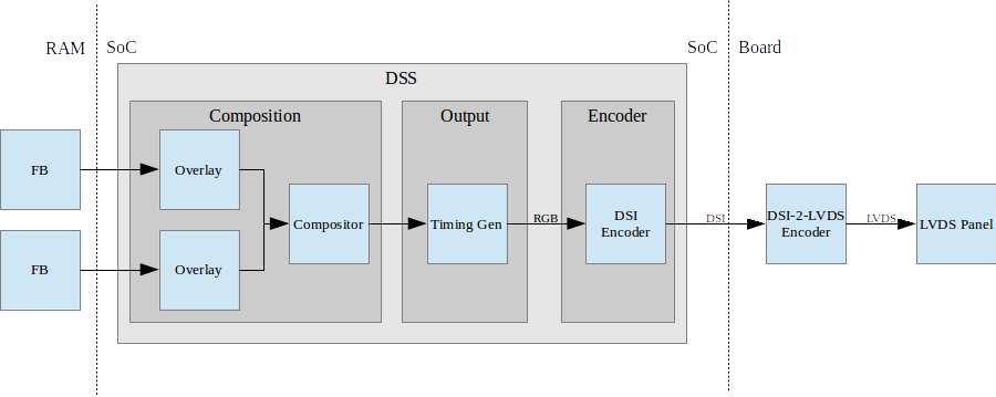
Simplified example setup where two overlays are merged into one output, which is encoded into DSI, then to LVDS, and shown on an LVDS panel.
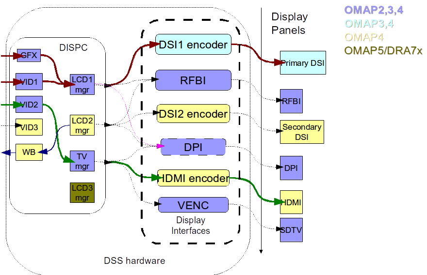
An overview of the DSS hardware. The arrows show how ovlerlays/pipelines are connected to overlay managers, which are further connected to encoders, which finally create an encoded pixel stream for display on to LCD or TV. The different colors of the blocks show the new sub-blocks added in subsequent DSS revisions
Display Controller (DISPC)
DISPC is the block which is responsible of fetching pixel data from the memory through DMA pipelines, and then create a pixel stream for the encoder. The pixel stream comprises of a composition of one or more image layers which we finally want to present on the display. DISPC can be split into 2 major sub-blocks:
Overlays
Overlays (or Pipelines or DMA channels) consist of the HW block which perform DMA to fetch image pixels (of different color formats) from RAM. Besides performing DMA, overlays perform other functions like replication, ARGB expansion, scaling, color conversion, VC1 range mapping on the input pixels before it’s passed on to the overlay manager. An overlay manager receives pixel data from one or more such pipelines, and performs the task of composing them and passing it on to the encoder.
Most DSS IP versions has two types of overlays: a GFX overlay and a number of VIDEO overlays. GFX overlay doesn’t support scaling or YUV color formats and are generally intended to display a user interface. VIDEO overlays support up/down scaling and YUV color formats. The number of overlays within DSS varies with the DSS IP version used in the SoC.
Overlay Managers (Compositors and timing generators)
Overlay managers are the blocks which take pixel data from one or more overlays, layer them to form a composition, and create a pixel stream with the timings as per required by the encoder/panel.
The compositor part takes pixel data from multiple overlays, composing them on the basis of their position with respect to the complete overlay manager size. Tasks like alpha blending, color-keying, z-order and color phase rotation, dithering are also performed by the compositor in the overlay manager.
The timing generator part of the overlay manager is responsible of providing the pixel stream generated by the compositor above according to the timings desired by the encoder or the panel. The timing generator is a state machine which provides RGB data along with control signals like pixel clock, hsync, vsync, data enable. This timing info is used by the encoder/panel to display the composited frame on the screen.
Most DSS IP versions have two types of overlay managers. LCD managers are primarily used for encoders like DPI, DSI and RFBI which connect to LCD panels. The timing generator derives its pixel clock from either the DSS functional clock, or a PLL within the DSS. TV managers are primarily used for encoders like HDMI and VENC which connect to TV and monitors. The timing generator derives gets the pixel clock from the connected encoder.
The number of overlay managers within DSS varies with the DSS IP version used in the SoC.
Display Encoders (or interfaces)
Encoders take a pixel stream from an overlay manager, and encode it into a standard video signal which is understood by the LCD panel/monitor. These video standards are specified by MIPI or general video/display bodies.
- MIPI DPI encoder: This is the simplest encoder, it passes the overlay manager video port output (consisting of RGB data lines and control signals) directly to SoC pins. The number of RGB data lines used is configurable, and is set on the basis of the color depth supported by the LCD panel.
- HDMI encoder: This adapts the HDMI spec. It consists of a CORE block which implements the HDMI protocol, a PLL block which provides the clock required for the pixel clock and HDMI TMDS lines, and a PHY block which encodes the pixels and data into the TMDS format.
- MIPI DSI encoder: This encoder takes parallel RGB data from an overlay manager video port, and encodes it into a serial format. It consists of the Protocol engine which implements the MIPI DSI spec to create serial data, and command information, a PLL block which provides clocks to the overlay manager, protocol engine and the PHY, a DSI PHY block which follows the MIPI D-PHY spec, this uses a LVDS like protocol to transmit serial data to the DSI display. DSI supports 2 modes, command and video modes. More info can be found in the TRM.
- MIPI DBI/RFBI encoder: This encoder transmits data to a panel without any timing generation info. The panel is expected to have an internal buffer which it displays on to the LCD using it’s own timing generator.
- VENC encoder: This encoder converts digital pixel data into a composite or s-video analog output supporting the NTSC and PAL standards. It’s hardly used these days.
The number and types of encoders within DSS varies with the DSS IP version used in the SoC.
SoC Hardware Features
AM4
- 1 GFX overlay
- XRGB4444, ARGB4444, RGB565
- RGB888
- XRGB8888, ARGB8888, RGBA8888
- 2 VIDEO overlays
- XRGB4444, ARGB4444 (VID2), RGB565
- RGB888
- XRGB8888, ARGB8888 (VID2), RGBA8888 (VID2)
- UYVY, YUYV
- 1 MIPI DPI output
OMAP5
- 1 GFX overlay
- XRGB4444, RGBX4444, ARGB4444, RGBA4444, RGB565, XRGB1555, ARGB1555
- RGB888
- XRGB8888, RGBX8888, ARGB8888, RGBA8888, BGRA8888
- 3 VIDEO overlays
- XRGB4444, RGBX4444, ARGB4444, RGBA4444, RGB565, XRGB1555, ARGB1555
- RGB888
- XRGB8888, RGBX8888, ARGB8888, RGBA8888, BGRA8888
- UYVY, YUYV, NV12
- 1 MIPI DPI outputs
- 2 MIPI DSI outputs
- 1 HDMI output
DRA7 / AM5
- 1 GFX overlay
- XRGB4444, RGBX4444, ARGB4444, RGBA4444, RGB565, XRGB1555, ARGB1555
- RGB888
- XRGB8888, RGBX8888, ARGB8888, RGBA8888, BGRA8888
- 3 VIDEO overlays
- XRGB4444, RGBX4444, ARGB4444, RGBA4444, RGB565, XRGB1555, ARGB1555
- RGB888
- XRGB8888, RGBX8888, ARGB8888, RGBA8888, BGRA8888
- UYVY, YUYV, NV12
- 3 MIPI DPI outputs
- 1 HDMI output
Driver Architecture
The driver for DSS IP is omapdrm. omapdrm is a Direct Rendering Manager (DRM) driver, located in the directory drivers/gpu/drm/omapdrm/ in the kernel tree. omapdrm does not implement any 3D GPU features, only the Kernel Mode Setting (KMS) features, used to display pixel data on a display.
In addition to omapdrm, there are a number of encoder and panel drivers implementing support for encoders and panels located in drivers/gpu/drm/omapdrm/displays/ .
omapdrm
omapdrm is internally divided into smaller drivers for each DSS IP submodule. These include DPI, DSI, HDMI drivers.
The mapping of DRM entities to DSS hardware is roughly as follows:
plane     -> DSS pipeline/overlay
crtc      -> DSS overlay manager
encoder   -> DSS output, encoder, display
connector -> DSS output, encoder, display
Driver Features
Note: this is not a comprehensive list of features supported/not supported.
Supported Features
LCD Outputs:
- MIPI DPI
- Active matrix
- RGB
HDMI output:
- Progressive
- Interlace (with progressive content)
- 24-bit RGB
DRM Plane Features:
- Scaler
- Z-order
- Global alpha blending
- Alpha blending (pre-multipled & non-pre-multiplied)
DRM CRTC Features:
- Background color
- Transparency color keying
- Color Phase Rotation
Unsupported Features/Limitations
- Rotation/Tiler 2D (Partially supported by the driver, but almost unusable due to HW limitations)
- Interlaced content is not supported.
- Information about interlace top/bottom fields is not given to the userspace, and the userspace has no control if a buffer is shown on top/bottom.
- On DRA7 and AM5 the driver has limitations on the possible combinations of VOUTs that are usable at the same time. The maximum number of supported VOUTs is the same as the number of video PLLs, i.e. 1 on DRA72x/AM571x and 2 on DRA74x/AM572x. When using two VOUTs, VOUT1 and VOUT3 should be used (other combinations can be used with minor driver modification).
LCD output:
- CLUT (Color Look-Up Table) color formats are not supported (BITMAP1, BITMAP2, BITMAP4, BITMAP8)
- Passive matrix
- TDM
- BT-656/1120
- MIPI DBI/RFBI
- Interlace
HDMI output:
- HDCP
- Deep color modes
- YUV output
Driver Configuration
Kernel Configuration Options
omapdrm supports building both as built-in or as a module.
omapdrm can be found under “Device Drivers/Graphics support” in the kernel menuconfig. You need to enable DRM (CONFIG_DRM) before you can enable omapdrm (CONFIG_DRM_OMAP).
- Enable OMAP2+ Display Subsystem support (CONFIG_OMAP2_DSS) for
AM4/OMAP5/DRA7/AM5 SoCs
- From the submenu, select the DSS outputs you need
- Enable the encoders and panels under OMAPDRM External Display Device Drivers
Driver Usage
Loading omapdrm
If built as a module, you need to load all the drm, omapdrm, encoder and panel modules before omapdrm will start. When omapdrm starts, it will prints something along these lines:
[   12.858392] [drm] Supports vblank timestamp caching Rev 2 (21.10.2013).
[   12.865153] [drm] No driver support for vblank timestamp query.
[   12.884131] [drm] Enabling DMM ywrap scrolling
[   12.891551] omapdrm omapdrm.0: fb0: omapdrm frame buffer device
[   12.926796] [drm] Initialized omapdrm 1.0.0 20110917 on minor 0
Using omapdrm
omapdrm is usually used by the windowing system like X server or Weston, so normally users don’t need to use omapdrm directly.
omapdrm device appears under /dev/dri/ directory, normally card0.
There are also newer DRM device nodes, controlD64 and renderD128 which point to the same omapdrm device. controlD64 is a “control” node, used for mode setting. renderD128 is a “render” node, which in omapdrm’s case means that only buffer allocations can be done via the render node. The render node can be given more relaxed access restrictions, as the applications can only do buffer allocations from there, and cannot affect the system (except by allocating all the memory).
Low level userspace applications can use omapdrm via DRM ioctls. This is made a bit easier with libdrm, which is a wrapper library around DRM ioctls.
libdrm is included in TI releases and its sources can be found from:
git://anongit.freedesktop.org/git/mesa/drm
libdrm also contains ‘modetest’ tool, which can be used to get basic information about DRM state, and to show a test pattern on a display.
Another option is kms++, a C++11 library for kernel mode setting which includes a bunch of test utilities and also V4L2 classes and Python wrappers for DRM and V4L2. kms++ can be found from:
https://github.com/tomba/kmsxx
There are also other examples and tests that can be used to learn about DRM:
Dual camera demo:
http://git.ti.com/sitara-linux/dual-camera-demo/trees/master
omapdrm properties
omapdrm supports configuration via DRM properties. Many of them are standard, but some are omapdrm specific.
| Property | Object | Description |
|---|---|---|
| zorder | plane | Z order of a plane. The higher the number the more top the plane is, hiding other planes beneath it. This is supported on OMAP4+ DSS IPs. Earlier DSS IPs have a fixed z-order. |
| global_alpha | plane | Global alpha value for a plane. |
| pre_mult_alpha | plane | If set, the pixel data is considered pre-multiplied with alpha. |
| COLOR_ENCODING | plane | OMAP4+: Selects between BT.601 and BT.709 YCbCr encoding. |
| COLOR_RANGE | plane | OMAP4+: Selects between full range and limited range YCbCr encoding. |
| trans-key-mode | crtc | Transparency key mode: disable, gfx-dts, vid-src. |
| trans-key | crtc | Transparency key color. |
| background | crtc | Background (“default”) color. |
| alpha_blender | crtc | OMAP3/AM4: Enable alpha blender, which also changes the fixed z-order. |
| CTM | crtc | OMAP4+: Color Transformation Matrix blob property. Implemented trough Color phase rotation matrix in DSS IP. Applied after gamma table. Not available on OMAP4+ TV output. |
| GAMMA_LUT | crtc | OMAP4+: Blob property to set the gamma lookup table (LUT) mapping pixel data sent to the connector. |
| GAMMA_LUT_SIZE | crtc | OMAP4+: Number of elements in gammma lookup table. |
Buffers
The buffers used for omapdrm can be either allocated from omapdrm or imported from some other driver (dmabuf import).
omapdrm supports generic DRM dumb buffers and omapdrm specific buffers (omap_bo). Dumb buffers are allocated using the generic DRM_IOCTL_MODE_CREATE_DUMB ioctl. omap_bos are allocated using the omapdrm specific DRM_IOCTL_OMAP_GEM_NEW ioctl, but libdrm offers wrappers for omap_bo allocation.
On SoCs with TILER (OMAP4/5, AM5, DRA7) the driver supports scatter-gather lists for both allocated and imported buffers. On SoCs without TILER the allocated memory is always from the contiguous DMA memory pool, and imported memory must be contiguous memory.
Debugging
There are two debugfs directiories that can be used when debugging omapdrm:
/sys/kernel/debug/omapdrm/ contains debugfs files for the DSS hardware. It can be used to get register dumps of the IP blocks, and to get information about the clock setup.
/sys/kernel/debug/dri/ contains debugfs files for the DRM. It can be used to see the framebuffers allocated, the connectors, information about tiler.
fbdev emulation (/dev/fb0)
DRM framework supports “emulating” the legacy fbdev API. This feature can be enabled or disabled in the kernel config (CONFIG_DRM_FBDEV_EMULATION). The fbdev emulation offers only basic feature set and the fb is shown on the first display. Fbdev emulation is mainly intended for kernel console or boot splash screens.
Module parameters
displays
‘displays’ module parameter can be used to reorder or remove the displays that omapdrm uses. If the board has two displays, LCD and HDMI, and the device tree data defines LCD as display0 and HDMI as display1, then:
omapdrm.displays=0,1 - represents the original order (LCD, HDMI)
omapdrm.displays=1,0 - represents reverse order (HDMI, LCD)
omapdrm.displays=0 - only the LCD is enabled
omapdrm.displays=1 - only the HDMI is enabled
omapdrm.displays=-1 - disable all displays
TI Board Specific Information
The below section provides details on TI board specific DSS features and limitation.
AM4 Boards
Features & Limitations
On the EVM board, we use DPI LCD panel of resolution 800 x 480. The LCD panel is 7 inch touch panel (OSD057T0559-34TS) from OSD displays. Silicon Image’s SiI9022 is the DPI to HDMI converter available on board to provide HDMI output. Due to memory bandwidth limitations the board only supports a maximum of 720p@60.
As AM4 only has a single output, both LCD and HDMI cannot be enabled at the same time. Selecting the display to be used if done by using the appropriate .dtb file.
DRA7 EVM
On the DRA7 EVM, DSS outputs are connected as follows:
DPI1/VOUT1 -> LCD panel (LCD type can be 7" or 10" LG or 10" OSD panel connected via a daughter card).
DPI2/VOUT2 -> Unused.
DPI3/VOUT3 -> FPD Link (Optional. Panel to be connected to a serializer/de-serializer board via FPDLink cable).
HDMI -> HDMI connector.
The used LCD panel is chosen by selecting the appropriate .dtb file.