3.2.4.5. DCAN
Introduction
The Controller Area Network is a serial communications protocol which efficiently supports distributed real-time control with a high level of security. The DCAN module supports bitrates up to 1 Mbit/s and is compliant to the CAN 2.0B protocol specification. The core IP within DCAN is provided by Bosch.
This wiki page provides usage information of DCAN Linux driver.
Acronyms & definitions
| Acronym | Definition |
|---|---|
| CAN | Controller Area Network |
| BTL | Bit timing logic |
| DLC | Data Length Code |
| MO | Message Object |
| LEC | Last Error Code |
| FSM | Finite State Machine |
| CRC | Cyclic Redundancy Check |
Table: DCAN Driver: Acronyms
Setup Details
EVM List
| SoC | EVM | Number of Instances | Connection Type | Enabled by default |
|---|---|---|---|---|
| AM335x | General Purpose EVM | 1 | DB9 | No |
| AM437x | General Purpose EVM | 2 | DB9 | Yes |
| 66AK2Gx | General Purpose EVM | 2 | DB9 | Yes |
| AM571x | Industrial Development Kit | 1 | Header | Yes |
| DRA74x | Evaluation Module | 1 | Header | Yes |
| DRA72x | Evaluation Module | 1 | Header | Yes |
Table: EVMs DCAN Driver is Validated on
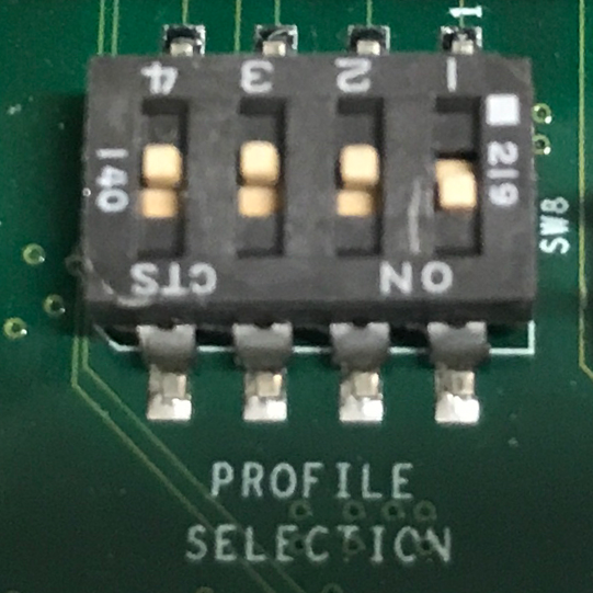
NOTE On AM335x GP EVM CAN does not work by default. The evm must have its “Profile Switch” set to 1 to enable CAN support.
Hardware/Software Changes to Enable CAN Support
AM335x General Purpose EVM
Most TI boards by default will allow the user to use CAN without any changes. The boards that do require modifications to be enabled for CAN to work will be listed below.
|
|
| enable) | disabled to okay |
Table: AM335x Hardware and Software modifications
By default the CAN signals on the AM335x GP EVM isn’t routed to the CAN connector. To do so you must configure the EVM to profile 1 instead of profile 0 which is the default. The profile switch can be found in front of the LCD screen next to the brown ribbon cable. Pictures of the EVM using profile 1 is shown above.
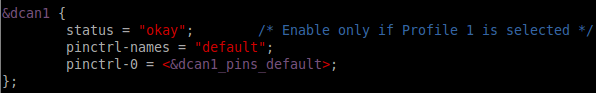
Since CAN from a hardware perspective isn’t enabled on the EVM by default it is kept disabled by default. Luckily to re-enable it is relatively simple. The user must edit the am335x-evm.dts (device tree file used for this specific evm). Edit the dcan1 node by changing the node’s status from “disabled” to “okay”. Example of this change can be seen above.
Connection Configuration
|
|
|
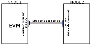
| DB9 to DB9 | Header to Header | Header to DB9 |
Table: Various DCAN EVM Connection Configuration
Equipment
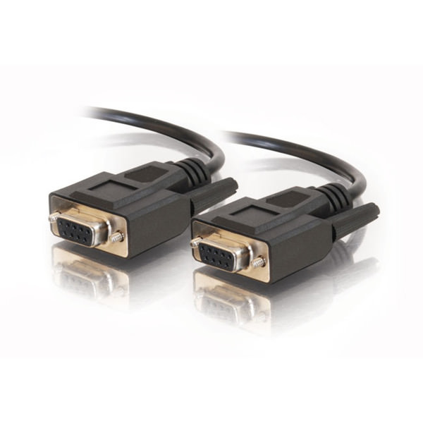
Female DB9 Cable
A male DB9 connector is used on select evms. Therefore, a female DB9/Serial Port/RS 232 cable must be used to connect with the evm. Wheather the other end of the cable is female or male will depend on if the other CAN device the user will be connecting to.
Jumper Wires
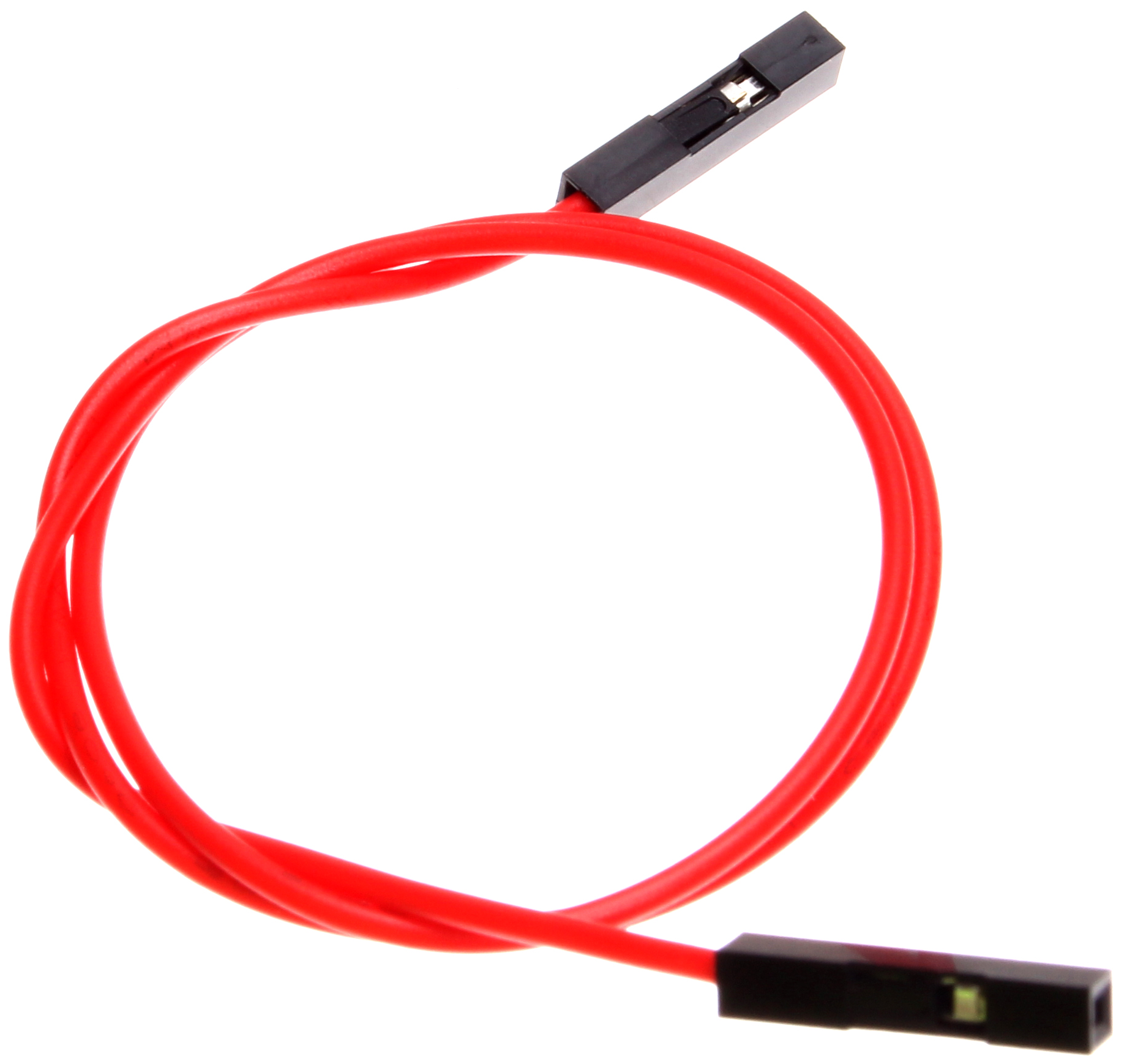
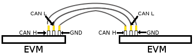
For evms whose DCAN pins are broken out via a header then a female jumper wire would be best to use to connect to the various DCAN pins on the evm. Note some evms have CAN H (typically header pin 1), GND (typically middle header) and CAN L (typically the third header). Its important to always connect the CAN’s GND pin to what other device your connecting to. Only exception are the evms that don’t include the CAN GND pin.
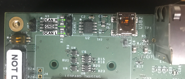
|
| Example of DCAN header on DRA72 EVM |
NOTE Its important for the user to verify which header pin is associated with the various CAN signals. Unless there are already silk screens the user may need to double check the evm’s schematic.
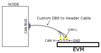
Custom DB9 to Header Cable
Typically CAN devices use a DB9 connection therefore for evms whose CAN pins are broken out via a header it is helpful to create a header to DB9 connector cable. This custom cable is simple to make. Either a male or female DB9 connector (not cable) must be purchased along with three female jumper wires.
Snip one end of each of the jumper wires and expose some of the wiring. Now solder each of the exposed wires to pin 7 (CAN H), pin 2 (CAN L) and pin 3 (GND). Make sure your soldering on the side of the DB9 that has the metal lip meant to push some of the exposed wire into and soldering to the correct pins correctly. Use the below diagram as a reference.
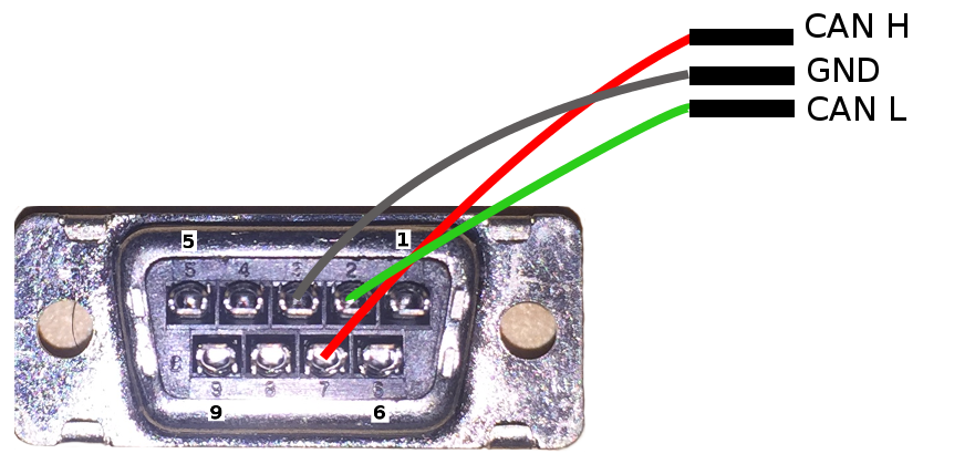
|
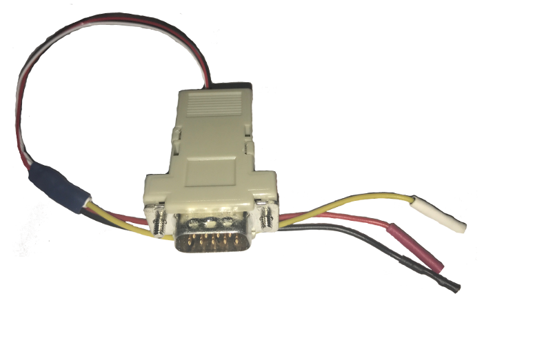
|
| Wiring Diagram | Example of completed cable. |
CAN Utilities
There may be other userspace applications that can be used to interact with the CAN bus but the SDK supports using Canutils which is already included in the sdk filesystem.
NOTE These instructions are for can0 (first and perhaps only CAN instance enabled). If the board has multiple CAN instances enabled then they can be referenced by incrementing the CAN instance number. For example 2 CAN instances will have can0 and can1.
Quick Steps
Initialize CAN Bus
- Set bit-timing
Set the bit-rate to 50Kbits/sec using the following command:
$ ip link set can0 type can bitrate 50000
- Set bit-timing (loopback mode)
Set the bit-rate to 50Kbits/sec in the loopback mode using the following command
$ ip link set can0 type can bitrate 50000 loopback on
Start CAN Bus
- Device bring up
Bring up the device using the command:
$ ip link set can0 up
NOTE The default state when starting a previously powered off CAN device is called “Error-Active”. So don’t worry when you see this command when you first start the CAN instance.
Send or Receive Packets
- Transfer packets
Packet transmission can be achieve by using cansend and cansequence utilities.
Transmit 4 bytes with standard packet id number as 0x123
$ cansend can0 123#DEADBEEF
Transmit a sequence of can frames with random IDs and random data.
$ cangen can0
- Receive packets
Packet reception can be achieve by using candump utility
$ candump can0
Stop CAN Bus
$ ip link set can0 down
Advanced Usage
The following are some examples exploring the capabilties of can-utils. See can-utils documentation for a comprehensive set of options.
Transmit fixed CAN ID and length with an incrementing data
$ cangen can0 -g 4 -I 42A -L 1 -D i -v -v
Log only error frames but no data frames
$ candump -l any,0~0,#FFFFFFFF
Statistics of CAN
Statistics of CAN device can be seen from these commands
$ ip -d -s link show can0
Below command also used to know the details
$ cat /proc/net/can/stats
Error frame details
DCAN IP Error details
If the CAN bus is not properly connected or some hardware issues DCAN has the intelligence to generate an Error interrupt and corresponding error details on hardware registers.
In CAN terminology errors are divided into three categories
- Error warning state, this state is reached if the error count of transmit or receive is more than 96.
- Error passive state, this state is reached if the core still detecting more errors and error counter reaches 127 then bus will enter into
- Bus off state, still seeing the problems then it will go to Bus off mode.
DCAN driver provides
For the above error state, driver will send the error frames to inform that there is error encountered. Frame details with respect to different states are listed here:
- Error warning frame
<0x004> [8] 00 08 00 00 00 00 60 00
ID for error warning is 0x004 [8] represents 8 bytes have received 0x08 at 2nd byte represents type of error warning. 0x08 for transmission error warning, 0x04 for receive error warning frame 0x60 at 7th byte represent tx error count.
- Error passive frame
<0x004> [8] 00 10 00 00 00 00 00 64
ID for error passive frame is 0x004 [8] represents 8 bytes have received 0x10 at 2nd byte represents type of error passive. 0x10 for receive error passive, 0x20 for transmission error passive 0x64 at 8th byte represent rx error count.
- Buss off state
<0x040> [8] 00 00 00 00 00 00 00 00
ID for bus-off state is 0x040
Error frames display with candump
candump has the capability to display the error frames along with data frames on the console. Some of the error frames details are mentioned in the previous section
$ candump can0 -e
Linux Driver Configuration
- DCAN device driver in Linux is provided as a networking driver that confirms to the socketCAN interface
- The driver is currently build-into the kernel with the right configuration items enabled (details below)
Detailed Kernel Configuration
The SoC specific kernel configuration included in the SDK by default enables full support for the DCAN driver. Therefore, manually enabling these options are not required if your using the provided kernel config (defconfig).
The below CAN specific drivers are the bare minimum needed to enable DCAN driver:
- CAN bus subsystem support
- Bosch C_CAN/D_CAN devices
- CAN_C_CAN_PLATFORM
Four additional drivers are required to utilize all the CAN features:
- Raw CAN Protocol (raw access with CAN-ID filtering)
- Broadcast Manager CAN Protocol (with content filtering)
- CAN Gateway/Router (with netlink configuration)
- CAN bit-timing calculation
[*] Networking support ->
   <*|M> CAN bus subsystem support ->
      <*|M> Raw CAN Protocol (raw access with CAN-ID filtering)
      <*|M> Broadcast Manager CAN Protocol (with content filtering)
      <*|M> CAN Gateway/Router (with netlink configuration)
         CAN Device Drivers ->
            <*|M>   Platform CAN drivers with Netlink support
            [*]     CAN bit-timing calculation
            <*|M>   Bosch C_CAN/D_CAN devices ->
               <M> Generic Platform Bus based C_CAN/D_CAN driver
NOTE *|M means can be either be built into the kernel or enabled as a kernel module.
DCAN driver Architecture
DCAN driver architecture shown in the figure below, is mainly divided into three layers Viz user space, kernel space and hardware.
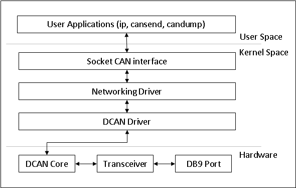
User Space
CAN utils are used as the application binaries for transfer/receive frames. These utils are very useful for debugging the driver.
Kernel Space
This layer mainly consists of the socketcan interface, network layer and DCAN driver.
Socketcan interface provides a socket interface to user space applications and which builds upon the Linux network layer. DCAN device driver for CAN controller hardware registers itself with the Linux network layer as a network device. So that CAN frames from the controller can be passed up to the network layer and on to the CAN protocol family module and vice-versa.
The protocol family module provides an API for transport protocol modules to register, so that any number of transport protocols can be loaded or unloaded dynamically.
In fact, the can core module alone does not provide any protocol and cannot be used without loading at least one additional protocol module. Multiple sockets can be opened at the same time, on different or the same protocol module and they can listen/send frames on different or the same CAN IDs.
Several sockets listening on the same interface for frames with the same CAN ID are all passed the same received matching CAN frames. An application wishing to communicate using a specific transport protocol, e.g. ISO-TP, just selects that protocol when opening the socket. Then can read and write application data byte streams, without having to deal with CAN-IDs, frames, etc.
Hardware
This layer mainly consisting of DCAN core and DCAN IO pins for packet Transmission or reception.
Driver Location
| S.No | Location | Description |
|---|---|---|
| 1 | drivers/net/can/c_can/c_can.c | DCAN driver core file |
| 2 | drivers/net/can/c_can/c_can_platform.c | Platform/SoC DCAN bus driver |