Current sensing is handled by the Programmable Real-Time Unit Industrial Communication Subsystem (PRU-ICSS). The PRU-ICSS is a co-processor subsystem containing Programmable Real-Time (PRU) cores which implements the low level firmware. The PRU-ICSS frees up the main ARM cores in the device for other functions, such as control and data processing.
SDFM
ICSS SDFM is a sigma delta interface for phase current measurement in high performance motor and servo drives. During Sigma delta decimation filtering (SDDF) the PRU hardware provides hardware integrators that do the accumulation part of Sinc filtering, while the ICSS SDFM firmware does differentiation part.
Features Supported
- 3 SDFM channels on single PRU core
- Normal Current (NC) for data read: SINC3 filter with Over-samping Ratio (OSR) 16 to 256
- Over-current (OC) for comparator: free running SINC3 filter with OSR 16 to 256
- Event generation(ARM interrupt for data read from DMEM, GPIO toggle for high and low thresholds)
- Single level High and Low threshold comparator
- Trigger based normal current sampling
- Continuous normal current sampling
- Double update: Double normal current sampling per EPWM cycle
- SDFM Sync with EPWM
- Fast detect
- PWM Trip generation for overcurrent
- Clock Phase Compensation
- Zero cross comparator
Features Not Supported
System Design Considerations
Over Sample Ratio
- OSR Below 16 at SD_CLK greater than 20MHz. The normal current task takes 300ns to 400ns to complete and its execution is based on CMP event and task manager. When we configure OSR below 16 for greater than 20 MHz SD clock, the NC will not be able to complete its processing until the next sample is ready, this will cause the NC samples to be inaccurate.
PWM TripZone (TZ) Block Inputs and Outputs
- Fixed mapping between the fast detect errors and PWM TZ blocks
- Axis 1 (Channel0 - Channel2) mapped with PWM0
- Axis 2 (Channel3 - Channel5) mapped with PWM1
- Axis 3 (Channel6 - Channel8) mapped with PWM2
- PWM1 and PWM2 TZ output pins are only valiable on am243x-lp in servo BP signal mode
SDFM Data Pin Conflicts on AM243x LaunchPad(LP)
- In default signal mode, all 9 SD data pins are available on LP jumpers. But in servo BP signal mode the routing for 4 SD data pins (SD4_D, SD5_D, SD6_D and SD7_D) is changing. Out of the 4 pins, two pins are available on board jumpers (sd4_d and sd5_d) and two are not available (sd6_d and sd7_d9). For more details on pinmux with LP, please see AM243x LaunchPad Development Kit User's Guide
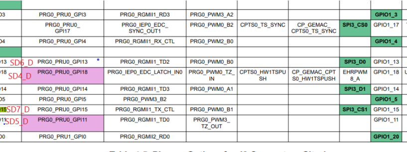
PIN routing for SD channels
Datasheet
Fast Detect Latency
- Fast Detect block starts comparison after the first 32 sample clocks.
- Latency measured for the 20MHz sigma delta clock is 1.632us.
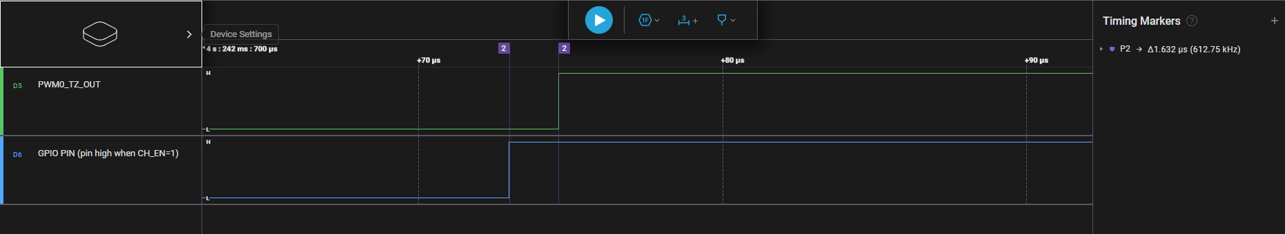
FD latency
Task Time for Normal Current at 300MHz PRU Core Clk
Normal current processing time for its different execution flows
- Task time when only single update is enabled
- 320ns, without R5 interrupt and samples store in TCM memory
- 328ns, With R5 intruppt and smaples store in TCM memory
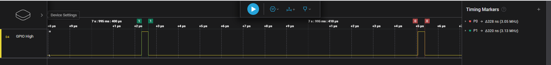
NC Task time for single update
- Task time when double update is enabled
- 320ns, without R5 interrupt and samples store in TCM memory
- 336ns, With R5 intruppt and smaples store in TCM memory.
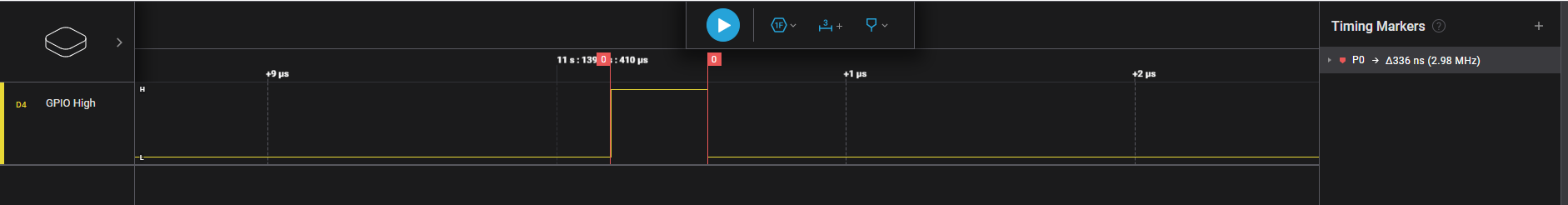
NC Task time for double update
- Task time for continuous mode is 360ns
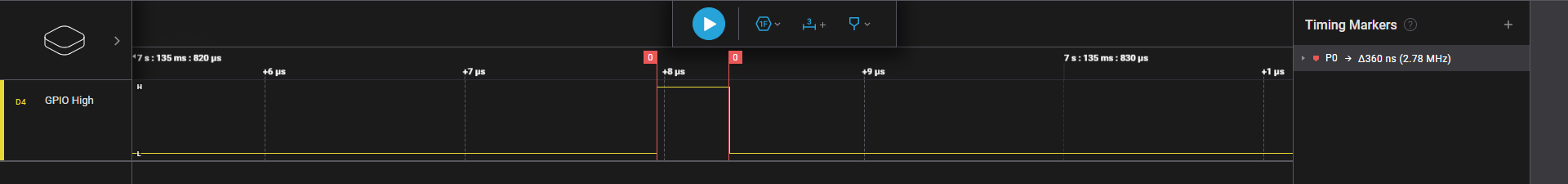
NC Task time for continuous mode
- Worst case Normal current task time = 360ns + 3-4 pru cycles time(Task switch, task exit & scratch pas switch)
ICSS SDFM Design
SDFM Interface Design explains the design in detail.
Example
ICSS SDFM Examples
API
APIs for SDFM


 1.8.20