|
AM243x Motor Control SDK
09.01.00
|


|
|
AM243x Motor Control SDK
09.01.00
|
|
This example does continuous normal current sampling. Normal current over-samping Ratio (OSR) can be configured by the user. There are two different examples based on number of SDFM channels.
Only one core - PRU is used for this example.
The example does the below
Load share mode of PRU-ICSSG is enabled for this example and three cores - RTU-PRU, PRU and TX-PRU are used for this example.
The example does the below
| Folder/Files | Description |
|---|---|
| ${SDK_INSTALL_PATH}/examples/current_sense/icss_sdfm_nine_channel_with_continuous_mode | Application specific sources for ICSS SDFM for continuous normal current sampling for nine channels |
| ${SDK_INSTALL_PATH}/examples/current_sense/icss_sdfm_three_channel_with_continuous_mode | Application specific sources for ICSS SDFM for continuous normal current sampling for three channels |
| ${SDK_INSTALL_PATH}/examples/current_sense | Common source for ICSS SDFM applications |
| ${SDK_INSTALL_PATH}/source/current_sense/sdfm | |
| firmware/ | Folder containing ICSS SDFM firmware sources |
| driver/ | ICSS SDFM driver source |
| include/ | Folder containing ICSS SDFM structures and APIs declarations |
| Parameter | Value |
|---|---|
| CPU + OS | r5fss0-0 freertos |
| ICSSG | ICSSG0 |
| PRU | PRU0 (single channel) |
| PRU0, RTU-PRU0, TXPRU0 (multi channel using three PRUs - load share mode) | |
| Toolchain | ti-arm-clang |
| Board | am243x-evm, am243x-lp |
| Examples folder | examples/current_sense |
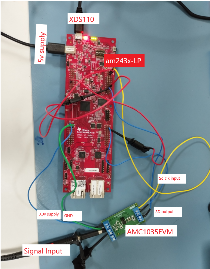
Other than the basic EVM setup mentioned in EVM Setup , below additional hardware is required to run this demo


| Test Details | Steps | Pass/Fail Criteria |
|---|---|---|
| 1. Normal current sample data | 1. Run example on supported board | The drawn graph and raw data should look like the attached image |
| 2. Draw the graph of sdfm_ch0_samples, sdfm_ch1_samples and sdfm_ch2_samples arrays | 
NNCC sample data | |
| 2. To check Normal Current (NC) Samples with Different NC OSR Values | 1. Set NC OSR values between 16 to 255 | Raw data should have different resolution for different OSR values |
| 2. Build and run example | ||
| 3. Observe resolution of raw data | ||
| 3. To check NC samples with different sdfm clock values | 1. Set NC OSR to 64 | Raw data should have different resolution for different sdfm clock values |
| 2. Set ecap_divider variable in sdfm.c file for different sd clock generation | ||
| 3. Set Sigma delta clock equal to ecap generated clock | ||
| 4. Build and run example | ||
| 5. Observe resolution of raw data | ||
| 4. To check Fast detect | 1. Set NC OSR to 64 | Trip must be triggered for the respective pwm trip zone block |
| 2. Enable Fast detect | ||
| 3. Set Fast Detect fields with these values { window size = 4, Zero max = 18, Zero min = 2} | Zero max/min Threshold hit bits must be constantly unset and set | |
| 4. Build and run example | One max/min threshold hit bits must be unset | |
| 5. 1) Observe TZ_OUT PIN. 2) Check zero/one count max & zero/one count min threshold hit bits in memory map | ||
| 5.Testing with sdfm clock from EPWM | 1. Make hardware set up like attached image | All test cases results should match with ECAP test case results |
2. 
SDFM: Hw set for clock from EPWM | ||
| 3. Enable "APP_EPWM1_ENABLE" macro in app_sdfm.c file | ||
| 4. Set EPWM1 out put frequency to 12.5MHz or 5MHz in app_sdfm.c file | ||
| 5. Set Sigma delta clock equal to EPWM1 output frequency | ||
| 6. Build and run example | ||
| 7. Test all tese cases from 1 to 5 with EPWM clock |
 1.8.20