|
AM243x Motor Control SDK
09.01.00
|


|
|
AM243x Motor Control SDK
09.01.00
|
|
This example does trigger based normal current sampling. Normal current Over-samping Ratio (OSR), Over current OSR and Normal current trigger time can be configured by the user. There are two different examples based on number of SDFM channels.
Only one core - PRU is used for this example.
The example does the below:
Load share mode of PRU-ICSSG is enabled for this example and three cores - RTU-PRU, PRU and TX-PRU are used for this example.
The example does the below
| Folder/Files | Description |
|---|---|
| ${SDK_INSTALL_PATH}/examples/current_sense/icss_sdfm_nine_channel_load_share_mode | Application specific sources for ICSS SDFM for trigger based normal current sampling for nine channels |
| ${SDK_INSTALL_PATH}/examples/current_sense/icss_sdfm_three_channel_single_pru_mode | Application specific sources for ICSS SDFM for trigger based normal current sampling for three channels |
| ${SDK_INSTALL_PATH}/examples/current_sense | Common source for ICSS SDFM applications |
| ${SDK_INSTALL_PATH}/source/current_sense/sdfm | |
| firmware/ | Folder containing ICSS SDFM firmware sources |
| driver/ | ICSS SDFM driver source |
| include/ | Folder containing ICSS SDFM structures and APIs declarations |
| Parameter | Value |
|---|---|
| CPU + OS | r5fss0-0 freertos |
| ICSSG | ICSSG0 |
| PRU | PRU0 (single channel) |
| PRU0, RTU-PRU0, TXPRU0 (multi channel using three PRUs - load share mode) | |
| Toolchain | ti-arm-clang |
| Board | am243x-evm, am243x-lp |
| Examples folder | examples/current_sense |
Other than the basic EVM setup mentioned in EVM Setup , below additional hardware is required to run this demo


| Test Details | Steps | Pass/Fail Criteria |
|---|---|---|
| 1. Normal current sample data | 1. Run example on supported board | The drawn graph and raw data should look like the attached image |
| 2. Draw the graph of sdfm_ch0_samples, sdfm_ch1_samples and sdfm_ch2_samples arrays | 
NC sample data | |
| 2. To check raw data for Single Update (64 Normal Current (NC) OSR) | 1. Set NC OSR to 64 | The drawn graph and raw data should look like the attached image |
| 2. Set single update trigger time to half of EPWM cycle time | ||
| 3. Disable double update | ||
| 3. Build and run example | ||
| 4. Draw graph for Raw data | 
Single Update Raw data | |
| 3. To check Raw data for Double Update | 1. Set NC OSR to 64 | The drawn graphs and raw data should look like attached image |
| 2. Enable double update | ||
| 3. Set single update trigger time to 1/4 of EPWM cycle time | ||
| 4. Set double update trigger time to 3/4 of EPWM cycle time | ||
| 5. Build and run example | ||
| 6. Draw graph for Raw data | 
Double Update Raw data | |
The pattern of the graph should be different from the single update graph. It takes 2 samples in one EPWM cycle so the graph pattern should look more like a sine wave compare to single update graph | ||
| 4. To check Threshold comparator and Over current | 1. Set High Threshold to 3500 and low threshold to 2500 | Trip status bit must be set for the respective pwm trip zone block and TZ_OUT pin must be high |
| 2. Set Over current OSR to 16 | High Low Threshold status bits must be constantly unset and set | |
| 3. Probe PWMm_TZ_OUT pin | ||
| 4. Build and run example | ||
| 5. Capture signal in Logic analyzer | ||
| 5. To check NC Samples with Different NC OSR Values | 1. Set NC OSR values between 16 to 255 | Raw data should have different resolution for different OSR values |
| 2. Build and run example | ||
| 3. Observe resolution of raw data | ||
| 6. To check NC samples with different sdfm clock values | 1. Set NC OSR to 64 | Raw data should have different resolution for different sdfm clock values |
| 2. Set ecap_divider variable in sdfm.c file for different sd clock generation | ||
| 3. Set Sigma delta clock equal to ecap generated clock | ||
| 4. Build and run example | ||
| 5. Observe resolution of raw data | ||
| 7. To check Fast detect | 1. Set NC OSR to 64 | Trip must be triggered for the respective pwm trip zone block |
| 2. Enable Fast detect | ||
| 3. Set Fast Detect fields with these values { window size = 4, Zero max = 18, Zero min = 2} | Zero max/min Threshold hit bits must be constantly unset and set | |
| 4. Build and run example | One max/min threshold hit bits must be unset | |
| 5. 1) Observe TZ_OUT PIN. 2) Check zero/one count max & zero/one count min threshold hit bits in memory map | ||
| 8. To check Zero Cross | 1. Set Overcurrent (OC) OSR to 16 | Logic analyzer capture should match with this capture |
| 2. Enable Zero cross detection | ||
| 3. Set zero cross threshold vales to 1700 {value should be between max sampled value and min sampled value for 16 OSR} | 
Zero cross GPIO behaviour | |
| 4. probe ch0 zero cross GPIO pins and input SD analog signal | ||
| 5. Build and run example | ||
| 6. Capture signals in logic analyzer | ||
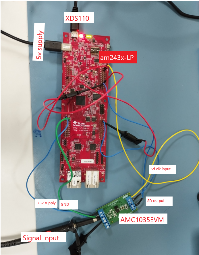
| 9.Testing with sdfm clock from EPWM | 1. Make hardware set up like attached image | All test cases results should match with ECAP test case results |
2. 
SDFM: Hw set for clock from EPWM | ||
| 3. Enable "APP_EPWM1_ENABLE" macro in app_sdfm.c file | ||
| 4. Set EPWM1 out put frequency to 12.5MHz or 5MHz in app_sdfm.c file | ||
| 5. Set Sigma delta clock equal to EPWM1 output frequency | ||
| 6. Build and run example | ||
| 7. Test all tese cases from 1 to 5 with EPWM clock |
 1.8.20