Configuration
The configuration panel provides options to specify the values of several Ultrasonic Sensing Library parameters, then communicate those values to the target.
Each parameter has a defined range to ensure that the values are in line with the library’s specifications. Attempts to change the fields to a value outside the range will be reverted back to the previous value.
HW Meter Configuration
The Meter hardware configuration enables selection of the board, MSP430 device and execution mode (as shown below). It can be accessed in the GUI via the Options->Meter Options (Alt + O).
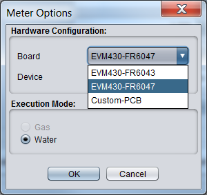
Fig. 5 Meter Options
Currently there are 3 boards supported. The devices supported for each board are described below:
- EVM430-FR6043 - defaults device MSP430FR6043
- EVM430-FR6047 - defaults device MSP430FR6047
- Custom-PCB - allows the user to select a device from the supported devices
Supported Devices
| Device | Execution Mode |
|---|---|
| MSP430FR5041 | Gas or Water |
| MSP430FR5043 | Gas or Water |
| MSP430FR50431 | Gas or Water |
| MSP430FR6041 | Gas or Water |
| MSP430FR6043 | Gas or Water |
| MSP430FR60431 | Gas or Water |
| MSP430FR6045 | Water |
| MSP430FR6047 | Water |
| MSP430FR60471 | Water |
Connecting
If not already connected to the target, connect via either the Communications - Connect dropdown, or press F1. The connection status at the bottom left corner of the GUI should display the current connection target and platform.
Water Meter Configuration
This section covers the hardware and parameter configuration for water mode.
Parameters Configuration
Selecting Parameters
Change between general parameters and advanced parameters by clicking on the respective tab at the top of the configuration panel.

Fig. 6 Parameter Options
The complete range of parameters, a description, and their ranges is shown below.
| GUI Parameter | Description | Default | Water Min | Water Max |
|---|---|---|---|---|
| F1 | Pulse Output Frequency 1 | 1000 | 772 | 2,500 |
| F2 | Pulse Output Frequency 2 (not used for water metering) | 1,000 | N/A | N/A |
| Gap between Pulse Start and ADC Capture (us) | Time in microseconds from PPG pulse to ADC start | 60 | 3 | 9,000 |
| Number of Pulses | Number of excitation pulses | 25 | 0 | 63 |
| UPS and DNS Gap (us) | Time between ADC captures in a sequence in microseconds | 3,000 | 100 | 16,000 |
| UPS0 and UPS1 Gap (ms) | Time between ADC captures in a single channel in milliseconds | 1,000 | 20 | 2,000 |
| GUI Based Gain Control 1 | PGA gain value to apply to register | 1.0 db | -6.5 db | 30.8 db |
| Meter Constant | Volume scale factor - varies by meter, must be calculated | 12,742,000 | 0 | 22,742,000 |
| Units | Select units to be in Liters per Hour (l/h) or Gallons per Minute (G/m) | l/h | - | - |
| Volume Flow Rate Calibration Ranges | Number of volume flow rate calibration ranges | 1 | 1 | 16 |
| USSXT (kHz) | External crystal frequency in kHz | 8,000 | 4,000 | 8,000 |
| ADC Sampling Frequency | N/A | N/A | N/A | N/A |
| Signal Sampling Frequency (kHz) 1 | Signal Sampling Frequency in kHz | 4,000 | 425 | 8,000 |
| ADC Over Sampling 1 | Over-sampling rate of the ADC | 20 | 10 | 160 |
| Delta TOF Offset (ps) | Amount to offset the Delta Time of Flight in picoseconds | 0 | -10,000 | 10,000 |
| Abs TOF Additional Delay (ns) | Amount to offset the Absolute Time of Flight in nanoseconds | 0 | -1,000,000 | 1,000,000 |
| Capture Duration (us) | Duration of samples in microseconds | 40 | 1 | 100 |
| Interpolation Correction Table Size 2 | Interpolation Correction Table Size used for Lobe Algorithm | 256 | Disabled | 1024 |
| Algorithm Option | Algorithm Option | Lobe | Lobe | Lobe |
| ULP Bias Delay | Delay Bias | 3 | 0 | 3 |
| Start PPG Count (ns) | Time to start the PPG pulse trigger in nanoseconds | 10,000 | -2,000,000,000 | 2,000,000,000 |
| Turn on ADC Count (ns) | Time to turn on the ADC in nanoseconds | 5,000 | -2,000,000,000 | 2,000,000,000 |
| Start PGA and IN Bias Count (ns) | Time to turn the PGA and Input Biasing on | 0 | -2,000,000,000 | 2,000,000,000 |
| User Param #6 | N/A | 0 | -2,000,000,000 | 2,000,000,000 |
| USS XTAL Settling Count (us) | External Crystal settling time in microseconds | 120 | 120 (ceramic resonators), 5000 (crystals) | 120 (ceramic resonators), 5000 (crystals) |
| Envelope Crossing Threshold | Envelope crossing threshold | 11 | 1 | 100 |
| Search Range | AbsTOF Search Range | 3 | 0 | Min = (Signal Sampling Freq. / Transducer Freq.) Max = Min x Number of pulses |
| User Param #10 | N/A | 0 | -2,000,000,000 | 2,000,000,000 |
link.
Code Generation
This section explains how each #define in the USS_userConfig.h are generated by Design Center. For each row in the table below, parameters in the first column are referenced in the Water Code Generation column as (P1,P2,…). The advanced parameters in the second column are referenced in the Water Code Generation column as (AP1,AP2,…).
| Parameter Name (P1,P2...) | Advanced Parameter Name (AP1,AP2...) | #define Tag | Water Code Generation |
|---|---|---|---|
| F1 | USS_F1_FREQ | P1 * 1000 | |
| F2 | USS_F2_FREQ | 0 | |
| Pulse Mode | USS_PULSE_MODE | if P1 = Single Tone USS_PULSE_MODE_SINGLE_TONE if P1 = Dual Tone USS_PULSE_MODE_DUAL_TONE if P1 = F1 to F2 Sweep USS_PULSE_MODE_MULTI_TONE |
|
| Gap between pulse start and ADC capture (us) | Start PPG Count (ns) | USS_ADC_SAMP_COUNT_SEC | (P1 /106)+ (AP1 /109) |
| Number of Pulses | USS_NUM_OF_EXCITATION_PULSES_F1 | P1 | |
| Number of Pulses, Pulse Mode | USS_NUM_OF_EXCITATION_PULSES_F2 | 0 | |
| Number of Pulses,Pulse Mode | USS_NUM_OF_TRILL_PULSES | 0 | |
| UPS and DNS Gap (us) | USS_RESTART_CAP_COUNT_SEC | P1 /106 | |
| UPS0 and UPS1 Gap (ms) | USS_SYS_MEASUREMENT_PERIOD | P1*32768/103 | |
| GUI Based Gain Control | USS_GAIN_RANGE | if P1 >= 0 (e.g. X.Y db) USS_Capture_Gain_Range_X_Y if P1 < 0 (e.g. -X.Y db) USS_Capture_Gain_Range_minus_X_Y |
|
| Meter Constant | USS_VOLUME_SCALE_FACTOR | P1 | |
| USSXT (kHz) 1 | USS_PLL_XTAL_IN_KHZ | if P1 = 4000 USS_HSPLL_input_clock_freq_4_KHz if P1 = 8000 USS_HSPLL_input_clock_freq_8_KHz |
|
| Signal Sampling Frequency (kHz), ADC Over Sampling Rate | USS_HSPLL_FREQ_IN_MHZ | AP1 * AP2 / 103 | |
| ADC Over Sampling Rate | USS_OVER_SAMPLE_RATE | AP1 | |
| Delta TOF Offset (ps) | USS_ALG_DCOFFSET | AP1 / 1012 | |
| Abs TOF Additional Delay (ns) | USS_ALG_ADC_ADDITIONAL_CAP_DLY | AP1 / 109 | |
| Capture Duration (us) | USS_CAPTURE_DURATION_USEC | AP1 | |
| Interpolation Correction Table Size | USS_ENABLE_ABSTOF_LOBE_OFFSET_CORRECTION | if AP1 = Disabled false else true |
|
| Algorithm Option | USS_ALG_ABS_TOF_COMPUTATION_MODE | USS_ALG_ABS_TOF_COMPUTATION_MODE_<AP1> (in capital letters e.g. Lobe = LOBE) | |
| ULP Bias Delay, Start PGA and IN Bias Count (ns) | USS_ULP_BIAS_DELAY |
ifAP1 = 1 USS_measurement_ULP_bias_delay_100_usec else if AP1 = 2 USS_measurement_ULP_bias_delay_200_usec else if AP1 = 3 USS_measurement_ULP_bias_delay_300_usec else USS_measurement_ULP_bias_delay_no_delay | |
| Start PPG Count (ns) | USS_START_CAPTURE_SEC | AP1 / 109 | |
| Turn On ADC Count (ns) | USS_TURN_ON_ADC_COUNT_SEC | AP1 / 109 | |
| Start PGA and IN Bias Count (ns) | USS_PGA_IN_BIAS_COUNT_SEC | AP1 / 109 | |
| USS XTAL Settling Count (us) | USS_HSPLL_USSXTAL_SETTLING_USEC | AP1 | |
| Envelope Crossing Threshold | USS_ALG_ABS_TOF_HILB_CROSS_THRESHOLD | AP1 / 100 | |
| Envelope Crossing Threshold | USS_ALG_RATIO_OF_TRACK_LOBE | AP1 / 100 | |
| Search Range | USS_ALG_ABS_TOF_SEARCH_RANGE | AP1 | |
| USS_MEASUREMENT_TURN_ON_EXTERNAL_AMP_SEC | 0 | ||
| USS_ALG_VOLUME_RATE_COMPUTATION_MODE | USS_ALG_VOLUME_RATE_COMPUTATION_OPTION_GENERIC | ||
| USS_ENABLE_VFR_METER_CALIB | if "Waveform Tab -> Adv Calibration Table" is selected true else false |
Gas Meter Configuration
This section covers the hardware and parameter configuration for gas mode.
Parameters Configuration
Selecting Parameters
Change between general parameters and advanced parameters by clicking on the respective tab at the top of the configuration panel.
Fig. 7 Parameter Options
The complete range of parameters, a description, and their ranges is shown below.
| GUI Parameter | Description | Default | Gas Min | Gas Max |
|---|---|---|---|---|
| F1 | Pulse Output Frequency 1 | 170 | 80 | 550 |
| F2 | Pulse Output Frequency 2 | 240 | 80 | 630 |
| Gap between Pulse Start and ADC Capture (us) | Time in microseconds from PPG pulse to ADC start | 170 | 0 | 16,383 |
| Number of Pulses | Number of excitation pulses | 24 | 0 | 60 |
| UPS and DNS Gap (us) | Time between ADC captures in a sequence in microseconds | 8,000 | 0 | 16,384 |
| UPS0 and UPS1 Gap (ms) | Time between ADC captures in a single channel in milliseconds | 150 | 0 | 16,384 |
| GUI Based Gain Control 1 | PGA gain value to apply to register | 1.0 db | -6.5 db | 30.8 db |
| Meter Constant | Volume scale factor - varies by meter, must be calculated | 61 | 0 | 22,742,000 |
| Units | Select units to be in Liters per Hour (l/h) or Gallons per Minute (G/m) | l/h | - | - |
| Volume Flow Rate Calibration Ranges | Number of volume flow rate calibration ranges | 1 | 1 | 16 |
| USSXT (kHz) 1 | External crystal frequency in kHz | 8,000 | 4,000 | 8,000 |
| ADC Sampling Frequency | N/A | N/A | N/A | N/A |
| Signal Sampling Frequency (kHz) 1 | Signal Sampling Frequency in kHz | 1,000 | 425 | 8,000 |
| ADC Over Sampling 1 | Over-sampling rate of the ADC | 80 | 10 | 160 |
| Delta TOF Offset (ps) | Amount to offset the Delta Time of Flight in picoseconds | 0 | -10,000 | 10,000 |
| Abs TOF Additional Delay (ns) | Amount to offset the Absolute Time of Flight in nanoseconds | 0 | -1,000,000 | 1,000,000 |
| Capture Duration (us) | Duration of samples in microseconds | 300 | 0 | 100,000 |
| Interpolation Correction Table Size | Interpolation Correction Table Size used for Lobe Algorithm | Disabled | N/A | N/A |
| Algorithm Option | Algorithm Option | 3 | 3 (Hilbert Wide) | 3 (Hilbert Wide) |
| Envelope Crossing Threshold | Envelope crossing threshold | 50 | 1 | 100 |
| Start PPG Count (ns) | Time to start the PPG pulse trigger in nanoseconds | 200,000 | -2,000,000,000 | 2,000,000,000 |
| Turn on ADC Count (ns) | Time to turn on the ADC in nanoseconds | 20,000 | -2,000,000,000 | 2,000,000,000 |
| Start PGA and IN Bias Count (ns) | Time to turn the PGA and Input Biasing on | 200,000 | -2,000,000,000 | 2,000,000,000 |
| USS XTAL Settling Count (us) | External Crystal settling time in microseconds | 120 | -2,000,000,000 | 2,000,000,000 |
| External Amplifier Count (ns) | External Amplifier Count in nanoseconds | 10,000 | -2,000,000,000 | 2,000,000,000 |
| User Param #8 | 128 = Disables Additional Trill Pulses 384 = Enables Additional Trill Pulses Other values = Reserved |
384 | 128 | 384 |
| Search Range | AbsTOF Search Range | 8 | 0 | Min = (Signal Sampling Freq. / Transducer Freq.) Max = Min x Number of pulses |
| User Param #10 | N/A | 0 | -2,000,000,000 | 2,000,000,000 |
Code Generation
This section explains how each #define in the USS_userConfig.h are generated by Design Center. For each row in the table below, parameters in the first column are referenced in the Water Code Generation column as (P1,P2,…). The advanced parameters in the second column are referenced in the Water Code Generation column as (AP1,AP2,…).
| Parameter Name (P1,P2...) | Advanced Parameter Name (AP1,AP2...) | #define Tag | Gas Code Generation |
|---|---|---|---|
| F1 | USS_F1_FREQ | P1 * 1000 | |
| F2 | USS_F2_FREQ | P1 * 1000 | |
| Pulse Mode | USS_PULSE_MODE | if P1 = Single Tone USS_PULSE_MODE_SINGLE_TONE if P1 = Dual Tone USS_PULSE_MODE_DUAL_TONE if P1 = F1 to F2 Sweep USS_PULSE_MODE_MULTI_TONE |
|
| Gap between pulse start and ADC capture (us) | Start PPG Count (ns) | USS_ADC_SAMP_COUNT_SEC | (P1 /106)+ (AP1 /109) |
| Number of Pulses | USS_NUM_OF_EXCITATION_PULSES_F1 | P1 | |
| Number of Pulses, Pulse Mode | USS_NUM_OF_EXCITATION_PULSES_F2 | if (P2 = Single Tone) or (P2 = F1 to F2 Sweep) 0 if P2 = Dual Tone P1 |
|
| Number of Pulses,Pulse Mode | USS_NUM_OF_TRILL_PULSES | if (P2 = Single Tone) or (P2 = Dual Tone) 0 if P2 = F1 to F2 Sweep P1 / 2 |
|
| UPS and DNS Gap (us) | USS_RESTART_CAP_COUNT_SEC | P1 /106 | |
| UPS0 and UPS1 Gap (ms) | USS_SYS_MEASUREMENT_PERIOD | P1*32768/103 | |
| GUI Based Gain Control | USS_GAIN_RANGE | if P1 >= 0 (e.g. X.Y db) USS_Capture_Gain_Range_X_Y if P1 < 0 (e.g. -X.Y db) USS_Capture_Gain_Range_minus_X_Y |
|
| Meter Constant | USS_VOLUME_SCALE_FACTOR | P1 | |
| USSXT (kHz) 1 | USS_PLL_XTAL_IN_KHZ | if P1 = 4000 USS_HSPLL_input_clock_freq_4_KHz if P1 = 8000 USS_HSPLL_input_clock_freq_8_KHz |
|
| Signal Sampling Frequency (kHz), ADC Over Sampling Rate | USS_HSPLL_FREQ_IN_MHZ | AP1 * AP2 / 103 | |
| ADC Over Sampling Rate | USS_OVER_SAMPLE_RATE | AP1 | |
| Delta TOF Offset (ps) | USS_ALG_DCOFFSET | AP1 / 1012 | |
| Abs TOF Additional Delay (ns) | USS_ALG_ADC_ADDITIONAL_CAP_DLY | AP1 / 109 | |
| Capture Duration (us) | USS_CAPTURE_DURATION_USEC | AP1 | |
| Interpolation Correction Table Size | USS_ENABLE_ABSTOF_LOBE_OFFSET_CORRECTION | if AP1 = Disabled false else true |
|
| Algorithm Option | USS_ALG_ABS_TOF_COMPUTATION_MODE | USS_ALG_ABS_TOF_COMPUTATION_MODE_<AP1> (in capital letters e.g. Lobe = LOBE) | |
| Start PGA and IN Bias Count (ns) | USS_ULP_BIAS_DELAY |
ifAP1 = 0 USS_measurement_ULP_bias_delay_200_usec else USS_measurement_ULP_bias_delay_no_delay | |
| Start PPG Count (ns) | USS_START_CAPTURE_SEC | AP1 / 109 | |
| Turn On ADC Count (ns) | USS_TURN_ON_ADC_COUNT_SEC | AP1 / 109 | |
| Start PGA and IN Bias Count (ns) | USS_PGA_IN_BIAS_COUNT_SEC | AP1 / 109 | |
| USS XTAL Settling Count (us) | USS_HSPLL_USSXTAL_SETTLING_USEC | AP1 | |
| Envelope Crossing Threshold | USS_ALG_ABS_TOF_HILB_CROSS_THRESHOLD | AP1 / 100 | |
| Envelope Crossing Threshold | USS_ALG_RATIO_OF_TRACK_LOBE | 0.5 | |
| Search Range | USS_ALG_ABS_TOF_SEARCH_RANGE | AP1 | |
| External Amplifier Count | USS_MEASUREMENT_TURN_ON_EXTERNAL_AMP_SEC | AP1 / 109 | |
| USS_ALG_VOLUME_RATE_COMPUTATION_MODE | USS_ALG_VOLUME_RATE_COMPUTATION_OPTION_GAS | ||
| USS_ENABLE_VFR_METER_CALIB | if "Waveform Tab -> Adv Calibration Table" is selected true else false |
Parameter vs Demo Application
This sections includes how each parameter impacts software modules and the supported algorithms in the demo application.
| Parameter Name | Advanced Parameter Name |
Software Modules | Algorithms (Lobe=A1, Hilbert=A2, Lobe-Wide=A3,Hilbert-Wide=A4) |
|||||
|---|---|---|---|---|---|---|---|---|
| HW | LIB | APP | A1 | A2 | A3 | A4 | ||
| F1 | ✔ | ✔ | ||||||
| F2 | ✔ | ✔ | ||||||
| Pulse Mode | ✔ | ✔ | ✔ | ✔ | ||||
| Gap between pulse start and ADC Capture | ✔ | ✔ | ||||||
| Number of Pulses | ✔ | ✔ | ||||||
| UPS and DNS Gap (us) | ✔ | |||||||
| UPS0 to UPS1 Gap (ms) | ✔ | |||||||
| GUI Based Gain Control | ✔ | |||||||
| Meter Constant | ✔ | |||||||
| Volume Flow Rate Calibration Ranges | ✔ | |||||||
| USSXT (kHz) | ✔ | |||||||
| ADC Sampling Frequency (kHz) | ||||||||
| Signal Sampling Frequency (kHz) | ✔ | ✔ | ||||||
| ADC Over Sampling Rate | ✔ | ✔ | ||||||
| Delta TOF Offset (ps) | ✔ | |||||||
| Abs TOF Additional Delay (ns) | ✔ | |||||||
| Capture Duration (us) | ✔ | ✔ | ||||||
| Interpolation Correction Table Size | ✔ | ✔ | ||||||
| Algorithm Option | ✔ | ✔ | ✔ | ✔ | ✔ | |||
| ULP Bias Delay (water only) | ✔ | |||||||
| Start PPG Count (ns) | ✔ | |||||||
| Turn on ADC Count (ns) | ✔ | |||||||
| Start PGA and IN Bias Count (ns) | ✔ | |||||||
| USS XTAL Settling Count (us) | ✔ | |||||||
| Envelope Crossing Threshold | ✔ | ✔ | ✔ | |||||
| Search Range | ✔ | ✔ | ✔ | ✔ | ||||
| External Amplifier (ns) (gas only) | ✔ | |||||||
Updating the Target

Fig. 8 Configuration Options
Requesting an update
After changing configuration, update the target by clicking “Request Update”. This sets each enabled parameter on the target to the currently selected GUI value. A popup box will appear at the end of the transmission indicating either a successful or unsuccessful update.
If the update was unsuccessful, please validate that the current parameter range is correct and check the error tab if present; the error tab will always appear if an error is reported from the target.
Common reasons for a configuration to be rejected are that it would produce very low signal strength, an incorrect transmission frequency, or that it would produce an incorrect base algorithm configuration (incorrect settling time, etc).
Saving Configurations
Save the current configuration (values of each parameter) or load saved configurations by using the “Save Configuration” or “Load Configuration” buttons. The location of the configuration file will default to a USS directory created in your home folder upon installation, at ~home/USS_VERSION/USSWorkspace/USS_Project/config. Saving the configuration will also save the automatic logging state and location. Additionally, the GUI will automatically save the configuration upon exit and reload the exit configuration when launched.
Reset the configuration
Clicking the “Reset Values” button will reset all parameters to the default install values for that meter mode.
Header File Generation
USS GUI 1.70+ supports generation of header files for USS-enabled devices. The location for these header files (USS_userConfig.h, USS_meterVFRCalib.h and USS_intrplCorrLUT.h) will default to a USS directory created in your home folder upon installation, at ~home/USS_VERSION/USSWorkspace/USS_Project/headers. The header files will be generated with the appropriate parameters contained in the current GUI configuration filled out for use importing to the user application. This allows for easy configuration of IDE projects with the same configurations used when tuning in the GUI.
Note The parameters shown below from the Parameter Configuration require the user to regenerate the header file and recompile the code:
- Pulse Mode (Single Tone, Dual Tone, …)
- Volume Flow Rate Calibration Ranges
- USSXT (kHz)
- Interpolation Correction Table Size
- Algorithm Option
User Parameters
The USS Design Center provides six user-reserved parameters on the GUI. These allow the user to implement a target-side handler for these commands and integrate their own configuration options to be controlled from the Design Center.
More information on the structure of the HID packets exists in the USS Software Library documentation set.
Timing Diagram
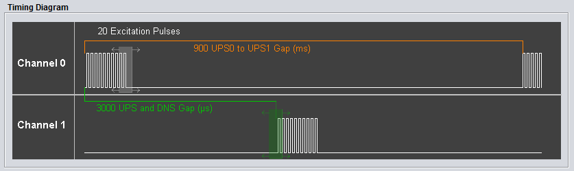
Fig. 9 Interactive Timing Diagram
The interactive timing diagram provides a way to visualize the number of excitation pulses, UPS0 to UPS1 gap, and UPS and DNS gap. Additionally, users can configure the number of pulses and UPS and DNS gap by clicking and dragging the white (pulses) and green (UPS and DNS gap) boxes to the left or right to increase or decrease the current value.
Currently, the USS library implementation does not reflect the timing diagram perfectly. The current library implementation has the UPS0 to UPS1 gap implemented as the end of the last excitation pulse in Channel 1 to the beginning of the next excitation pulse series in Channel 0. Future implementations of the USS library will match the displayed timing diagram, where the UPS0 to UPS1 gap is from the beginning of an excitation series to the beginning of the next excitation series in the same channel.
More Information
- For more information on the application, and available evaluation kits, see the download page.
- For technical support, email the USS GUI support team or visit the MSP430 E2E forum