Configuration
The configuration panel provides options to specify the values of a range of Ultrasonic Sensing Library parameters, then communicate those values to the target.
Each parameter has a defined range to ensure that the values are in line with the library’s specifications. Attempts to change the fields to a value outside the range will be reverted back to the previous value.
Parameter Configuration
Selecting Parameters
Change between general parameters and advanced parameters by clicking on the respective tab at the top of the configuration panel.

Fig. 6 Parameter Options
The complete range of parameters, a description, and their ranges is shown below.
| GUI Parameter | Description | Library Struct | Library Parameter(s) | Water Min | Water Max |
|---|---|---|---|---|---|
| F1 | Pulse Output Frequency 1 | meterConfig | transducerFreq | 772 | 2500 |
| F2 | Pulse Output Frequency 2 (not used for water metering) | N/A | N/A | N/A | N/A |
| Gap between Pulse Start and ADC Capture | Time in microseconds from ADC start to PPG pulse | measurementConfig | startADCsamplingCount | 3 | 9000 |
| Number of Pulses | Number of excitation pulses | measurementConfig | numOfExcitationPulses | 0 | 63 |
| UPS and DNS Gap | Time between between ADC captures in a sequence in microseconds | measurementConfig | restartCaptureCount | 100 | 16000 |
| UPS0 to UPS1 Gap | Time between ADC captures in a single channel in milliseconds | measurementConfig | restartCaptureCount | 20 | 2000 |
| GUI Based Gain Control | PGA gain value to apply to register | meterConfig | gainRange | -6.5 db | 30.8 db |
| Meter Constant | Volume scale factor – varies by meter, must be calculated | meterConfig | volumeScaleFactor | 0 | 22,742,000 |
| Units | Select units to be in Litres per Hour or Gallons per Minute | – | – | – | – |
| USSXT | External crystal frequency in KHz; this should be fixed at 8 MHz. Texas Instruments does not guarantee performance at other frequencies. | measurementConfig | startADCsamplingCount, restartCaptureCount, restartLowPowerCaptureCount, pllXtalFreq_inKHz | 8000 | 8000 |
| ADC Sampling Frequency | ADC Sampling Frequency in KHz; not used for water applications | N/A | N/A | – | – |
| Signal Sampling Frequency | Signal Sampling Frequency in KHz | measurementConfig, pllConfiguration, captureConfig | pulseLowPhasePeriod, pulseHighPhasePeriod, startPPGCount, turnOnADCCount, startPGAandINBiasCount, startADCsamplingCount, restartCaptureCount, restartLowPowerCaptureCount, pllOutputFreq, samplesize | 3400 | 8000 |
| ADC Over Sampling Rate | Over-sampling rate of the ADC | measurementConfig, pllConfiguration, captureConfig | pulseLowPhasePeriod, pulseHighPhasePeriod, startPPGCount, turnOnADCCount, startPGAandINBiasCount, startADCsamplingCount, restartCaptureCount, restartLowPowerCaptureCount, pllOutputFreq,overSampleRate | 10 | 20 |
| Delta TOF Offset | Amount to offset the Delta Time of Flight in Picoseconds | algorithmsConfig | DcOffset | -2000000000 | 2000000000 |
| Abs TOF Additional Delay | Amount to offset the Absolute Time of Flight in nanoseconds | algorithmsConfig | ADCAdditionalCaptureDelay | -2000000000 | 2000000000 |
| Capture Duration | Duration of Samples | captureConfig | sampleSize | 4 | 400 |
| User Param #1 / Algorithm Option | Custom User Parameter (Water), Algorithm Option (Gas) | RFU | RFU | -2000000000 | 2000000000 |
| User Param #2 / Envelope Crossing Threshold | Custom User Parameter (Water), Envelope Crossing Threshold (Gas) | RFU | RFU | -2000000000 | 2000000000 |
| Start PPG Count | Time to start the PPG pulse trigger in nanoseconds | measurementConfig | startPPGCount | -2000000000 | 2000000000 |
| Turn on ADC count | Time to turn on the ADC in nanoseconds | measurementConfig | turnOnADCCount | -2000000000 | 2000000000 |
| Start PGA and IN Bias Count | Time to turn the PGA and Input Biasing on in nanoseconds | measurementConfig | startPGAandINBiasCount | -2000000000 | 2000000000 |
| User Param #6 / USS XTAL Settling Count | Custom User Parameter (Water), USS XTAL Settling Count (Gas) | pllConfiguration (gas) | RFU | -2000000000 | 2000000000 |
| USS XTAL Settling Count / Negative Range Delta ToF | External Crystal settling time (water), lower bound for Delta ToF (gas) | pllConfiguration (water) | ussXTALsettlingCount | – | – |
| User Param #8 / Negative Range Delta ToF | Custom User Parameter (water), upper bound for Delta ToF (gas) | RFU for Water | RFU for Water | -2000000000 | 2000000000 |
| User Param #9 / Negative Range Abs ToF | Custom User Parameter (water), lower bound for Abs ToF (gas) Parameter | RFU for Water | RFU for Water | -2000000000 | 2000000000 |
| User Param #10 / Positive Range Abs ToF | Custom User Parameter (water), upper bound for Abs ToF (gas) Parameter | RFU for Water | RFU for Water | -2000000000 | 2000000000 |
Connecting
If not already connected to the target, connect via either the Communications - Connect dropdown, or press F1. The connection status at the bottom left corner of the GUI should display the current connection target and platform.
Updating the Target

Fig. 7 Configuration Options
Requesting an update
Update the target by clicking “Request Update”. This sets each enabled parameter on the target to the currently selected GUI value. A popup box will appear at the end of the transmission indicating either a successful or unsuccessful update.
If the update was unsuccessful, please validate that the current parameter range is correct and check the error tab if present; the error tab will always appear if an error is reported from the target.
Common reasons for a configuration to be rejected are that it would produce very low signal strength, an incorrect transmission frequency, or that it would produce an incorrect base algorithm configuration (incorrect settling time, etc).
Saving Configurations
Save the current configuration (values of each parameter) or load saved configurations by using the “Save Configuration” or “Load Configuration” buttons. Saving the configuration will also save the automatic logging state and location. Additionally, the GUI will automatically save the configuration upon exit and reload the exit configuration when launched.
Reset the configuration
Clicking the “Reset Values” button will reset all parameters to the default install values for that meter mode.
Header File Generation
USS GUI 1.70+ supports generation of header files for USS-enabled devices. USS_userConfig.h will be generated with the appropriate parameters contained in the current GUI configuration filled out for use importing to the user application. This allows for easy configuration of IDE projects with the same configurations used when tuning in the GUI.
User Parameters
The USS Design Center provides six user-reserved parameters on the GUI. These allow the user to implement a target-side handler for these commands and integrate their own configuration options to be controlled from the Design Center.
More information on the structure of the HID packets exists in the USS Software Library documentation set.
Timing Diagram
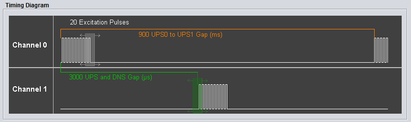
Fig. 8 Interactive Timing Diagram
The interactive timing diagram provides a way to visualize the number of excitation pulses, UPS0 to UPS1 gap, and UPS and DNS gap. Additionally, users can configure the number of pulses and UPS and DNS gap by clicking and dragging the white (pulses) and green (UPS and DNS gap) boxes to the left or right to increase or decrease the current value.
Currently, the USS library implementation does not reflect the timing diagram perfectly. The current library implementation has the UPS0 to UPS1 gap implemented as the end of the last excitation pulse in Channel 1 to the beginning of the next excitation pulse series in Channel 0. Future implementations of the USS library will match the displayed timing diagram, where the UPS0 to UPS1 gap is from the beginning of an excitation series to the beginning of the next excitation series in the same channel.
More Information
- For more information on the application, and available evaluation kits, see the download page.
- For technical support, email the USS GUI support team or visit the MSP430 E2E forum