Technology
Welcome to the technology chapter. This chapter is a detailed overview of the CapTIvate™ peripheral. It covers the principles of measurement and the measurement signal chain that makes everything possible. In addition, the low power features are discussed in conjunction with the wake-on-proximity state machine.
This section describes the CapTIvate™ peripheral and the intended use. This section is broken into analog and digital sections. The analog section describes the measurement technology while the digital section describes the features surrounding the technology to support sensing applications. Throughout this section the peripheral inputs and outputs are described in the context of the CapTIvate™ library structures.
Before discussing the peripheral a short introduction to charge-transfer as a capacitance measurement technology is presented.
Charge Transfer Technology
Charge transfer is an effective way to measure a change in capacitance based upon a fixed capacitance. By means of simple analogy, charge and capacitance are represented by a liquid and a container, as shown in Figure 1. The smaller container is the variable capacitance while the larger container is the fixed capacitance.
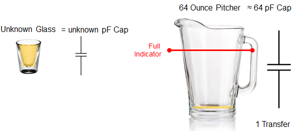
The smaller container is filled (charged) and then emptied (transferred) into the larger container. The number of times it takes to fill the larger container is representative of the volume (capacitance) of the smaller container. If the number of times it takes to fill the larger container changes, then the volume of the smaller container has changed. In most capacitive touch systems, the interest is not in the absolute capacitance but in the change in capacitance. That is when a touch or other interaction occurs, the capacitance of the smaller container changes and consequently the number of times it takes to charge and empty the smaller capacitance into the larger changes. It is this change that is used to determine if a touch occurred.
The CapTIvate™technology allows for two different types of external capacitance to be measured. These two types are called self and mutual capacitance and are described in the next two sections.
Charge and Transfer Phases in Self Mode
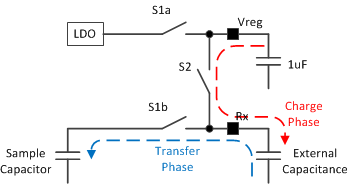
Self capacitance, as explained in the Capacitive Sensing Basics section, is the capacitance relative to earth ground. In order to measure the self capacitance with the CapTIvate™charge transfer implementation, charge is transferred between three difference capacitors, as shown in Figure 2. First, the charge stored on the Vreg capacitor (recommended value of 1uF), is used to charge the external unknown capacitance during the charge phase. Second, the charge from the external capacitance is transferred to an internal sampling capacitor. During this transfer phase when charge is moved from the external capacitor to the sample capacitor the Vreg capacitor is refilled with charge by the LDO. These charge and transfer phases are repeated until the voltage on the internal sampling capacitor changes by the desired amount. As will be discussed in a later chapter, this voltage can be changed to allow for a wide range of external capacitances.
Mutual Mode Charge and Transfer Phases
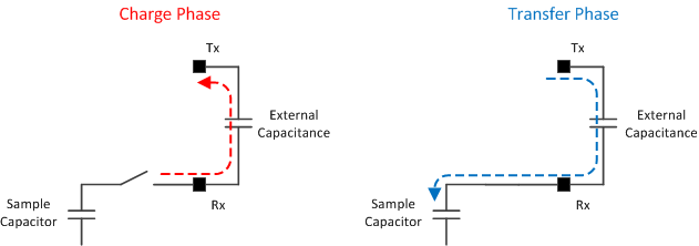
Mutual capacitive mode is the measurement of capacitance between two electrodes; typically a receive (Rx) electrode and a transmit (Tx) electrode. During the charge phase a sample-and-hold circuit drives the Rx node while the Tx node is pulled to ground. In the transfer phase the Tx node is pulled high (driven by Vreg similar to the charge state in self capacitive mode) and the charge across the capacitance is transferred to the sample capacitor.
The CapTIvate™ Peripheral
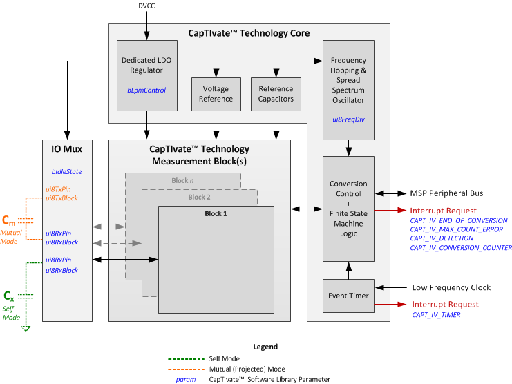
The CapTIvate™peripheral can be described in terms of two main themes or functions: the capacitance measurement and the complimentary digital functions. In Figure 4, the capacitance measurement function is illustrated in the CapTIvate™Measurement blocks and IO mux while the complimentary digital functions are illustrated by the CapTIvate™Core. Depending upon the device configuration, there can be up to 12 measurement blocks and up to 8 measurement inputs per block. The number of blocks will determine the number of measurements that can be made in parallel while the number of pins per block will determine the actual number of IO available for a capacitive touch measurement. So for example, a device with 4 blocks and 4 pins per block can measure 4 elements in parallel and provides 16 CapTIvate™IO. The complimentary digital functions are not directly related to the capacitance touch measurement but enable low power operation, electromagnetic compatibility (EMC) control, and other features.
Capacitance Measurement
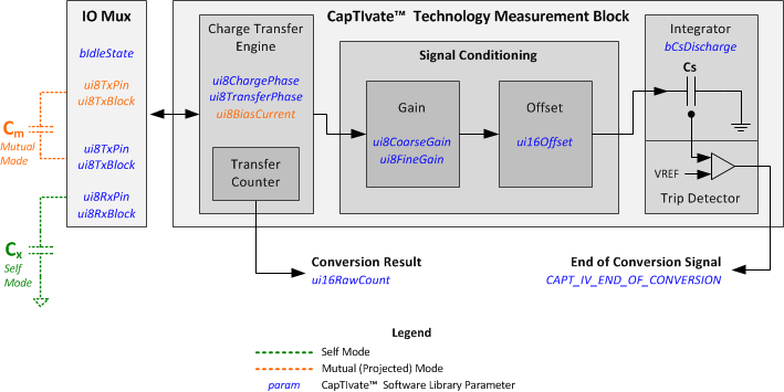
Figure 5 shows the IO Mux control and one instantiation of the CapTIvate™ Measurement Block. The IO mux performs the necessary switching to support mutual and self capacitive mode measurements as well as configuring unused pins as either floating (High-Z) or active low (GND). Within the CapTIvate™ measurement block the technology can be further divided down into sub-blocks to provide a more complete picture and understanding behind the library parameters.
IO Mux
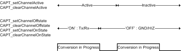
As with most analog peripherals, the IO control can be switched over from the GPIO to the analog functionality by enabling the CapTIvate™function for that IO (refer to the specific datasheet for a description of the IO). In addition to enabling the IO, the CapTIvate™functionality must be defined when the IO is active, when the IO is on (receiver or transmitter), and when the IO is off (ground or high-z). Figure 6 shows the control that is applied to an enabled channel with respect to the conversion.
The CAPT_initUI() API found in CAPT_Manager.h applies the appropriate settings to the IO based upon the sensor settings tSensor.bIdleState and the element definitions tElement.ui8RxBlock, tElement.ui8RxPin, tElement.ui8TxBlock, and tElement.ui8TxPin. It is recommended to use these settings provided through the design center, although additional APIs (like the ones in Figure 6) are provided for custom applications and more unique IO control.
The CapTIvate™Design Center provides the ability to easily configure and develop simple self capacitive mode and mutual capacitive mode structures: self capacitive mode consists of one Rx channel while mutual capacitive mode consists of one Rx and one Tx channel. The modularity of the APIs allows for multiple Tx in the case of mutual capacitive mode or multiple Rx in self capacitive mode. This provides a unique way to unify multiple structures into a single new element. Typically this new element is used as a wake-up mechanism, before transitioning to more traditional separate measurements.
The APIs shown in Figure 6 as well as the CAPT_forceSensorIO API enable a more custom implementation of the IO. Use of these functions, should be done with caution and always in the context of a sensor definition. These APIs do not explicitly configure the mode, ie self of mutual capacitive mode, and therefore it is always important to utilize these parameters within the context of having applied the sensor parameters (CAPT_applySensorParams).
Charge Transfer Engine
As previously discussed, the CapTIvate™technology uses charge transfer to measure relative changes in capacitance. Maintain consistency in measurements is important so that the only change being introduced in the system is the change in capacitance due to a touch or proximity effect. One potential cause for an inconsistent measurement is an incomplete charge and/or transfer phase. This is directly related to the size of the capacitive load being driven. The larger the capacitance, the longer it takes to fully charge and discharge that capacitance. If the charge or transfer phase is too short for the given capacitive load there is a potential for any deviation in the timing to result in a change in the amount of charge being placed on or transferred from the capacitance being measured. Given the exponential nature of the charge and discharge waveforms it is important to control the charge and transfer phase lengths. The control of the charge and transfer phases, and ultimately the conversion rate, is provided in the configuration structure and also can be controlled via the CapTIvate™Design Center.
As shown in the Capacitive Sensing Basics section, in self capacitive mode the parasitic capacitance is in parallel with the electrode capacitance being measured and therefore the charge and phase lengths are adjusted to ensure complete charge and transfer of charge to all capacitances. In mutual capacitive mode; however, there is a distinction between the parasitics to ground and the parasitics associated with the Rx and Tx lines which are in parallel with the mutual capacitance between the Rx and Tx electrodes actually being measured. The phase lengths are adjusted to compensate for the mutual capacitance between the Rx and Tx electrodes and any mutual parasitic capacitance between Rx and Tx lines (this can occur when Rx and Tx are in close proximity to each other when routed on the PCB). This control does not compensate for the parasitic capacitances to ground (primarily on the Rx line) which can have a negative impact on the measurement. In order to compensate for this capacitance an additional control mechanism is in place to strengthen the sample-and-hold amplifier when the parasitic capacitance to ground is large. Similar to the phase control, this compensation is also found in the CapTIvate™ Design Center and the sensor configuration of the CapTIvate™Touch Library. Table 1 shows the applicable charge transfer control mechanisms and the associated CapTIvate™Design Center tuning parameter and CapTIvate™Touch library structure parameter name. These parameters are applied to the peripheral via the HAL API CAPT_applySensorParams.
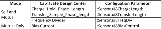
Also shown in Table 1 is the frequency divider. The charge and transfer phase lengths are a function of the divided CapTIvate™oscillator. Therefore it is possible to increase the phase lengths with both the frequency divider and the individual control of the charge and transfer phase lengths.
Signal Conditioning (Sensitivity Related Functions)
Once reliable charge transfers have been established the main issue can be addressed: discerning (small) changes in capacitance. This issue becomes much more challenging as the relative change in capacitance is small when compared to the capacitance being measured. In order to provide sensitivity over a large range of capacitances the CapTIvate™peripheral provides gain and offset functions. These functions are described as the tElement.ui8CoarseGain, tElement.ui8FineGain, and tElement.ui16Offset which are all unique to each element definition in the CapTIvate™ library. These components are automatically tuned for each element in order to achieve the conversion gain and conversion count defined within the sensor.
The conversion count, firstly, describes the conversion time. This number is the number of charge transfers that occur for a non-touch measurement. For example if the charge and transfers phases are each 250ns, then a conversion count of 200 counts would result in a conversion time of ~100us. Secondly, the conversion time is directly proportional to the sensitivity of the system. As the conversion count is increased the relative change in the conversion result, due to touch (increase in capacitance), will increase.
The conversion gain is always less than or equal to the conversion count. The difference between the gain and the count is proportional to the sensitivity of the system and is directly related to the offset compensation. When the conversion gain is equal to the conversion count, no offset compensation is applied and the sensitivity is solely related to the gain. As the conversion gain decreases the amount of offset compensation is increased. By increasing the offset compensation, although the absolute change in capacitance is the same, the relative change in capacitance increases.
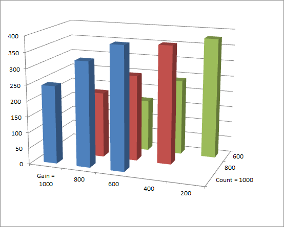
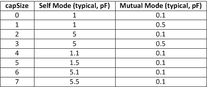
The figure below shows the response of the system to an increase in capacitance (~0.1pF) and how this response can be amplified by changing the conversion gain and conversion count settings. The internal reference capacitor is used to generate the change in capacitance: moving from setting 3 (5.0pF typical) to setting 5 (5.1pF typical).
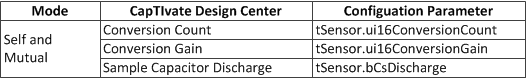
The above table shows the Conversion Count and Gain parameters already discussed and a third parameter, bCsDischarge, which can be used to extend the sensitivity over a greater range of capacitance by setting the value to 0 or 0V. The default setting is 1, or 0.5V, and recommended for most applications.
Auxiliary Digital Functions
In addition to the CapTIvate™capacitive measurement technology, the CapTIvate™ peripheral is composed of several other helper functions to automate and improve the performance as well as provide additional features specifically related to electro-magnetic compatibility (EMC).
Low Power Operation
The CapTIvate™peripheral is designed to make single or multiple measurements without any CPU interaction or other peripheral interaction (typically a timer). This is made possible with an integrated timer and finite state machine.
CapTIvate™Timer
The integrated timer is a standard MSP430 Timer_A implementation without the capture feature.
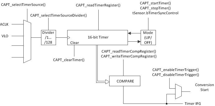
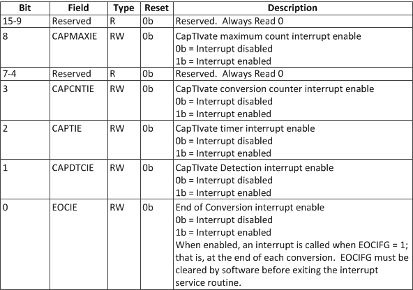
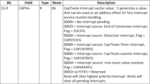
The primary purpose for the timer is to periodically trigger conversion events. The interrupt vector is available and therefore the timer is available to the system as a general purpose timer. Table 3, Table 4, and Table 5 show the interrupt related CapTIvate™registers and specifically the timer associated bits.
Finite State Machine (FSM)
The finite state machine provides several functions to lessen the burden upon the CPU. As mentioned, in conjunction with the timer, the FSM can automate the measurement process so that no CPU interaction is needed until a specified (interrupt) event occurs. This section is divided into four levels of utilization of the FSM: FSM OFF, FSM MANUAL, and FSM AUTO.
FSM OFF
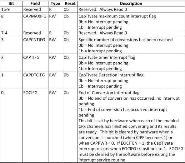
The maximum count error detection is the only FSM logic that remains enabled when the FSM is bypassed (Library API: CAPT_bypassFSM()). The maximum count detection logic, defined as tSensor.ui16ErrorThreshold in the CapTIvate™Library, places a digital limit on the conversion result and consequently a limit on the maximum conversion time. This is particularly helpful to help prevent shorts from negatively impacting the entire system, and provides a mechanism to quickly identify faulty keys. In the event that the maximum count error is exceeded the conversion result is set to 0 and the CAPMAXIFG flag is set, see Table 4.
FSM MANUAL
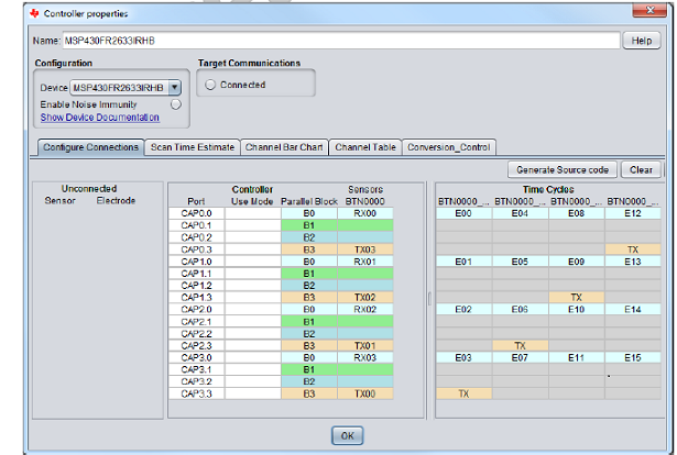
The FSM MANUAL mode enables the FSM but uses the CPU to move the configuration information from the CapTIvate™library configuration to the peripheral and then the results from the peripheral to the CapTIvate™library configuration. This mode is typically used in a multi-cycle sensor implementation. The figure below, shows a classic example of a 16-key keypad divided into 4 4-element cycles. The CPU loads the information for each cycle, performs the measurement, saves the results of the measurement, and then proceeds to the next cycle. During the measurement phase the CPU can enter a low power mode or perform other activities.
In addition to the maximum count error detection logic, detection logic is also added. This detection logic is predicated upon the current filter count value and the upper and lower thresholds.
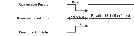
The FSM provides a simple low pass filter, as shown in the figure below, to weight the new filtered count result as a function of the previous filter count and the current conversion result. The weighting is controlled by the input tSensor.ui8CntBeta.
The updated filter count is then compared to the upper and lower bounds. If the filtered count value is within the bounds then no detection occurs. Once the filter count value exceeds the bounds the detection IFG is set (CAPIFG:CAPDTCTIFG, see Table 4).
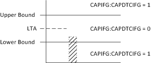
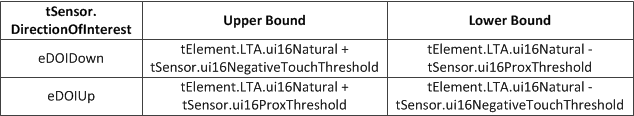
The upper and lower bounds are always relative to the long term average (LTA) and the defined in the negative touch and proximity thresholds. It is important to briefly note that the direction of interest is used to interpret the upper and lower bounds. Direction of interest indicates which direction of change (up or down) will be flagged as a proximity event verses a negative touch.
Once the detection logic has completed, the FSM takes on the task of updating the long term average (LTA). This value has other names; baseline tracking, environmental compensation, etc, but the important concept is that the LTA represents the undisturbed (untouched) system capacitance. Similar to the filter count the LTA is the weighted average of the previous (old) LTA with the new filter count value. The inputs to the LTA calculation are the weighting, tSensor.ui8LTABeta, and the old LTA, tElement.LTA.ui16Natural. Note: The filter count and the LTA are floating point values and the FSM takes care of the floating point math. Only the natural portion is described here since this is what is used for the detection logic.
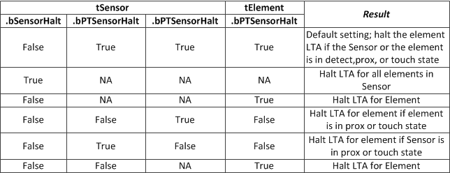
In addition to the filter, the FSM provides mechanisms to halt or suspend the LTA update. This can be an important feature to prevent other touch events from falsely influencing the LTA for a neighboring or surrounding element.
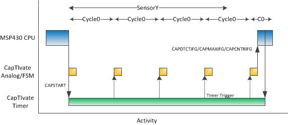
FSM Auto mode
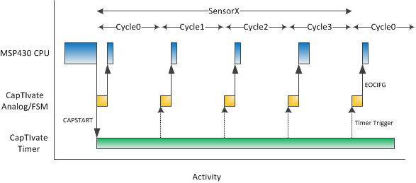
The automatic mode of the FSM is simply the timer triggered conversion, using the CapTIvate™timer described in the earlier section. Similar to the manual mode, the CPU may be used to move data between the CapTIvate™library structures and the CapTIvate™peripheral. Configuring a sensor for timer triggered conversions can be done by setting the tSensor.bTimerSyncControl bit or using the CAPT_enableTimerTrigMeasurement API. Typically the CAPIFG:EOCIFG or associated interrupt, is used in the manual mode to indicate that the measurement is finished and it is time for the CPU to move data to and from the configuration structures and process the cycle results while waiting for or even during the next cycle measurement. This flow is illustrated in the two figures:
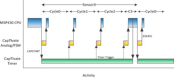
The second figure above is different, illustrating an event of some kind (error, detection, or diagnostic) that requires the CPU to; stop the timer triggered sequence of events, perform some additional processing, and restarting the timer sequence.
Wake on Touch Operation (WOT)
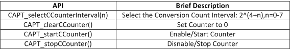
The wake on touch operation (WOT) is a special case of the FSM auto mode where the sensor only has one cycle and no CPU operation is required to load new cycle related values. Specifically the LTA and filter count values are updated by the FSM and are available within the peripheral for successive measurements. As shown in the figure below, cycle 0 is repeatedly measured without CPU interaction. Additionally, in the figure in the previous section, the EOCIFG is used to trigger post processing of the cycle and/or sensor at which time different event flags are read and acted upon. During WOT these events are reconfigured to generate an interrupt and request CPU interaction. The specific interrupts used are the detection interrupt (CAPDTCIEN), the maximum counter error interrupt (CAPMAXIEN), and the conversion counter interrupt (CAPCNTRIEN), see the table.
The detection and maximum count events have been described in previous chapters. The conversion counter interrupt is a unique counter which counts the number of conversions and generates an interrupt when a certain number (of conversions) is reached. This provides a defined wake-up period specifically for diagnostic purposes to ensure that the LTA and filter count values are within an expected range or perform self-tests.
Conversion Timing
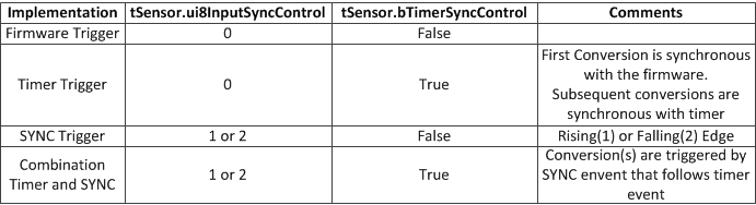
The start of a capacitance to digital conversion can be triggered from software, the CapTIvate™timer, the external SYNC pin, or a combination.
A conversion can be initiated from a number of APIs. However, when the actual conversion takes place is a function of the sensor settings. For example, when the ui8InputSyncControl field in the sensor structure is set, the conversion will not take place until the appropriate edge is seen on the SYNC input pin.
EMC
The CapTIvate™peripheral provides several features to support EMC in terms of emissions and susceptibility.
Emissions
The spread-spectrum feature of the charge-transfer frequency sweeps the frequency linearly about the center frequency. This spreads the amount of energy radiated in the frequency and thus reduces the peak power radiated at the center frequency. This feature is enabled by simply setting the Boolean tSensor.bModEnable in the sensor configuration.
It is recommended, when modulation is enabled, to make the conversion count a multiple of 40. This helps to ensure that the number of samples (charge-transfer cycles) below the center frequency are equivalent to the number of samples taken above the center frequency
Susceptibility
Susceptibility can be reduced by measures in both the time a frequency domains. In the time domain, a SYNC input is provided to trigger the conversion event. This is helpful in extremely noisy AC systems when the best time to do the conversion is during the zero-crossing of the AC waveform. In the frequency domain, a frequency hopping feature is provided to move the charge-transfer frequency out of the band where noise is present. The CapTIvate™peripheral includes a dedicated oscillator which can configured to provide 16Mhz, 14.7Mhz, 13.1Mhz, or 11.2Mhz. These frequencies can be further divided down by the tSensor.ui8FreqDiv parameter as discussed in an earlier section. Automatic control over the oscillator is provided within the noise immunity features of the CapTIvate™library.
Reference Capacitors
The CapTIvate™peripheral also comes equipped with a set of reference or self-test capacitors. These capacitors vary in size and can be measured in parallel with an eternal load or independent of the external connection as a self-test mechanism. There is only one reference test bank of capacitors, so only one block can be tested at a time. Applying the reference capacitor is done with the MAP_CAPT_enableRefCap() API. Similar to the channel IO control APIs this API must be called within the context of a sensor and the sensor parameters must have been applied (MAP_CAPT_apply_SensorParams). The reference capacitor size is dependent upon the mode (mutual or self) as defined by the sensor.
Removing the reference capacitor from the measurement circuit is done by simply calling the API, MAP_CAPTdisableRefCap().