DRV8889-Q1 Hardware User Guide
1. Hardware Required
LP-MSPM0L1306 - MSPM0L1306 Launchpad
DRV8889-Q1EVM - DRV8889-Q1 automotive stepper driver with 1/256 microstepping and stall detection evaluation module
DC Power supply that supports the required voltage and current
Stepper Motor
13 jumper wires (to connect LP to EVM)
Micro-USB cable
2. Hardware Setup
Connect jumper J9 and J10 in the LP-MSPM0L1306 as shown below.

Fig. 13 J9 and J10 header connected to 3V side in LP-MSPM0L1306
Connect a jumper between pin 9 and 11 in the J2 header of the DRV8889-Q1EVM board.

Fig. 14 J2 header in DRV8889-Q1EVM
Connect the LP-MSPM0L1306 to the DRV8889-Q1EVM using the jumper wires as shown in the table below. Refer to the schematic connector pinout for the locations of the DRV8889-Q1EVM signals.
Connection |
MSPM0L LP |
DRV8889-Q1EVM |
Jumper Notes |
|---|---|---|---|
Fault Input |
PA5 |
nFAULT |
|
Current reference output |
PA22 |
VREF |
|
Chip Select |
PA15 |
nSCS |
|
Logic level for SDO |
3V3 |
VSDO |
|
Serial data output |
PA16 |
SDO |
|
Serial data input |
PA18 |
SDI |
|
Serial clock input |
PA6 |
SCLK |
|
Step input |
PA12 |
STEP |
|
Direction input |
PA0 |
DIR |
J10 connect to 3V side |
Disable output |
PA3 |
DRVOFF |
|
Sleep mode input |
PA1 |
nSLEEP |
J9 connect to 3V side |
Common Ground |
GND |
GND |
Connect the A phases of the motor to AOUT1, AOUT2 and the B phases to BOUT1 and BOUT2 of the motor connector terminal block on the DRV8889-Q1EVM. If the phases of the motor are color coded, look into the motor datasheet to find the phases.
Set the power supply voltage to desired voltage (less than 45V) and turn the power supply outputs off. Connect the positive and negative of the power supply to VM and PGND/GND of the power connector terminal block to the DRV8889-Q1EVM. Do not turn the power on yet. See the connection below.
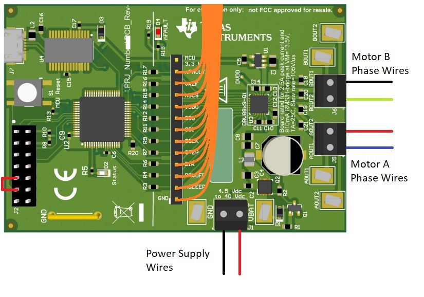
Fig. 15 Motor wires and Power supply connection in DRV8889-Q1EVM
Note : The motor phase wire colours shown above are for representation it will not be same for every motor, so please refer to motor datasheet to verify the motor phase wires for your motor.
Connect a Micro-USB cable from the LP-MSPM0L1306 to the PC.
Set the power supply to the motor voltage and with current limit of motor current limit( if motor rated current is higher than 1.5A please keep to 1.5A ). Turn on the power supply.
Once all steps are completed you can start to run the motor with the GUI. Please refer to GUI User Guide.