DRV8411A GUI User Guide
The GUI used in this guide can be found here.
1. Getting Started with GUI
The GUI allows the user to configure various settings required for stepper motor control. The user can adjust settings like motor speed, control direction, control step movements and other device settings, as well as monitor the device status.
Perform the following steps to begin using the GUI:
Connect the stepper motor to the EVM.
Make the necessary connections for connecting LP-MSPM0L1306 to DRV8411AEVM. For detailed steps refer to Hardware User Guide.
Plug in the micro-USB cable to the PC.
Enable the power supply to EVM.
2. Using the GUI
The GUI when launched will automatically try to establish communication with the device, if it doesn’t happen or if user needs to disconnect the user can click on the link icon shown on the left side in the image shown below. A message showing ‘Connecting to target…’ will be displayed when the GUI tries to connect to the board in the hardware connection status pane which is located at the bottom of GUI window. If the connection is successful, ‘Hardware connected’ message appears, as shown in the image below.

Fig. 2 Hardware connected
3. GUI Window
In the GUI Window user can find various controls to sleep/wake the driver, control the stepper motor, and configure various parameters such as step mode, control mode, and so forth. Hover over the control widgets to display the brief description on its actions.
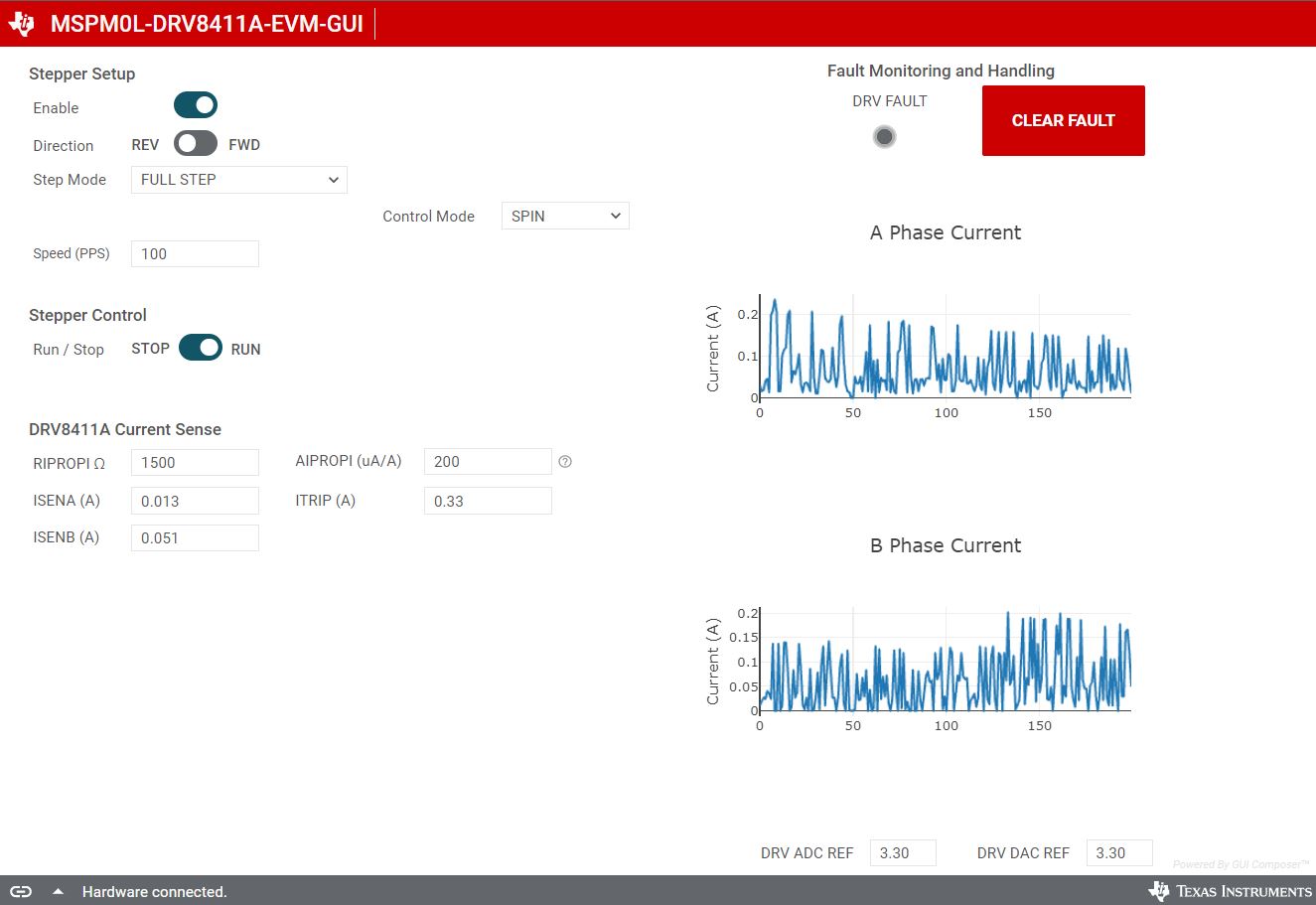
Fig. 3 GUI window
4. Control Modes
Spin Mode
Spin mode allows to spin the stepper motor in the desired speed. The desired speed is set in units of pulse per second. Knowing the motor Pulse per rotation and the step mode we can compute the RPS(Revolutions Per Second) of the motor. For example, for a motor of 200PPR speed of 200PPS equates to 1RPS in Full step mode and 0.5RPS in Half Step mode.
Stepper controls are enabled only when the ‘Motor Driver’ is enabled. When the Stepper control is set to ‘RUN’ the motor starts spinning at the speed set in the speed input box. Do note to set the speed in the limit of the motor specifications, else the motor will not spin i.e. would appear to vibrate as the necessary torque to spin is not received in the set speed.
Step Mode
Step mode allows user to move the stepper motor a configured number of steps. Stepper controls are enabled only when the ‘Motor Driver’ is enabled. When the Stepper control is set to ‘RUN’ the motor starts spinning at the speed set in the speed input box and when the number of steps entered in the steps input box is reached, the motor stops.
5. Decay Modes
Decay mode controls the current recirculation in the H-bridge when the drive is in decay state. This setting only is used in Half step Non-circular mode, there are 2 values to select “SLOW “, and “FAST”, the user is required to selecting the decay based on the noise reduction. Generally SLOW decay is preferred.
6. Fault Monitoring and Handling
The fault monitoring and handling is at the top right side of the screen this allows the user to monitor the faults. The Fault led turns red when a fault occurred. To clear the fault, use the “CLEAR FAULT” button.
7. Current Sensing
RIPROPI and AIPROPI
The DRV8411A sends a current reduced by a factor AIPROPI through the RIPROPI resistor. The user is required to set the RIPROPI value as set in the hardware to get the proper current reading.
ISENSE
The GUI displays the instantaneous currents flowing through the A phase and B phase windings in ISENA and ISENB value respectively.
ITRIP
The GUI allows user to set the trip current for the stepper motor, the driver sends this current through each of the motor phase windings.
Phase Current Plots
The user can see a graphical view of the motor phase currents using the plots in the GUI. The GUI can capture the phase currents and show it to the user as a graphical representation.

Fig. 4 GUI plot