|
AM64x MCU+ SDK
12.00.00
|
|
|
AM64x MCU+ SDK
12.00.00
|
|
This section is aimed at explaining what a bootloader is, why is it needed and details regarding the bootloader and bootflow used in the MCU+SDK.
Generally speaking, bootloader is a piece of software / firmware that runs as soon as you power on an SoC. A bootloader's main duty is to start the subsequent pieces of software, such an OS, a baremetal application or in some cases another bootloader. When it comes to embedded, the bootloader is usually closely tied with the underlying SoC architecture. The bootloader is usually stored in a protected, non-volatile on-chip memory. Typically the bootloader performs various hardware checks, initializes the processor and configures the SoC registers etc. Since the primary aim of the bootloader is to load the next piece of software, it needs to communicate to the external world to receive this firmware/application image. This can be over a number of protocols - USB, UART, SPI, I2C, External Flash, Internal Flash, SD Card, Ethernet, CAN etc. Bootloader is also a key component in embedded security. Hardware Root-of-Trust is usually passed onto the bootloader and is passed on down the line.
As mentioned earlier, sometimes the bootloader would be loading another bootloader which can load another one and so on. This is usually the case in advanced SoCs, and there are various reasons for this. The first bootloader is usually kept on secure, read-only memory for security reasons and to have a known state always before application software starts. It makes sense then to keep this bootloader simple and let it do only the bare minimum configuration required. This secondary bootloader can be complex and configurable to suit the needs of the application. This can also be updated easily compared to the first stage bootloader. In fact for the devices in MCU+SDK, we have a two-stage bootloading - the first stage bootloader is called ROM Bootloader (RBL) and the second stage bootloader is called Secondary Bootloader (SBL).
Multi-core bootloading is almost always a follow up when there is a multi-stage bootloading. In this case the first bootloader technically might not be even aware of the other cores, it will just boot the next stage bootloader and this second stage bootloader will take care of the complex bootloading on the different cores.
Loading a multi-core application is slightly more complicated than loading a single core application. There would be concerns regarding image preparation, shared memory access, and so on. Mostly there would be a particular format in which the individual core images are created, and then they may/may not be concatenated into a single image for SBL to load. Whatever format the application image is in, the SBL should be aware of it so that it can parse and load the image correctly.
In the MCU+SDK, the bootflow takes place mainly in two steps after you power ON the device
The RBL or ROM Bootloader is stored in read-only memory and is almost considered as part of the SoC. The details regarding the RBL and ROM Boot is out of scope for this user guide. Please refer to the Technical Reference Manual of the device for more details. But basically the ROM expects an x509 signed binary image of the secondary bootloader to be provided for boot.
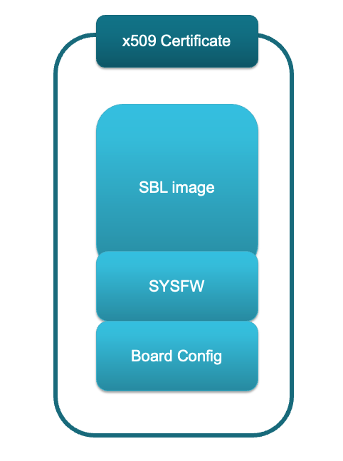
The x509 template for ROM looks something like this:
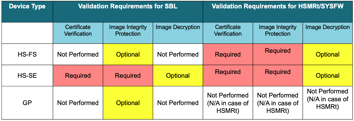
Depending on the device type, these are the validation requirements for ROM:
source/drivers/sciclient/soc/${soc}:sysfw-hs-fs-enc.bin: This is the encrypted and signed SYSFW binary to be packaged with SBL when preparing the SBL boot image for HS-FS device.sysfw-hs-fs-enc-cert.bin: This is the x509 certificate binary generated while signing the above (sysfw-hs-fs-enc.bin) image. This is also to be packaged with SBL when preparing the SBL boot image for HS-FS device.sysfw-hs-enc.bin: This is the encrypted and signed SYSFW binary to be packaged with SBL when preparing the SBL boot image for HS-SE device.sysfw-hs-enc-cert.bin: This is the x509 certificate binary generated while signing the above (sysfw-hs-enc.bin) image. This is also to be packaged with SBL when preparing the SBL boot image for HS-SE device.The SBL is like any other application, created using the same compiler and linker toolchain. It is an example implementation rather than a deliverable. It is customizable by users, but must adhere to the requirements by RBL which is a constant as mentioned above. However the steps to convert the application .out into a bootable image are different for SBL as listed below:
main(), make sure to call Bootloader_socWaitForFWBoot to wait for the boot notification from the SYSFW0x70000000 and this is the entry point for the SBL.0x70000000 to 0x70080000 should be used by SBL code, data, stack etc.out file is first converted to a binary format .bin using the TI ARM CLANG objcopy tool.objcopy fills the gaps with 0x00..bin file is then signed using the Signing Scripts to create the final .tiimage bootable image..tiimage file extension is kept to separate the SBL boot image from a normal application image.bin file.tiimage extension like so:sbl_xxx.release.tiimage [No prefix before .tiimage, plain image]sbl_xxx.release.hs_fs.tiimage [hs_fs prefix before .tiimage]sbl_xxx.release.hs.tiimage [hs prefix before .tiimage]hs it is meant for HS-SE device and hs_fs or hs-fs is meant for HS-FS device..tiimage file can then be flashed or copied to a boot image using the Flashing Tools

Now, as mentioned above, to boot an application with SBL it has to be specially prepared after it's compiled.
makefile_ccs_bootimage_gen that is included in every example and secondary bootloader (SBL) CCS project.makefile in the example folder.Shown below are the different steps that are done to convert the compiler+linker generated application .out into a format suitable for flashing and booting
genimage_am64x.py takes each individual core's .out file as input and combines them to form a .mcelf file..mcelf file is then flashed to the board.

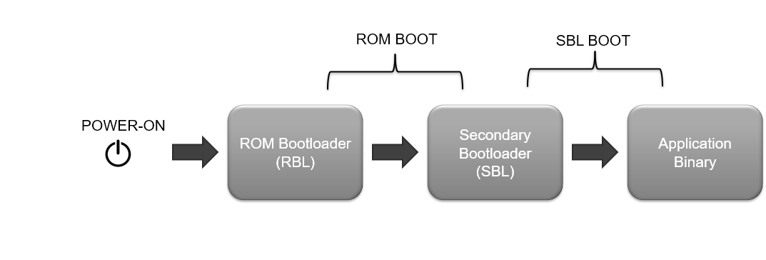
After a SBL and application image is flashed, shown below is the high level boot flow, after the SOC is powered on.
In secure device variants, there are slight differences in the bootflow. For details on secure boot, please refer Enabling Secure Boot
The SBL is like any other example of the SDK. They use the bootloader library APIs to carry out the bootloading process. Depending on the boot media from which we load the application binary, we have multiple SBLs like sbl_ospi,sbl_uart etc. A bare minimum SBL called the sbl_null is also included which aids the users to load their applications via CCS. Here are some details regarding those.
sbl_null is a secondary bootloader which doesn't load any application binary, but just does the SOC initialization and puts all the cores in WFI (Wait For Interrupt) mode.sbl_null is an alternative to this process.sbl_null is the only option to initialize the device in this case.sbl_sd is a secondary bootloader which reads the application image file from the SD card and then moves on to core initialization and other stepssbl_sd, the application image needs to be copied to the SD card as a file named "app". Make sure that the SD card is formatted to have a FAT partition. To know more about the SD card partitioning please refer SOC Initialization Using SD BOOTsbl_sd binary and the application image binary has to be present as files in the SD card. You have to rename the sbl_sd appimage as 'tiboot3.bin'. copy file to SD card => ${SDK_INSTALL_PATH}/tools/boot/sbl_prebuilt/am64x-evm/sbl_sd.release.hs_fs.tiimage
rename in SD card as => tiboot3.bin
sbl_sd reads the full appimage file into an MSRAM buffer and then parses the multicore appimage. Because of this reason appimages higher than ~380 KB in size can't be booted by sbl_sd as of now.sbl_ospi is a secondary bootloader which reads and parses the application image from a location in the OSPI flash and then moves on to core initialization and other stepssbl_ospi, the application image needs to be flashed at a particular location in the OSPI flash memory.sbl_ospi application. Currently this is 0x80000. This offset is chosen under the assumption that the sbl_ospi application takes at max 512 KB from the start of the flash. If a custom bootloader is used, make sure that this offset is chosen in such a way that it is greater than the size of the bootloader which is being flashed and also aligns with the block size of the flash.sbl_ospi_multipartition is a secondary bootloader which reads and parses core-specific application images for a system project from pre-defined locations in the OSPI flash and then moves on to core initialization and other stepssbl_ospi_multipartition, the application images needs to be flashed at specific locations in the OSPI flash memory. The default offsets are 512 KB apart.sbl_ospi_multipartition application.sbl_ospi_multipartition here: SBL OSPI Multi-Partitionsbl_uart is a secondary bootloader which receives the multicore appimage via UART, stores it in memory and then does the parsing, core initialization etc.sbl_uart, you can refer to UART Bootloader Python Script subsection. Detailed steps on the usage is mentioned in the same subsection.sbl pcie is a secondary bootloader which receives the multicore appimage via PCIe to memory and then does the parsing, core initialization etc.sbl pcie is send over to the target board from a host board running SBL PCIE HOST.sbl pcie, you can refer to SBL PCIE.sbl_emmc is a secondary bootloader which reads and parses the application image from a location in the eMMC and then moves on to core initialization and other steps.sbl_emmc, the application image needs to be flashed at a particular location in the eMMC.sbl_emmc application. Currently this is 0x800000.sbl_ospi_linux is a secondary bootloader which boots Linux on A53 core and RTOS/NORTOS application on R5, M4 cores.sbl_ospi_linux, the Linux appimage (see Linux Appimage Generator Tool) and the RTOS/NORTOS application images needs to be flashed at a particular location in the OSPI flash memory.sbl_ospi_linux application. Currently this is 0x80000 for RTOS/NORTOS images and 0x300000 for Linux application image.sbl_emmc_linux is a secondary bootloader which boots Linux on A53 core and RTOS/NORTOS application on R5, M4 cores from eMMC.sbl_emmc_linux, the Linux appimage (see Linux Appimage Generator Tool) and the RTOS/NORTOS application images needs to be flashed at a particular location in the eMMC.sbl_emmc_linux application. Currently this is 0x800000 for RTOS/NORTOS images and 0xA00000 for Linux application image. In most cases you wouldn't need to change this.See also these additional pages for more details and examples about the boot flow,
 1.8.20