|
AM64x MCU+ SDK
08.02.00
|


|
|
AM64x MCU+ SDK
08.02.00
|
|
This example uses ADC ICs from the below list to convert analog input signal on adc channels to samples and store the results in a shared memory which can be configured by the user (using PRU IPC module). The read samples are finally printed to the R5F console, or can also be visualized using CCS Graph plotter. GUI Composer app available on TI Gallery can also be used to evaluate the ADC using a GUI based interface.
The example does the below
| Parameter | Value |
|---|---|
| CPU + OS | r5fss0-0 freertos |
| ICSSG | ICSSG0 - PRU0 |
| Toolchain | ti-arm-clang, pru-cgt |
| Board | am64x-evm |
| Example folder | examples/pru_io/adc/ads85x8/ |
Build only the R5F project using the CCS project menu (see Using SDK with CCS Projects).
C:/ti/Supported:
Not Supported:
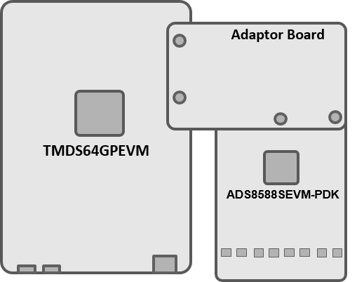
To evaluate ADS8598H use the ADS8588SEVM-PDK but solder the ADS8598H part in place of ADS8588S. To connect the boards use T&M SEM Adapter Board, and connect it with ADC EVM and AM64x GP EVM
| Folder/Files | Description |
|---|---|
| ${SDK_INSTALL_PATH}/source/pru_io/ | |
| firmware/ | PRU source files providing macros for interfaces, pru_ipc, etc. |
| driver/ | PRU IPC source files for sending ADC samples from PRU to R5F |
Shown below is a sample output when the application is run:
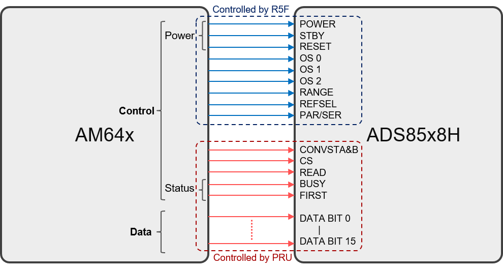
The control of ADC pins is divided between PRU and R5F cores as shown:
m_sign_ext_32bit in examples/pru_io/adc/ads85x8/firmware/main.asm with m_sign_ext_16to32_bits.Refer to PRU Source Macros Documentation for making changes to PRU firmware.
 1.8.20