|
AM64x MCU+ SDK
08.00.00
|


|
|
AM64x MCU+ SDK
08.00.00
|
|
This software is designed for the TI SoCs with PRU-ICSS IP to enable customers add Profinet Device protocol support to their system. It provides Profinet ASIC like functionality integrated into TI SoCs.
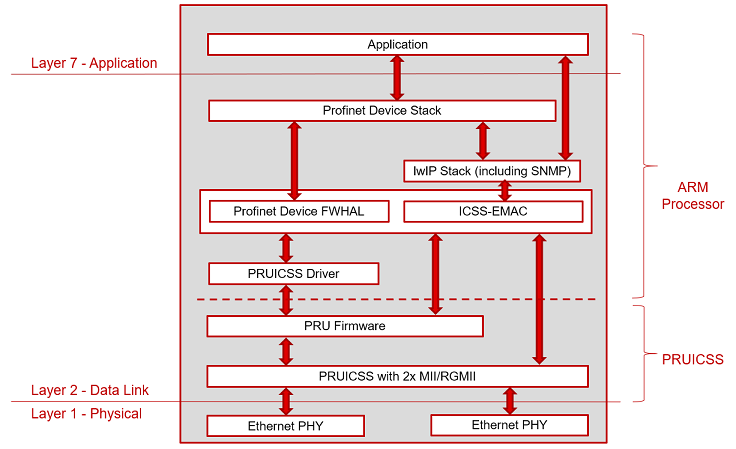
Profinet firmware for PRU-ICSS is a black box product maintained by TI. Profinet Device FWHAL (Firmware and Hardware Abstraction Layer) allows loading and run Profinet firmware and acts as an interface with the firmware.
| Record ID | Details | Workaround |
|---|---|---|
| PINDSW-4725 | PLC communication unstable with Profinet IRT Device in RGMII mode | - |
| PINDSW-4727 | Different Access Ways Test failing with Profinet IRT application | - |
| PINDSW-4922 | SPIRTA Test failures with Profinet IRT application on AM64x | - |
| Folder/Files | Description |
|---|---|
| ${SDK_INSTALL_PATH}/examples/industrial_protocols | |
| profinet_device_rt_demo | Profinet Device RT Example |
| ${SDK_INSTALL_PATH}/source/industrial_protocols/profinet_device | |
| icss_fwhal/firmware | Firmware for the PRU cores in PRU-ICSS. Firmware Version : 0.14.5 |
| icss_fwhal/lib/ | FWHAL library for Profinet Device |
| icss_fwhal/*.c | FWHAL source files |
| icss_fwhal/*.h | FWHAL interface files |
| stack | Stack header files and stack library |
| Abbreviation | Expansion |
|---|---|
| PRU-ICSS | Programmable Real-Time Unit Industrial Communication Subsystem |
| CPM | Consumer Protocol Machine |
| PPM | Producer Protocol Machine |
| DHT | Data Hold Timer |
| AR | Application Relation |
| NRT | Non Real Time |
| LLDP | Link Layer Discovery Protocol |
| MRP | Media Redundancy Protocol |
| DCP | Discovery and Basic Configuration Protocol |
Profinet Device FWHAL implements the key interface between Profinet Device firmware and Profinet Device firm stack. It provides stack interface for CPM/PPM management, Triple Buffer Management, MRP, DCP Filter, Multicast Filter, Phase management and PTCP modules.
Please see APIs for Profinet Device FWHAL for API documentation.
Profinet examples use the ICSS-EMAC as its base switch layer. The PRU Firmware is customized for Profinet functionalities. The NRT (non-real time) traffic is handled by ICSS-EMAC, wherein the packets are forwarded either to the TCP stack or a custom custom callback (configurable in ICSS-EMAC).
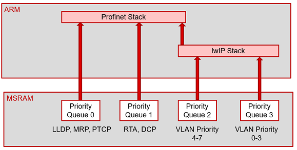
In case of Profinet firmware, the queues are designed as shown in the diagram below. The highest priority queues are used for LLDP, MRP, DCP, RTA and PTCP. These packets are directly forwarded to the registered callback in ICSS-EMAC (using rxRTCallBack). And the Queues 2 and 3 are forwarded to TCP/IP. Profinet FWHAL and stack also uses the TX/RX APIs available in the ICSS-EMAC for transmission/reception of packets like PTCP, LLDP, etc. More info on ICSS-EMAC can be found here.
This section describes the OS entities used by Profinet Device FWHAL.
Profinet Device firmware generates the following interrupts.
8 Host Interrupts (Host Interrupts 2 through 9) are exported from the PRU_ICSSG internal INTC for signaling the device level interrupt controllers. PRU_EVTOUT0 to PRU_EVTOUT7 corresponds to these eight interrupts in the following table. Please check PRUICSS Interrupt Controller section for more details.
| Name | Host Interrupt | Description |
|---|---|---|
| Frame Receive | PRU_EVTOUT0 | Notifies host when firmware has stored a frame in host receive queue |
| PPM Frame Transmit Completion | PRU_EVTOUT1 | Raised when firmware has transmitted a PPM frame |
| CPM Frame Receive | PRU_EVTOUT2 | On reception of CPM frame firmware raises this interrupt |
| DHT | PRU_EVTOUT3 | Firmware notifies DHT event and PPM list toggle event to host through this interrupt |
| PTCP | PRU_EVTOUT4 | Firmware notifies reception of RTSync frame |
| Link Change | PRU_EVTOUT6 | Interrupt is raised when the link on Ethernet PHY comes up or goes down |
| ISOM | PRU_EVTOUT7 | Interrupt is raised ISOM event occurs. Applicable for ISOM Interrupt mode only |
| Task Function Name | Description |
|---|---|
| PN_PTCP_task | PTCP delay measurement scheduling |
| PN_PTCP_syncMonitorTask | PTCP sync monitor scheduling |
| PN_IRT_legacyTask | Legacy startup mode scheduling |
| PN_MRP_CPMTask | MRP Task to control flush mode of ICSS |
| PN_tapWatchDog_task | Tap the ICSS WatchDog Timer |
| Name | Description |
|---|---|
| ptcpStartSem | Indicates start of PTCP |
| ptcpTriggerMeasurementSem | Triggers delay measurement |
Profinet FWHAL supports upto 8 PPMs and CPMs. These CPMs/PPMs are managed internally as two lists of type (t_descList). In case of PPM, the descriptor buffer (pDescs of t_descList) has two instances to maintain an ACTIVE_LIST and SHADOW_LIST of buffers. Any data update to the PPM descriptors happens only on the SHADOW_LIST. This data is picked up by the PRU after a list toggle (PN_togglePpmList), which is currently done in the PN_insPpmList. In the PPM descritor list, at any time the descriptors are sorted by port and phase, which is done by an internal API (PN_writeSortedList). CPM does not have the concept of Shadow and Active list. The API definitions can be found here.
The initialization of the Profinet system, lists and buffers are done in PN_initDrv. All the OS related initializations are done in PN_initOs.
Taking a deeper look at PN_initDrv, it initializes the following (in order of execution):
PN_initLists initializes the t_descList and PN_clearList)Once PN_initDrv and PN_initOs is done, the driver memory (descriptor buffers) have to be initialized. This is done by the API PN_cfgRtcMem. This API initializes two things :
PN_initRtcBuffs).Whenever a connection has to be established, the stack should update the connection data in the internal driver lists. This can be done using the APIs PN_insPpmList and PN_insCpmList. For configuring the CPM/PPM lists, the stack has to first allocate a buffer (in the driver). This can be done using PN_allocPkt. This initializes the packet input to the API, finds a free slot in the list (ppmPkts/cpmPkts of currPN of PN_Handle) and allocates a particular block t_ppmBlock or t_cpmBlock to the buffer.
Once the buffer is allocated, the stack can update the data in the structure (t_rtcPacket) and call PN_insPpmList to update the driver with the new data. This API sorts the t_descList in terms of Port and Phase and requests the PRU to toggle the list (i.e., shadow to active list) using PN_togglePpmList . When the PRU is ready, it toggles the list and sends out the new data (also fires the PN_ppmIsrHandler).
Similar to establishing a connection in PPM, PN_insCpmList is used to update the driver with a new connection. As the concept of Shadow lists is not present in CPM, the data is directly inserted to the list using PN_writeCpmDesc. It also locks the PROC buffer (PROC buffer is explained in Triple Buffer Management).
Once the connection is established, the CPM and PPM data can be updated using the Triple Buffer Scheme. Read more about it here.
The Triple Buffer scheme ensures that the stack or PRU always finds a buffer to update. In case of PPM, the stack is the Producer and PRU consumes this, and in case of CPM, the PRU is the producer and Stack consumes this. Each CPM/PPM descriptor has three buffers associated with it, these buffers are indexed by three pointers - next, last and proc (in t_rtcPacket). There is also a validLast flag in the same structure that indicates there is an update in data (CPM or PPM, set correspondingly by PRU or stack).
The API definitions can be found here.
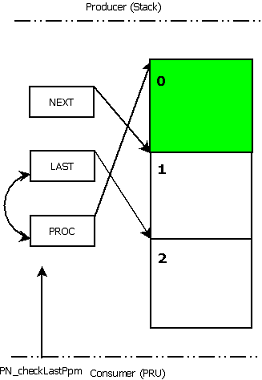
In case of PPM, the stack is the Producer, and PRU consumes it to send it out on the wire.
When the stack has a new PPM to be updated to send, it calls the API PN_getPpmBuff, which returns the a free buffer in the triple buffer(NEXT). The stack then starts updating data in NEXT (marked by grey box in the following diagram).
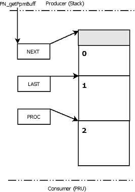
When the stack has completed updating data (marked by Green box in the following diagram to NEXT, it calls the API PN_relPpmBuff. At this point, the LAST index and NEXT index is swapped. This means that the LAST data (previous) is discarded and we have a new LAST data (the validLast flag is set). If the stack wants to further update new data, the NEXT pointer is again used.
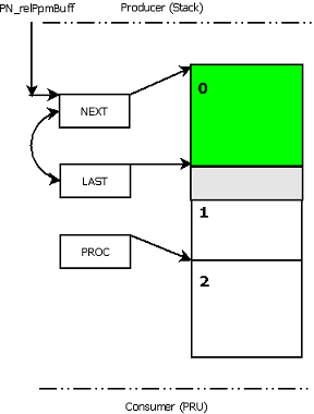
Next, when the PRU is ready to update data (which is send on the wire), PN_checkLastPPM is triggered. At this point, the PROC and LAST indexes are swapped. This enables PRU to send the LAST data, which is the latest available PPM data at any point of time. The validLast flag is cleared, which indicates the PRU that there is no update in the data. Afer this, the stack has NEXT and LAST buffers to update future data (in a ping pong fashion) as shown in Figure 1.
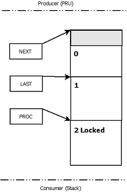
In case of CPM, the PRU is the Producer, and the stack consumes it to use the data.
The stack always reads from the PROC buffer and also has it locked using PN_cpmBuffLock. The PRU never writes into this buffer. Figure 4 shows that the PRU is writing in NEXT buffer, while PROC (Buffer 2) is locked by the stack.
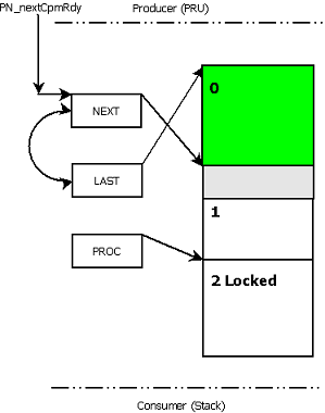
When the PRU has new data to be written, the NEXT and LAST indexes are swapped. This indicates that LAST is pointed to the latest available data (to be consumed by the stack). If the PRU has updated data to be written, it uses the NEXT buffer. The PRU keeps continuing in the loop i.e., switching the NEXT and LAST buffers in a ping pong fashion till the stack consumes the LAST data.
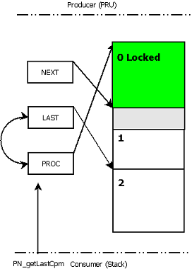
When the stack is ready to consume new data, it calls the API PN_getLastCpm. A swap of LAST and PROC indexes in done here. This indicates the stack consumes the latest data available at any point of time. The stack also should lock the buffer using PN_cpmBuffLock. At this point PRU starts updating any new data in the NEXT buffer.
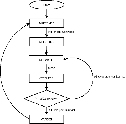
A state machine is implemented by PN_MRP_CPMTask to implement MRP. If a break is detected in the topology, this state machine switches to a state where the PRU sends PPM on both ports. It is also made sure that the FDB for both the ports are cleared. Once all the CPMs learn the correct port number (port of t_rtcPacket), the flush mode is deactivated. The API definitions are present here.
MRP_SUPPORT in ${SDK_INSTALL_PATH}/source/industrial_protocols/profinet_device/RT_MRP/pnDrvConfig.h fileThe MRP state machine has 5 states defined by tMrpStates. The state machine flow chart is shown in Figure 7.
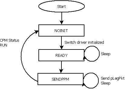
The Profinet IRT Legacy startup feature is implemented using a state machine PN_IRT_legacyTask.
Before a connection is established(i.e., RTC_CPM_STATUS_OFFSET is not set to RTC_CPM_RUN), if legacy mode is enabled, the driver configures a PPM packet to be send in Green period. The API definitions are present here.
IRT_LEGACY_STARTUP_SUPPORT in ${SDK_INSTALL_PATH}/source/industrial_protocols/profinet_device/IRT/pnDrvConfig.h fileThe IRT Legacy Startup state machine has 4 states defined by tLegStates. The state machine flow charts is shown in Figure 8.
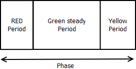
irtLegStateCall. When this is done, the driver will send out the latest PPM data from pLegPkt (which is set by the callback irtLegPktCall). The driver calls the callback in insPpmList if the input param to the API has legMode configured). The packet is send out in intervals, till the connection is established.Every cycle in Profinet IRT is split into a RED and GREEN period. The driver has APIs to configure these periods, which is mostly done during establishment of connection. GREEN period can be further classified into Green steady period and Yellow period. If a packet has to be transmitted during Yellow period, the driver has to check if the packet can be send out in the remaining time left. Otherwise it is send out in the next green period. The API definitions are present here.
The API definitions are present here.
PTCP is implemented in the PRU and PTCP driver. It mainly has two parts
PTCP has an ISR PN_PTCP_isrHandler which is triggered when a SYNC packet is received from the PRU. The ISR internally calls an important API PN_PTCP_syncHandling which calculates the deltaT between the master and slave, and according initiates the clock adjustment process. There is also a filter implemented which makes sure the compensation is done only once the deltaT is stable. The clock adjustment process is handled as a chain of transfers from ECAP->EDMA->IEP. An ecap period is set based on the the calculated adjustment deltaT. At this ECAP period internal, ECAP generates an event which triggers an EDMA transfer from a predifined location(IEP_CONFIG_ADJ_OFFSET) to the IEP registers. This decides if the IEP has to be compensated more (+ve) or less (-ve). This chain mechanism ensures that the value to be compensated is spread out smoothly through the sync cycle time. The driver also maintains a task PN_PTCP_syncMonitorTask to monitor if there is a sync timeout.
Another task PN_PTCP_task does the handling of delays (cable delay, line delay etc.). This task sends out multiple delay requests in a particular interval, and processes the delay responses(PN_PTCP_delayMeasurement). The calculated line delays (deviceDelays_t) and port delays (ptcpPortDelayVal_t) are stored in the internal structures.
The driver provides two main callbacks that can be used by the stack for certain even triggers. They are ptcpSyncStatusCall and ptcpDelayUpdateCall (which can be registered by calling the APIs PN_PTCP_registerSyncStatusCall and PN_PTCP_registerDelayUpdateCall). The ptcpDelayUpdateCall is triggered whenever there is any update in the delays calculated. The ptcpSyncStatusCall is used by Sync to notify any update in the SYNC state. It also indates error events like TAKEOVER_TIMEOUT and SYNC_TIMEOUT.
The firmare supports generation of two ISOM events in a network cycle. Isochronous Mode APIs can be used to to configure the firmware.
The ISOM implementation supports configuration of two types of ISOM events: Interrupt mode and GPIO mode.
In a chain of devices, during startup the first device receives a storm of Ident Requests. As all these packets go to ARM, there is a possibility that the device might lose the Ident Req which is meant for the device. To avoid this situation, the DCP Filter can be used. This ensures that only the Ident Request packet with the configured station name is forwarded to ARM. A maximum of 8 characters is compared by the firmware(last 8 characters). If the length of station name is set to 0, this indicates the DCP Filter is not in use. The API definitions are present here.
The stack has to configure the Multicast filter table. This is done by the API PN_setStaticFilterTable. There are two tables, FORWARDING table and BLOCKING table. The Multicast addresses can be configured to function in one of these states:
The API definitions are present here.
Watchdog timer is used as a safety feature to monitor the application state and to turn off the PPM transmission after pre-defined interval if application is not responding. The watchdog will thereby protect the system from errors or faults by timeout or expiration. The expiration is used to initiate corrective action in order to keep the system in a safe state and restore normal operation based on configuration. Therefore, if the system is stable, the watchdog timer should be regularly reset or cleared to avoid timeout or expiration.
Application can use the API PN_setWatchDogTimer (defined in iPNDrv.c) to set the timeout value. Application needs to enable the WATCHDOG_SUPPORT macro in ${SDK_INSTALL_PATH}/source/industrial_protocols/profinet_device/IRT/pnDrvConfig.h or ${SDK_INSTALL_PATH}/source/industrial_protocols/profinet_device/RT_MRP/pnDrvConfig.h file to use this feature. By default the PROFINET Slave driver sets the timeout to 100ms (watchDogExpireDuration defined in iPndrv.h) using PN_setWatchDogTimer(pnHandle, watchDogExpireDuration). The PN_tapWatchDog_task task defined in iPnOs.c resets the watchdog timer periodically.
This timeout is system dependent and is the responsibility of user to set the trigger frequency and the timeout. If watchdog timer expires, the firmware will stop all active PPM connections.
Application can check the expiry state of watchdog timer using WD_STATUS register in ICSS IEP. Bit 0 of WD_STATUS is PD_WD_STAT. An example is shown below.
The API definitions are present here.
Please refer to below documents to understand more about Profinet Device on TI platforms and Profinet Device protocol specifications.
| Document | Description |
|---|---|
| PROFINET on TI's Sitara processors | Application note by TI on the Profinet implementation on TI's Sitara Processors. |
 1.8.20