Introduction
This example configures ePWMx and ePWMy as follows
- ePWMx has TZ1 as one shot trip source
- ePWMy has TZ1 as cycle by cycle trip source
Initially tie TZ1 high. During the test, monitor ePWM1 or ePWM2 outputs on a scope. Pull TZ1 low to see the effect.
- ePWMxA is on GPIO_A
- ePWMyA is on GPIO_B
This example also makes use of the Input X-BAR. The external trigger pin is routed to the input X-BAR, from which it is routed to TZ1.
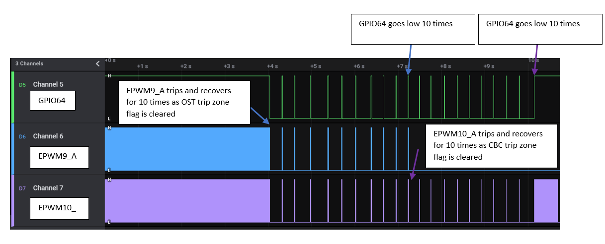
The TZ-Event is defined such that ePWMxA will undergo a One-Shot Trip and ePWMyA will undergo a Cycle-By-Cycle Trip.
The difference could be seen in the waveform generated as shown below. We can see that the for OSHT, as long as we kept clearing the flag (i.e. for 10 times) it recovered. Once loop exits, it goes into permanent trip state.
For CBC as observed at the end, after exiting the loop, it recovers from trip state and goes to active state.
External Connections
- For AM263x-CC:
- GPIO48 is connected to GPIO122
- EPWM9_A and EPWM1_A pin can be connected to an oscilloscope to view the waveform.
- For AM263x-LP:
- GPIO11 is connected to GPIO12
- EPWM9_A and EPWM1_A pin can be connected to an oscilloscope to view the waveform.
AM263X-CC or AM263PX-CC
When using AM263x-CC with TMDSHSECDOCK (HSEC180 controlCARD Baseboard Docking Station)
- Connect HSEC Pin 52 to HSEC Pin 72
- Connect FSI header (on ControlCard) pin 8 to scope for epwm9_A
- Connect HSEC Pin 53 to scope for epwm1_A
AM263X-LP or AM263PX-LP
- Connect boosterpack header J1/J3 pin 7 to J2/J4 pin 18
- Connect boosterpack header J6/J8 pin 75 to scope
- Connect J2/J4 pin 37 to scope
Supported Combinations
| Parameter | Value |
| CPU + OS | r5fss0-0 nortos |
| Toolchain | ti-arm-clang |
| Board | am263x-cc, am263x-lp |
| Example folder | examples/drivers/epwm/epwm_trip_zone |
Steps to Run the Example
- When using CCS projects to build, import the CCS project for the required combination and build it using the CCS project menu (see Using SDK with CCS Projects).
- When using makefiles to build, note the required combination and build using make command (see Using SDK with Makefiles)
- Establish connections as mentioned in External Connections section
- Launch a CCS debug session and run the executable, see CCS Launch, Load and Run
- When the trip input TZ is high, 2 EPWMs generate PWM waveforms.
- When trip input is pulled low , 2 EPWMs gets tripped.
See Also
EPWM
Sample Output
Shown below is a sample output when the application is run,
EPWM Trip Zone Test Started ...
TZ OST interrupt hit 1 times!!
TZ OST interrupt hit 2 times!!
TZ OST interrupt hit 3 times!!
TZ OST interrupt hit 4 times!!
TZ OST interrupt hit 5 times!!
TZ OST interrupt hit 6 times!!
TZ OST interrupt hit 7 times!!
TZ OST interrupt hit 8 times!!
TZ OST interrupt hit 9 times!!
TZ OST interrupt hit 10 times!!
TZ CBC interrupt hit 1 times!!
TZ CBC interrupt hit 2 times!!
TZ CBC interrupt hit 3 times!!
TZ CBC interrupt hit 4 times!!
TZ CBC interrupt hit 5 times!!
TZ CBC interrupt hit 6 times!!
TZ CBC interrupt hit 7 times!!
TZ CBC interrupt hit 8 times!!
TZ CBC interrupt hit 9 times!!
TZ CBC interrupt hit 10 times!!
EPWM Trip Zone Test Passed!!
All tests have passed!!
EPWM Trip Zone waveform
 1.8.20