Introduction
This examples demonstrates periodical triggering of conversion on ADC1 by EPWM0
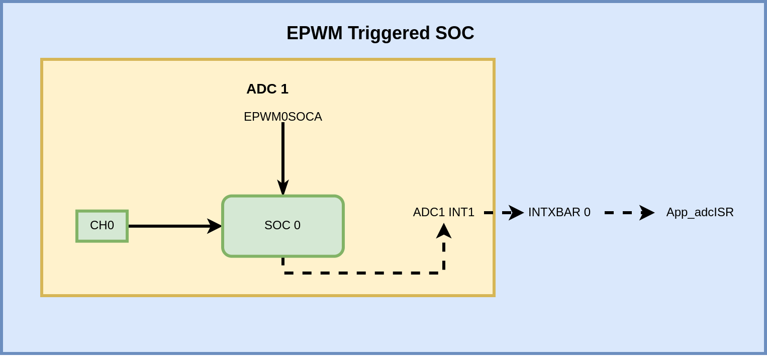
Example Block diagram
SOC Configurations
- SOC 0 trigger is set by EPWM0SOCA
- Samples on ADC1 Channel 0
Interrupt Configurations
- ADC1INT1 source is set to EOC/SOC0
- INTXBAR0 is set to ADC1INT1.
ISR App_adcISR
- Reads the SOC0 result.
- Clears ADC1INT1 flag
External Connections
AM263Px-CC E2 or AM263x-CC E2 or AM261x-SOM E1
- feed analog input on ADC 1 Channel 0 - HSEC connecter pin - 12
AM263x-CC E1
- feed analog input on ADC 1 Channel 0 - HSEC connecter pin - 18
AM263Px-LP or AM263x-LP or AM261x-LP
- feed analog input on ADC 1 Channel 0 - J1/J3 Pin - 24
Watch Variables
- gAdc1Result0 : the array holds the sampled values of the ADC 1 Channel 0
Supported Combinations
| Parameter | Value |
| CPU + OS | r5fss0-0 nortos |
| Toolchain | ti-arm-clang |
| Board | am263x-cc, am263x-lp |
| Example folder | examples/drivers/adc/adc_soc_epwm/ |
Steps to Run the Example
- When using CCS projects to build, import the CCS project for the required combination and build it using the CCS project menu (see Using SDK with CCS Projects).
- When using makefiles to build, note the required combination and build using make command (see Using SDK with Makefiles)
- Establish connections as mentioned in External Connections section
- Launch a CCS debug session and run the executable, see CCS Launch, Load and Run
- Using watch variables, view the ADC conversion results.
- View the ADC conversion results in UART console logs
See Also
ADC
Sample Output
Shown below is a sample output when the application is run,
ADC Soc EPWM Test Started
ADC 1 channel 1 output:
128
128
128
128
128
128
128
128
128
128
128
ADC Soc EPWM Test Passed
All tests have passed!!
 1.8.20