AM263x MCU+ SDK  09.01.00
Understanding the bootflow and bootloaders

Introduction

This section is aimed at explaining what a bootloader is, why is it needed and details regarding the bootloader and bootflow used in the MCU+SDK.

What Is Bootloader?

Generally speaking, bootloader is a piece of software / firmware that runs as soon as you power on an SoC. A bootloader's main duty is to start the subsequent pieces of software, such an OS, a baremetal application or in some cases another bootloader. When it comes to embedded, the bootloader is usually closely tied with the underlying SoC architecture. The bootloader is usually stored in a protected, non-volatile on-chip memory. Typically the bootloader performs various hardware checks, initializes the processor and configures the SoC registers etc. Since the primary aim of the bootloader is to load the next piece of software, it needs to communicate to the external world to receive this firmware/application image. This can be over a number of protocols - USB, UART, SPI, I2C, External Flash, Internal Flash, SD Card, Ethernet, CAN etc. Bootloader is also a key component in embedded security. Hardware Root-of-Trust is usually passed onto the bootloader and is passed on down the line.

Note
In devices supported by MCU+SDK, the first stage bootloader is burned into read-only memory of the device and is considered as device firmware / ROM. Mostly in MCU+SDK when we say "bootloader" we are referring to the secondary bootloader, or the SBL

Multi-Stage Bootloader

As mentioned earlier, sometimes the bootloader would be loading another bootloader which can load another one and so on. This is usually the case in advanced SoCs, and there are various reasons for this. The first bootloader is usually kept on secure, read-only memory for security reasons and to have a known state always before application software starts. It makes sense then to keep this bootloader simple and let it do only the bare minimum configuration required. This secondary bootloader can be complex and configurable to suit the needs of the application. This can also be updated easily compared to the first stage bootloader. In fact for the devices in MCU+SDK, we have a two-stage bootloading - the first stage bootloader is called ROM Bootloader (RBL) and the second stage bootloader is called Secondary Bootloader (SBL).

Multi-Core Bootloading

Multi-core bootloading is almost always a follow up when there is a multi-stage bootloading. In this case the first bootloader technically might not be even aware of the other cores, it will just boot the next stage bootloader and this second stage bootloader will take care of the complex bootloading on the different cores.

Loading a multi-core application is slightly more complicated than loading a single core application. There would be concerns regarding image preparation, shared memory access, and so on. Mostly there would be a particular format in which the individual core images are created, and then they may/may not be concatenated into a single image for SBL to load. Whatever format the application image is in, the SBL should be aware of it so that it can parse and load the image correctly.

Bootloading in MCU+SDK

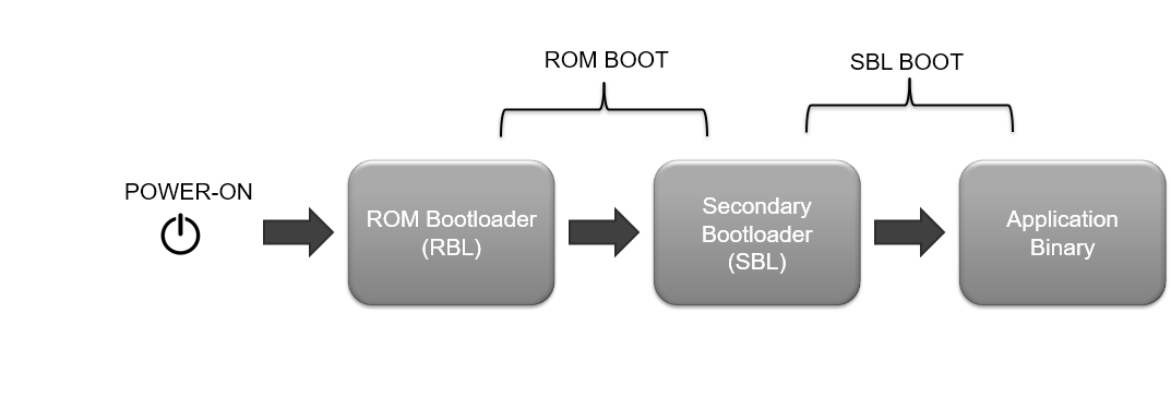
In the MCU+SDK, the bootflow takes place mainly in two steps after you power ON the device

  • ROM boot, in which the ROM bootloader boots a secondary bootloader or an SBL
  • SBL boot in which the secondary bootloader boots the application

ROM Boot

The RBL or ROM Bootloader is stored in read-only memory and is almost considered as part of the SoC. The details regarding the RBL and ROM Boot is out of scope for this user guide. Please refer to the Technical Reference Manual of the device for more details. But basically the ROM expects an x509 signed binary image of the secondary bootloader to be provided for boot.

  • As soon as the board is powered ON, the ROM bootloader or RBL starts running. The RBL is the primary bootloader.
  • Depending on which boot mode is selected, the RBL will load the secondary bootloader or SBL from a boot media (OSPI flash, SD card or via UART).
  • Rest of the booting is done by the SBL.
  • The RBL expects the image it boots (SBL in our case) to always be signed as mentioned above. Refer Booting Tools for more information on signing scripts.

The x509 template for ROM looks something like this:

[ req ]
distinguished_name = req_distinguished_name
x509_extensions = v3_ca
prompt = no
dirstring_type = nobmp
[ req_distinguished_name ]
C = US
ST = SC
L = New York
O = Texas Instruments., Inc.
OU = SITARA MCU
CN = Albert
emailAddress = Albert@gt.ti.com
[ v3_ca ]
basicConstraints = CA:true
1.3.6.1.4.1.294.1.1=ASN1:SEQUENCE:boot_seq
1.3.6.1.4.1.294.1.2=ASN1:SEQUENCE:image_integrity
1.3.6.1.4.1.294.1.3=ASN1:SEQUENCE:swrv
[ boot_seq ]
certType = INTEGER:1
bootCore = INTEGER:16
bootCoreOpts = INTEGER:0
destAddr = FORMAT:HEX,OCT:70002000
imageSize = INTEGER:199488
[ image_integrity ]
shaType = OID:2.16.840.1.101.3.4.2.3
shaValue = FORMAT:HEX,OCT:1d1b24e6487709f007d87c8b2b593abf1853a82a99a54650de85f40ddc7b5ae4558a68e49ea3668732ea34ff4bcf76cc73e4e354a3b8128726843c71b05c4168
[ swrv ]
swrv = INTEGER:1

Depending on the device type, these are the validation requirements for ROM:

Validation for Device Types
  • For ROM to accept any image to boot, there are some restrictions in the image preparation

Preparing the SBL for boot

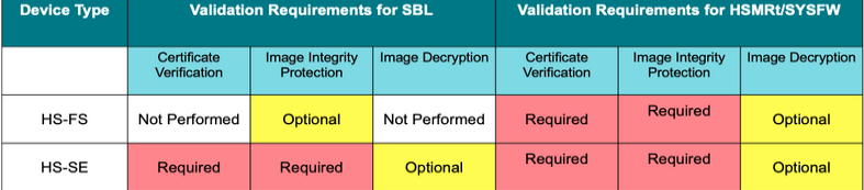
The SBL is like any other application, created using the same compiler and linker toolchain. It is an example implementation rather than a deliverable. It is customizable by users, but must adhere to the requirements by RBL which is a constant as mentioned above. However the steps to convert the application .out into a bootable image are different for SBL as listed below:

  • Other special factors for SBL application are listed below
    • The linker command file for SBL has to place vectors at address 0x70002000 and this is the entry point for the SBL.
    • Nothing should be placed in ATCM or BTCM
    • Currently, the region 0x70002000 to 0x70040000 is used by the SBL code, data, stack, etc.
  • After building, the SBL application .out file is first converted to a binary format .bin using the TI ARM CLANG objcopy tool.
    • This copies the loadable sections from the .out into a binary image stripping all symbol and section information.
    • If there are two loadable sections in the image which are not contiguous then objcopy fills the gaps with 0x00.
    • It is highly recommended to keep all loadable sections together within a SBL application.
  • This .bin file is then signed using the Signing Scripts to create the final .tiimage bootable image.
    • The .tiimage file extension is kept to separate the SBL boot image from a normal application image
    • The rom_degenerateKey.pem is used for this.
    • This is a ROM bootloader requirement and is needed even on a non-secure device.
    • The signing tools take the .bin file
  • The SBL communicates with ROM to get the HSMRt (TIFS-MCU) loaded on the HSM. This firmware provides various foundational security services. For HS-FS ,this can be found at source/drivers/hsmclient/soc/am263x/hsmRtImg.h. For HS-SE devices, more information can be found at MySecureSW. For integrating HSM RunTime with SBL, the following should be taken care of:
    • HSMClient should be initialized and registered.
    • HSMRT (TIFS-MCU) image signed appropriately should be available. For HS-FS, this is already part of the SDK, for HS-SE, this can be compiled with TIFS-MCU package (available on MySecureSW)
  • Depending on the device type for which we build the SBL, there will be certain prefixes to the .tiimage extension like so:
    • HS-FS device:
      • sbl_xxx.release.tiimage [No prefix before .tiimage, plain image]
    • HS-SE device:
      • sbl_xxx.release.hs.tiimage [hs prefix before .tiimage]
  • Note that if we just mentioned hs it is meant for HS-SE device.
  • The .tiimage file can then be flashed or copied to a boot image using the Flashing Tools

TIIMAGE

SBL Boot

  • An SBL typically does a bunch of SOC specific initializations and proceeds to the application loading.
  • Depending on the type of SBL loaded, SBL looks for the multicore appimage (refer Booting Tools for more on multicore appimage) of the application binary at a specified location in a boot media.
  • If the appimage is found, the multicore appimage is parsed into multiple RPRCs. These are optimized binaries which are then loaded into individual CPUs.
  • Each RPRC image will have information regarding the core on which it is to be loaded, entry points and multiple sections of that application binary
  • The SBL uses this information to initialize each core which has a valid RPRC. It then loads the RPRC according to the sections specified, sets the entry points and releases the core from reset. Now the core will start running.

SBL BOOT

  • Now, as mentioned above, to boot an application with SBL it has to be specially prepared after it's compiled.

Preparing the application for boot

Note
To see the exact sequence of steps in which applications and secondary bootloader (SBL) are converted from compiler generated .out files to boot images, see the makefile makefile_ccs_bootimage_gen that is included in every example and secondary bootloader (SBL) CCS project.
If you are using makefile based build, then see the file named makefile in the example folder.

Shown below are the different steps that are done to convert the compiler+linker generated application .out into a format suitable for flashing and booting

  • For each CPU, the compiler+linker toolchain is used to create the application .out "ELF" file which can be loaded and run via CCS
  • The below "post build" steps are then used to convert the application .out into a "flash" friendly format
    • For each CPU, out2rpc is used to convert the ELF .out to a binary file containing only the loadable sections. This is called a RPRC file.
    • multiCoreGen is then used to combine all the RPRC files per CPU into a single .appimage file which is a concatenation of the individual CPU specific RPRC files.
  • This .appimage is then flash to the board.

Post build steps

Flashing the application for boot

  • Once the application images (.appimage) is created one needs to copy or flash these to a supported boot media so that the application can start executing once the SOC is powered ON
  • When flashing the application we also need to flash a bootloader or SBL image.
  • See Flashing Tools for detailed steps that are done to flash a user application

Booting the application

After a SBL and application image is flashed, shown below is the high level boot flow, after the SOC is powered on.

HIGH LEVEL BOOTFLOW

Secure Boot

In secure device variants, there are slight differences in the bootflow. For details on secure boot, please refer Enabling Secure Boot

PBIST For 200MHz and 400MHz R5F Core Variants

pBIST (parallel Built-In Self-Test) can be performed for both 200MHz and 400MHz part numbers by including the instance of mcu_bist in the sys-config for the bootloader examples. By default it's enabled only for bootloader sbl-sd. For 400 MHz part numbers ROM performs pBIST on R5FSS0 Memories and L2 Memory - Bank-0 and Bank-1. But due to ROM limitation this test is not done by ROM for 200 MHz part numbers. The mcu_bist instance can be added or removed on the basis of use-case. pBIST is perfromed only on L2 memory - three banks (Bank-1,Bank-2,Bank3 (not on Bank-0)) and R5FSS1 TCM Memories. Please refer below for more information.

Note
Important Information:
  • pBIST is a destructive test and cannot be run on active memories.
  • Perform pBIST on specific sections of RAM and Subsystem 1 TCM, excluding active areas.
  • SBL code must resides in the 0th bank of L2 memory to perform pBIST on the other three banks, as mcu_bist instance will run pBIST on L2 memory - Bank 1, Bank 2, Bank 3. The mcu_bist instance can be added for sbl_qspi as it resides in Bank-0. If SBL resides in banks other than Bank-0, the pBIST setup must be updated with the specific memories.
Step Description
1 SBL Startup
  • Ensure SBL is installed correctly on the target device
  • Power on or reset the device to initiate SBL startup
2 Efuse Bit Detection
  • During SBL startup, efuse bits will be checked
  • If 200 MHz variant is detected, proceed to Step 3
  • Otherwise, skip to the next startup process
3 pBIST Execution
  • Initiating pBIST if 200 MHz variant is detected
  • pBIST performed on specific sections of RAM and Subsystem 1 TCM memories, excluding active areas i.e., Subsystem 0 TCM memories
  • SBL code resides in the 1st bank of L2 memory (Bank-0); So pBIST is performed on the other three banks of L2 memories.

In software workaround, pBIST is perfromed only on L2 memory - three banks (Bank-1,Bank-2,Bank3 (and not on Bank-0)) and R5FSS1 TCM Memories.
User can perfrom pBIST on the remaining L2 Memory bank-0 and R5FSS0 TCM memories on their own by following the steps given below: The following table provides an overview of the steps to perform pBIST on RFSS0 TCM and L2 Memory Bank-0:

Step Description
1 Use the SDL example of pBIST that utilizes the SDL pBIST library.
2 Set up the test environment to specify L2 bank-0 and R5FSS0 TCM memories.
3 Update the SBL to be loaded on other memory banks (excluding bank 0).
4 The SBL will load the application on the RFSS1 core, which will run pBIST on the remaining L2 bank-0 and R5FSS0 TCM memories.
5 Once pBIST is completed, the device will be reset to proceed with normal booting.

By following these steps, you can perform pBIST on the specified L2 memory bank-0 and R5FSS0 TCM memories, ensuring proper self-testing, and allowing the device to boot normally afterwards.

• The pBIST can be run for both 200 MHz and 400 MHz part variants. To run the pBIST user can include mcu_bist instance for the specific bootloader in the syscfg.
• By default it's enabled only for bootloader sbl-null.
• The software workaround described in this user guide for L2 Memory Bank-0 and R5FSS0 TCM memories is specifically designed to address the ROM errata affecting 200 MHz R5F core variants.
• The pBIST procedure performed during the SBL startup helps mitigate the limitations imposed by the ROM.
• It is important to ensure that the SBL and associated software are correctly installed and configured on the target device for the workaround to function effectively.

To know more about pBIST and overall SDL support for pBIST, please take a look at PBIST

Deep Dive into SBLs

The SBL is like any other example of the SDK. They use the bootloader library APIs to carry out the bootloading process. Depending on the boot media from which we load the application binary, we have multiple SBLs like sbl_ospi,sbl_uart etc. A bare minimum SBL called the sbl_null is also included which aids the users to load their applications via CCS. Here are some details regarding those.

SBL NULL

  • The sbl_null is a secondary bootloader which doesn't load any application binary, but just does the SOC initialization and puts all the cores in WFI (Wait For Interrupt) mode.
  • This is supposed to be a "development form" bootloader which should be used only during initial development.
  • The other method is using NO-BOOT/DEV-BOOT boot modes of the devices and using GEL scripts to initialize the SoC via debugger. The application binaries can then be side-loaded. ROM is not involved in this case. The sbl_null is an alternative to this process.
  • This is referred to as the SOC initialization binary, refer SOC Initialization using the Binary Flashed in QSPI memory for more on this.

SBL QSPI

  • The sbl_qspi is a secondary bootloader which reads and parses the application image from a location in the QSPI flash and then moves on to core initialization and other steps
  • To boot an application using the sbl_qspi, the application image needs to be flashed at a particular location in the QSPI flash memory.
  • To flash an application (or any file in fact) to a location in the QSPI flash memory, follow the steps mentioned in Basic steps to flash files

SBL UART

  • The sbl_uart is a secondary bootloader which receives the multicore appimage via UART, stores it in memory and then does the parsing, core initialization etc.
  • To boot an application using the sbl_uart, you can refer to UART Bootloader Python Script subsection. Detailed steps on the usage is mentioned in the same subsection.

SBL CAN

  • The sbl_can is a secondary bootloader which needs to be flashed in QSPI Flash.
  • The sbl_can receives the multicore appimage via CAN, stores it in memory and then does the parsing, core initialization etc.
  • To boot an application using the sbl_can, you can refer to CAN Bootloader Python Script subsection.

SBL SD

  • The sbl_sd is a secondary bootloader which reads the application image file from the SD card and then moves on to core initialization and other steps
  • To boot an application using the sbl_sd, the application image needs to be copied to the SD card as a file named "app"
  • Similarly you can copy any appimage file to the SD card and rename in the SD card as "app" so that the SBL can pick it up.
  • Currently the sbl_sd reads the full appimage file into an MSRAM buffer and then parses the multicore appimage. Because of this reason appimages higher than ~512 KB in size can't be booted by sbl_sd as of now.
  • To boot and appication using sbl_sd, you can refer to SBL SD subsection.

Additional References

See also these additional pages for more details and examples about the boot flow,