|
IO-Link Master
1.09.00
|


|
|
IO-Link Master
1.09.00
|
|
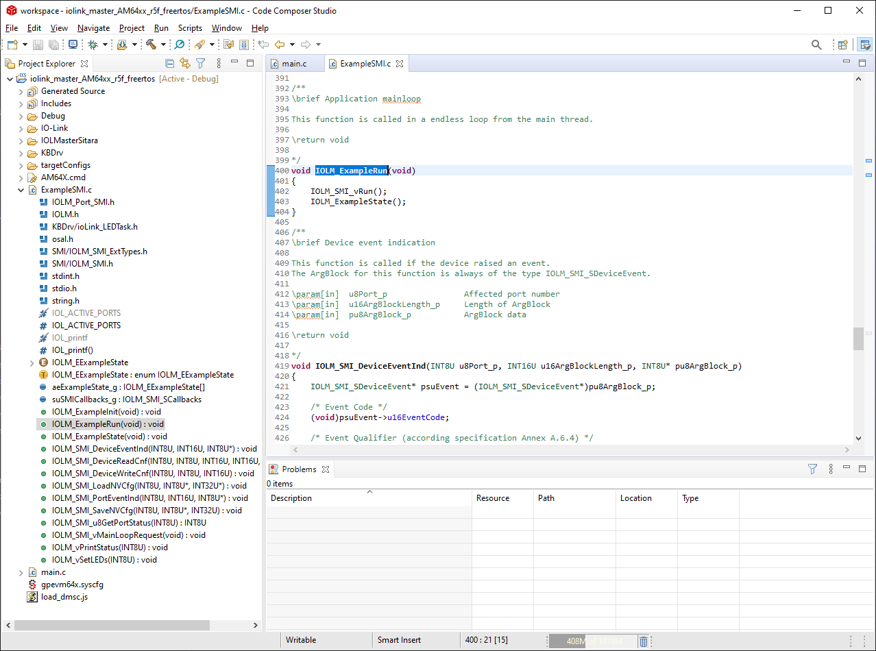
This example runs the Master stack functions in its own seperate task. This task initializes
all needed interfaces and then executes the IOLM_exampleRun() function in an endless loop.
The IOLM_exampleRun() function is located in the ExampleSMI.c file,
where it is possible to add or modify code to fit the desired environment.
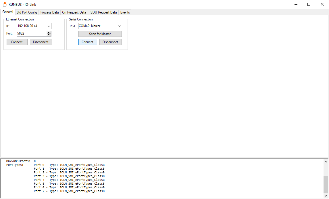
The IO-Link Master GUI can be used to connect to the IO-Link Master's
Standardized Master Interface (SMI) via usb, set up configuration parameters,
read status information and communicate with attached IO-Link devices.
The Master has to be connected to the UART USB port for the AM243x EVM or to XDS debug port for the AM243x Launchpad.
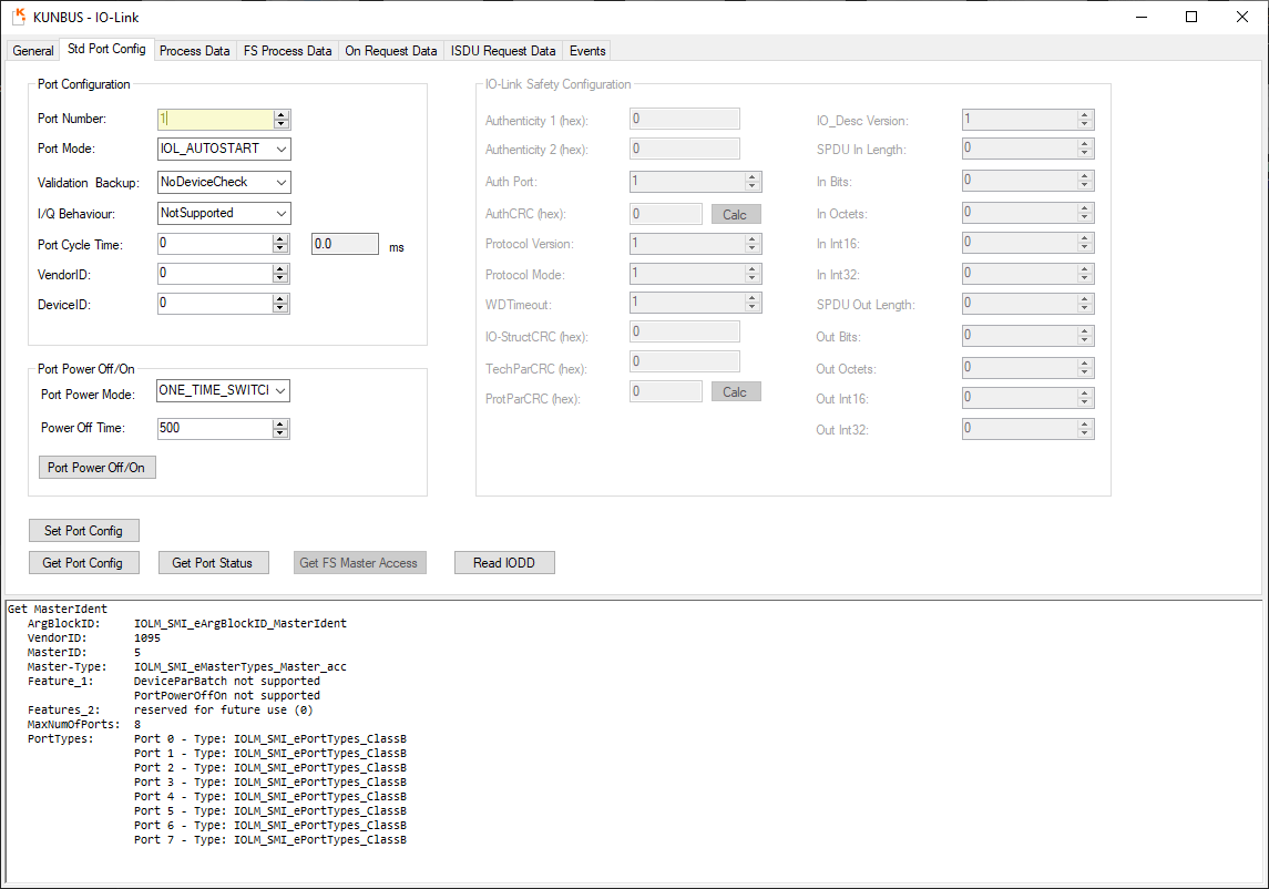
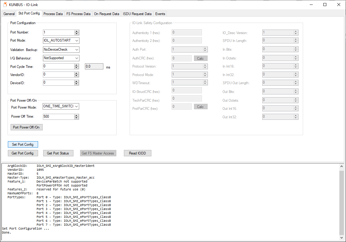
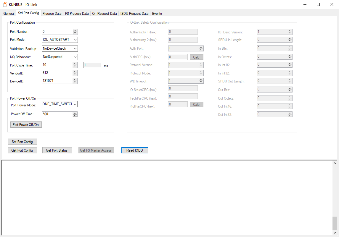
In the Std Port Config tab the configuration and status of the Master's eight ports
can be read and changed.
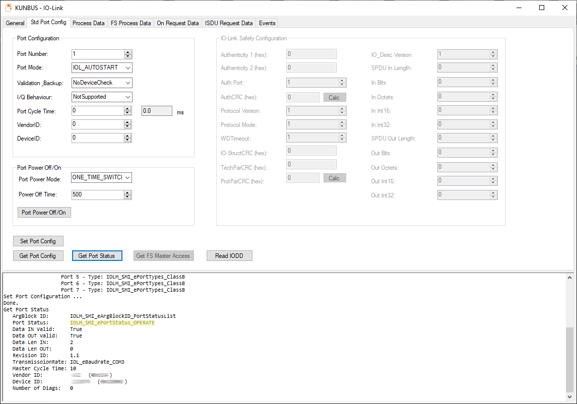
You can retrieve the Master's current port configuration and port status
by clicking the corresponding buttons.
The default setting sets all ports except the first one (port number: 0) to DEACTIVED.
Port 0 is by default set to IOL_AUTOSTART, which starts an auto-detect-sequence.
For more details on port modes see the section Set up IO Link Port
and the IO-Link Specification v1.1.2.
After changing the Master's port configuration it will be saved in its internal
non-volatile memory and remain even after restarting or turning it off.
To connect a Device to a certain port, its mode has to be changed to IOL_AUTOSTART.
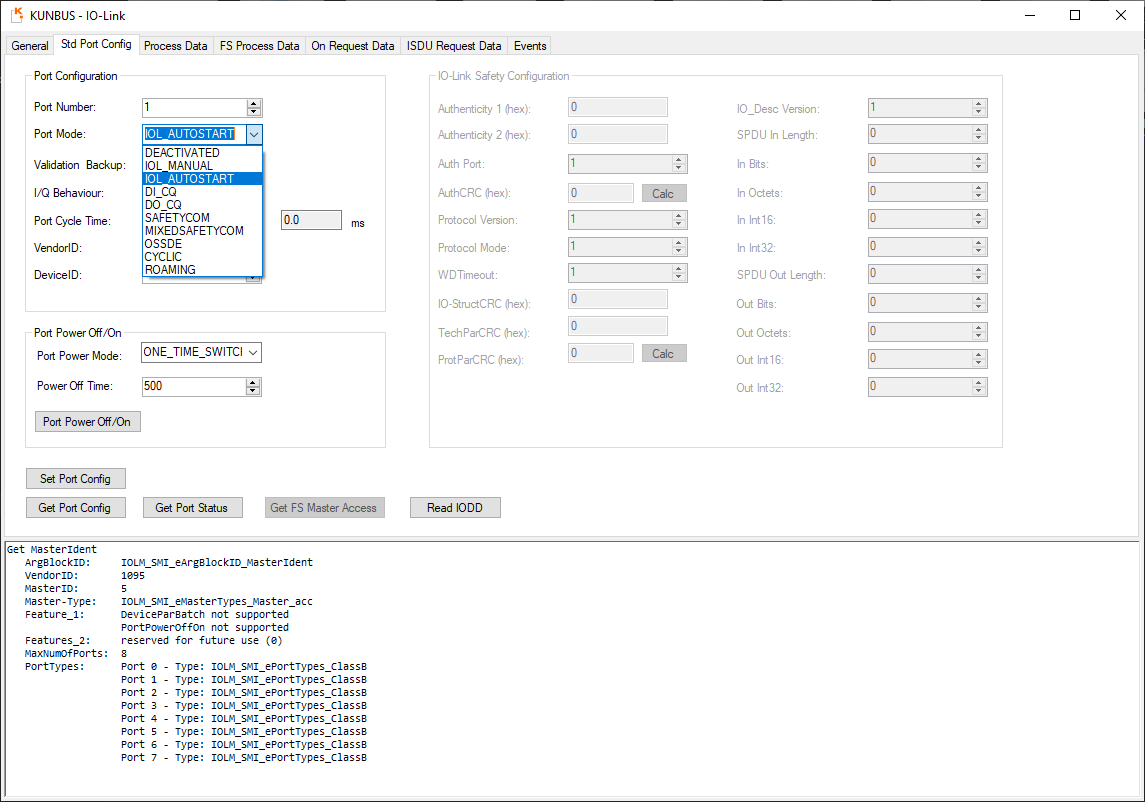
If a Device is connected and the communication is established, the port's status changes
from DEACTIVED to OPERATE.
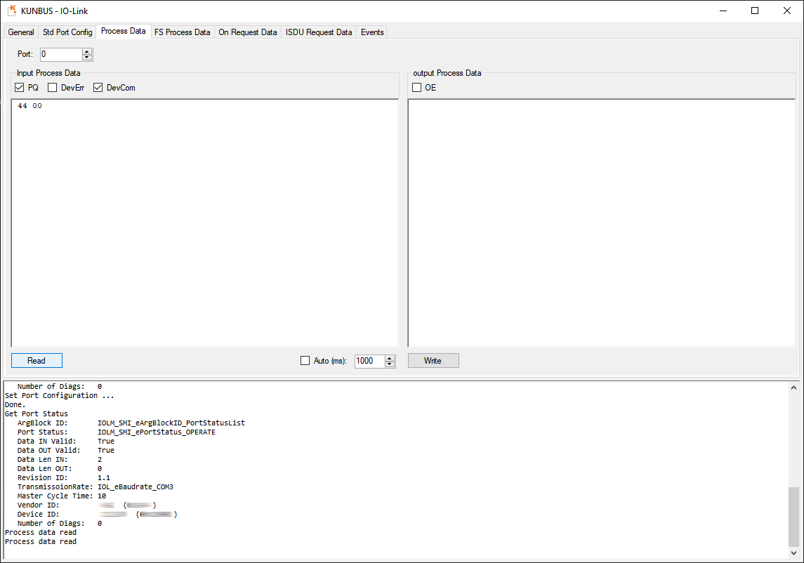
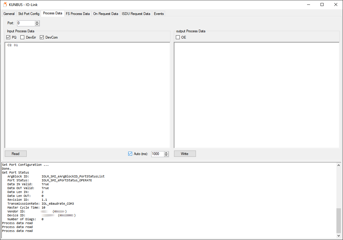
To read Process Data from a Device go to the Process Data tab
and set Port: to its corresponding port number.
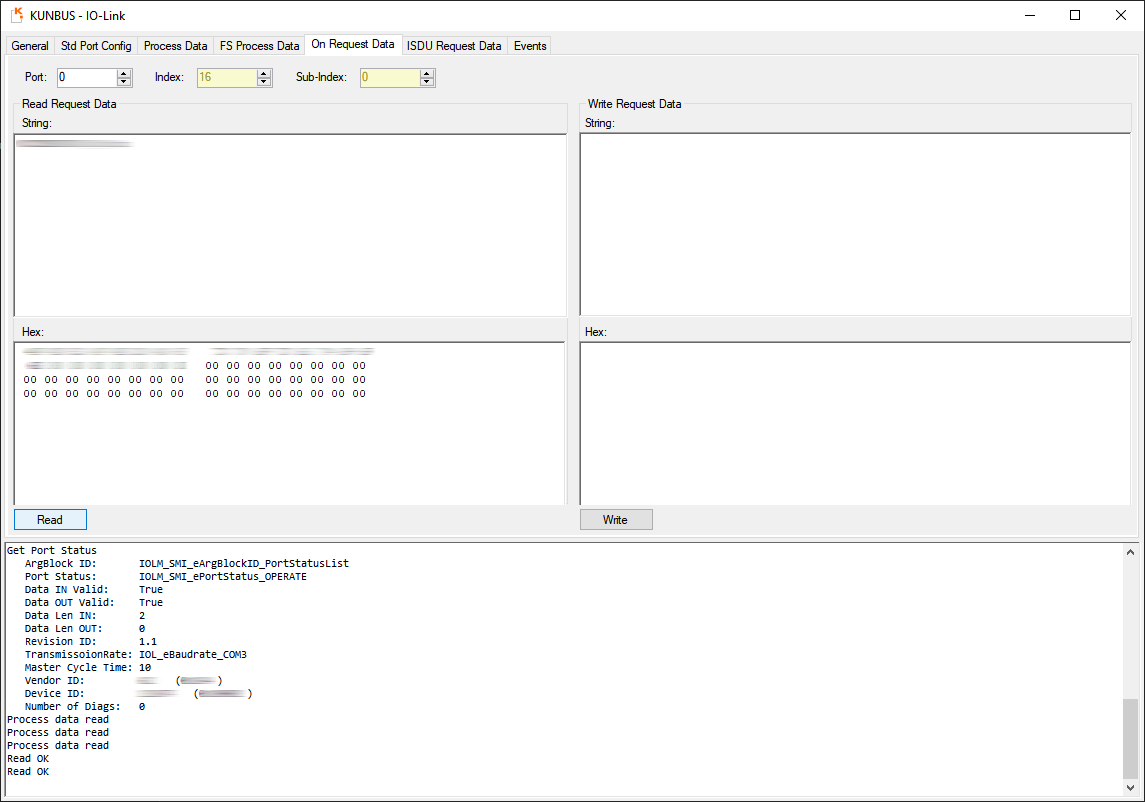
In the On Request Data tab you can request Indexed Service Data Units (ISDUs)
from the Device or send ISDUs to the Device.
For more information on ISDUs see the IO-Link Specification v1.1.2.
As an example, you can get the vendor name by setting the Index to 16
and leaving the Sub-Index set to 0.
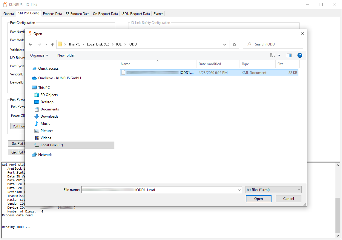
It is possible to import IO Device Description (IODD) files for ones connected Devices
in the Std Port Config tab. This makes it easier to read and set Device parameters.
For more information on IODD files see the IO-Link Specification v1.1.2 and the IODDFinder.
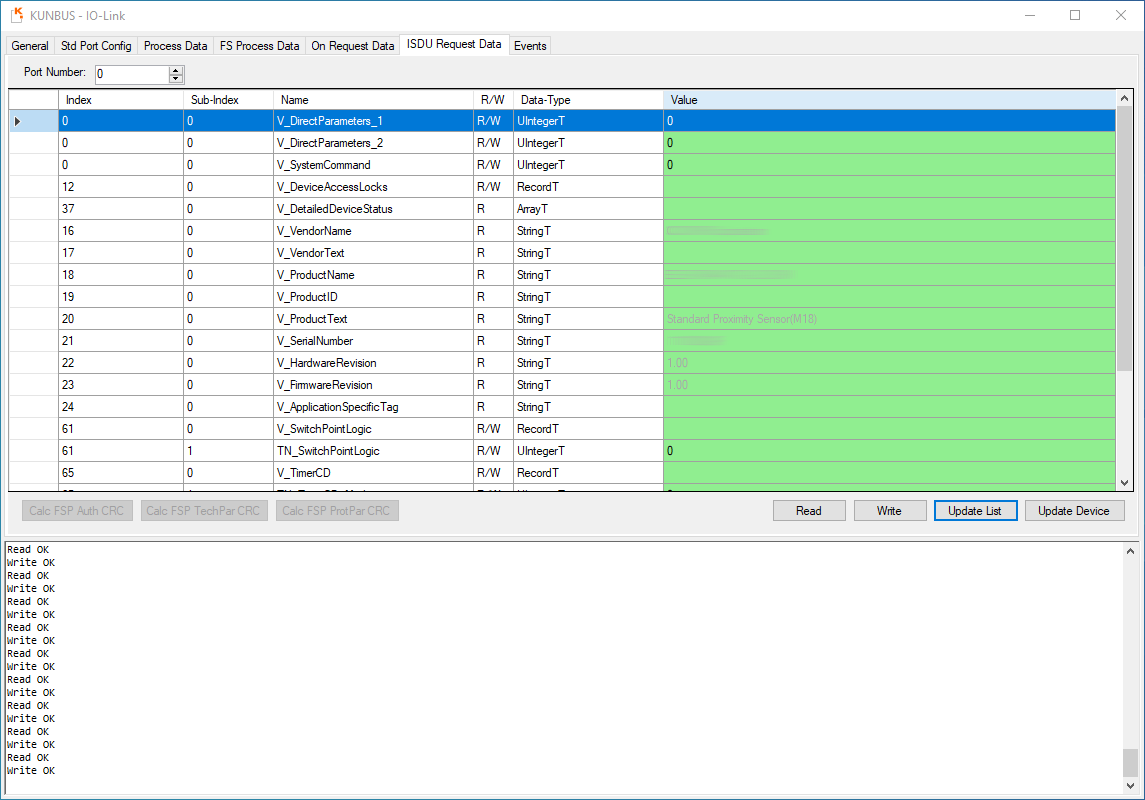
Values which aren't read-only can be changed and then sent to the Device by pressing the Write button.
 1.8.18