Introduction
- Normally, when running a application, the application code is first copied to RAM by bootloader and then code executes from RAM.
- XIP or eXecute In Place allows a application to execute part of the code from flash without having to copy to RAM.
- Advantage is, this allows users to have a larger code size limited by flash size rather than limited by RAM size.
- Disadvantage is,
- The flash memory is typically slower (~300MB/s bandwidth) vs RAM memory ( > 1600 MB/s),
- Due to this, execution speed, esp when code is not cached in the CPU cache, will be slower as compared to when executing from RAM.
- However in some situations it is needed to execute code from flash for non-real time, non high performance code.
- XIP allows to do this.
Additional References
See also these additional pages for more details and examples about XIP,
Pre-requisites
- The flash memory should be visible to the CPU, in "direct access mode (DAC)" i.e memory mapped mode.
- Here the contents of the flash can be read as any other memory region.
- This typically is a "read-only" memory
- The secondary bootloader needs to enable flash at highest throughput mode in this DAC mode, before booting the application.
- The application entry point, interrupt vectors and initial code upto
main() should still execute from RAM. After main() the code can execute from flash.
Enable XIP for a application
To enable XIP for a application, below changes need to be done,
- Enable cache for the XIP flash region. This is need to get better performance for the XIP execution
- On R5F, this is done by adding a MPU entry for region
0x60000000 of size 256MB. This can be done via SysConfig.
- If a CPU, say M4F, does not have any cache, then recommend to not use XIP for that CPU.
- A sample MPU setting on AM64x, AM243x SOC done via SysConfig is shown below.
- Make sure to enable code execution, and cache for this region.
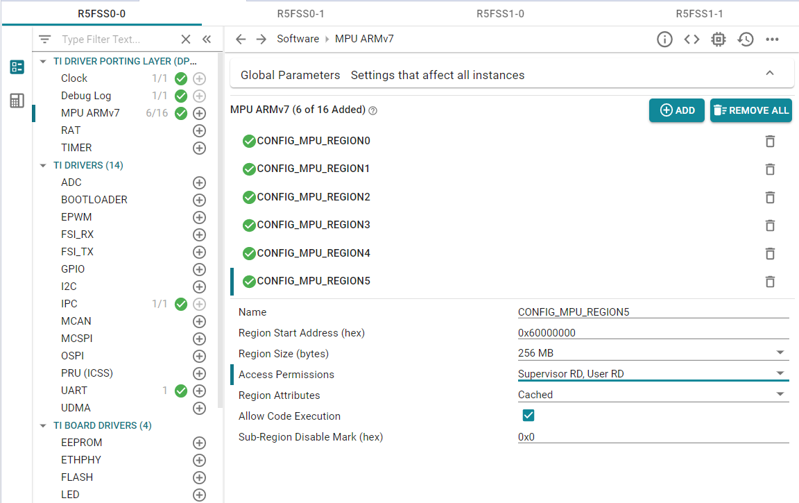
Flash section in R5F MPU
- Update the linker command file to re-direct required
.text and .rodata sections to FLASH region as shown below SECTIONS {
...
GROUP {
.text: {} palign(8) /* This is where code resides */
.rodata: {} palign(8) /* This is where const's go */
} > FLASH
...
}
MEMORY
{
...
FLASH : ORIGIN = 0x60100000 , LENGTH = 0x80000
...
}
- The same process can be repeated for multiple CPUs if needed, only make sure the
FLASH defined in MEMORY { ... } for the linker command files of each CPU are non-overlapping.
- NOTE, when multiple CPUs run using XIP, the overall available flash bandwidth get split across multi-CPUs. So the overall performance will degrade vs using single CPU in XIP mode. However, functionally nothing restricts such a mode of operation.
- As part of post build step, one extra step is run as compared to non-XIP case, as listed below
xipGen tool is used to split the application into non-XIP and XIP sections
- The file containing XIP sections is additionally flashed to the flash using the special
flash-xip command passed to the flash writer
- NOTE, the secondary bootloader remains exactly the same when running applications in XIP or non-XIP mode.
- For all the SDK examples
- The linker command is updated to include the
FLASH memory segment. The code/rodata section are NOT re-directed to FLASH by default though, unless mentioned otherwise in the example.
- XIP post-build steps are always invoked as part of application post build. Invoking these steps even though there is no XIP section has no side effect.
- The default flash writer config file has the flashing command needed to flash the XIP sections. Again, if XIP sections are not present there is no side effect on normal non-XIP operation.
- Thus, all one needs to do to enable XIP is
- Add a MPU/MMU entry to mark the flash region as executable + cached
- And update the linker command to mark the code/rodata sections as
FLASH instead of RAM.
- Rest of the steps remain exactly the same as non-XIP case.
Debugging XIP applications
- XIP applications can not be loaded via CCS, hence to debug a XIP application one needs to always flash and run the application and then "load symbols" via CCS to debug the application
- Another alternative is develop and debug the application with all code in "RAM" and then just update the linker command to use "FLASH" and do the final test or debug with application in XIP mode.
- The CCS option to load symbols is shown below,
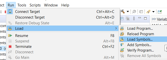
CCS Load Symbols
- Normal "SW" breakpoints in CCS wont work for code in flash, and "HW" breakpoints should be used.
- To put a breakpoint CCS needs to write a special instruction at the point in code,
- However since the flash memory is "read-only", this will result in a error, hence one should use "HW" breakpoints instead
- Below shows a example of putting a HW breakpoint,
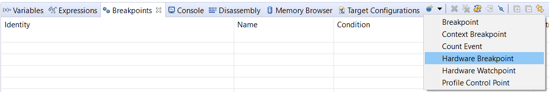
HW Breakpoint
- When prompted enter the function name on which you want the breakpoint to hit.


 1.8.20