A system designer must have a firm grasp on the general system architecture, application, and Bluetooth low energy stack framework to implement a custom Bluetooth low energy application. This section provides indications and guidance on where and how to start implementing a custom application based on information presented in the previous sections (The Application and The Stack) as well as knowledge of TI-RTOS and CC26x2.
Decide what role and purpose the custom application should have. If an application is tied to a specific service or profile, start with that sample application.
A project’s role can be essentially be placed in one of the five (5) categories as described by GAP Roles.
Defining Application Behavior
The Sample Applications will often contain simple TI-RTOS tasks with a barebones messaging system between tasks. For more information on how the application tasks works in general, review The Application.
Directed Advertisements as GATT Server
In BLE5-Stack 1.01.01.00, Privacy is always enabled. Most of the privacy features are handled by the GAP bond manager in the stack. To conserve flash memory, by default, the GAP bond manager does not enable GATT client features. The implication of these disabled GATT client features is that the GAP bond manager will not query the Central Address Resolution characteristic of the remote device.
In order to perform a directed advertisement when the initiator’s address is set to Private Resolvable Address, the peripheral device must read the Central Address Resolution characteristic of its remote device to make sure address resolution is supported. Failure to do so before sending directed advertisements violates the Bluetooth Core Specification Version 5.0.
By default, sample applications such as simple_peripheral does not define GATT_NO_CLIENT and initializes the GATT Client as shown below:
  // Initialize GATT Client, used by GAPBondMgr to look for RPAO characteristic for network privacy
  GATT_InitClient();
Compiler Options
For BLE5-Stack projects, compiler options are defined via .opt files that are
included in the IDE’s TOOLS\defines folder. Each project’s build
configuration will include its very own .opt file.
The predefined symbols in the .opt files are prefixed with a -D, which
is standard commandline prefix notation across all the supported toolchains.
Of the predefined symbols in the .opt files, some of them are configurable
and some are not. See Bluetooth Low Energy Application Configuration Parameters
and Bluetooth Low Energy Stack Configuration Parameters for reference as to which options are
configurable.
The convention to disable a symbol in the .opt files is to put an ‘x’ in
front of the name. For example, to disable power management,
change -DPOWER_SAVING to -DxPOWER_SAVING. It is also possible to disable
a symbol by commenting it out via ‘C - style’ syntax
(e.g. /* -DPOWER_SAVING */)
Linker Options
Linker symbols may need to be set or adjusted at the project level in order to control the memory layout of the generated image. The following procedure describes how to access and modify linker symbols.
CCS
- Open Project Properties
- Navigate to Build -> ARM Linker -> Command File Preprocessing
- Use the buttons highlighted in Figure 50. to add, delete, or edit a linker symbol.
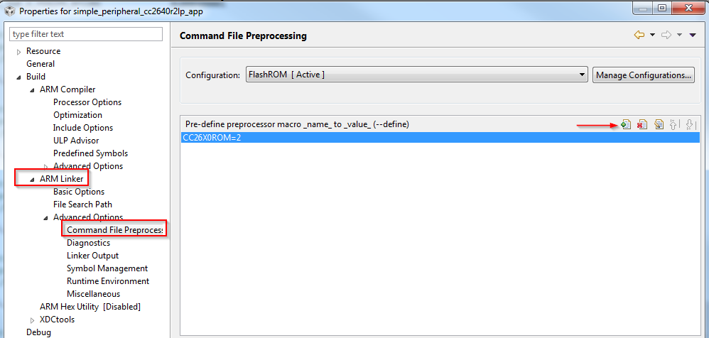
Figure 50. CCS Linker Symbols
IAR
- Open the Project’s Options and select the Linker Category.
- Open the Config tab.
- View the Configuration File symbol definitions box (see Figure 51.).
- Add or edit the preprocessor symbols.
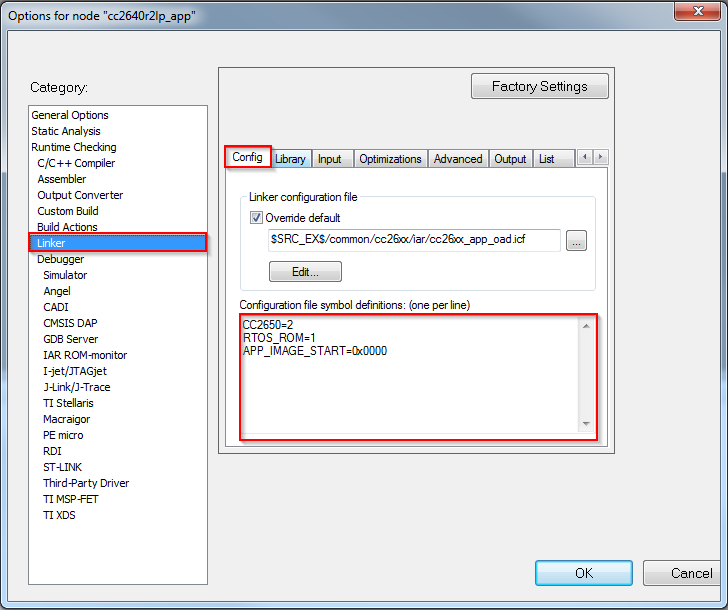
Figure 51. IAR Defined Symbols Box
Creating Additional ICall Enabled Tasks
Warning
TI Recommends limiting the number of ICall enabled tasks due to resource usage. For more information on creating ICall enabled tasks, see Adding ICall RTOS Tasks
The objective of this section is to familiarize the programmer with the process of adding an RTOS task that can communicate with the BLE5-Stack. Tasks call functions within the BLE5-Stack must follow a few additional steps to register with ICall. These details are covered below:
1. Follow all the steps detailed in Tasks to create a TI-RTOS task.
- Modify the task’s init function to register with ICall (explained in ICall Initialization and Registration)
- Modify the task’s main function to pend on
syncEvent(explained in ICall Thread Synchronization)
- Modify number of ICall enabled tasks:
- Increase the following preprocessor defines:
- ICALL_MAX_NUM_TASKS (App)
- OSAL_MAX_NUM_PROXY_TASKS (Stack)
- See Compiler Options for steps on how to change symbols.
Warning
If OSAL_MAX_NUM_PROXY_TASKS and ICALL_MAX_NUM_TASKS do not match, the stack will abort.
- Modify number of ICall entities:
- Increase the following preprocessor defines:
- ICALL_MAX_NUM_ENTITIES (App)
For further description of the above preprocessor defines, please see Table 8.
Using Production Test Mode (PTM)
PTM is a way to pass HCI commands from an external communication protocol to the controller of the BLE5-Stack.
This section provide a brief overview of enabling PTM and an example of how to implement PTM on on a stack library simple_peripheral project using UART as the transfer protocol. The steps shown will be using IAR, however the steps are the same for CCS.
To enable PTM and send the HCI status back via external transport protocol, the application must:
Add NPI to the Application Project
Network Processor Interface (NPI) is utilized to move HCI commands from the various entities in the embedded application. Relevant NPI files will need to be added to the application to enable access for this functionality.
Configure NPI to Receive Commands From Transport Protocol
A transport protocol is used to transfer commands and status between a BLE HCI Tester and the application. NPI currently supports SPI and UART protocols. UART will be used in the example below. NPI by default utilizes a handshake/flow control system to signal when a slave is ready to transmit/receive and when a master is ready to transmit/receive. This feature will be disabled as the functionality is not needed. For more information on NPI see NPI Wiki
Send HCI Commands Using ICall Direct API
The embedded application must intercept the NPI Frame and send the message to the BLE-Stack through the enhanced ICall’s direct message API. To configure NPI to only send messages to the embedded application, the
NPITask_registerIncomingRXEventAppCBfunction is utilized to tell NPI toINTERCEPTmessages and send them to a function which will then utilize ICall Direct API. The ICall HCI Transport Layer (icall_hci_tl.c) will also be added to the project. ICall Direct API for any given HCI command can be translated from an NPI frame viaHCI_TL_SendToStack, defined by the ICall HCI Transport Layer, into a Direct API expected by the BLE-Stack.Explicitly Enable PTM and Configure HCI Transport Layer
On the stack side, the transport layer capability is defined in the
build_config.optfile under theToolsfolder. To enable the transport layer, this file will need to be modified to defineHCI_TL_PTM. The stack can now be notified to enter PTM via theHCI_EXT_EnablePTMCmd()Vendor Specific HCI Command.Configure NPI to Forward Responses to Transport Protocol
Events and status of commands should be sent back to the transport protocol. This is done by registering callback functions with the transport layer which forward the messages to NPI. Once NPI has the messages, it then will send the message to the transport protocol configured.
Stack Project Changes
Preprocessor Defines
These defines are located in the .opt file in the stack’s Tools/defines
folder. Select the .opt that is appropriate to the current build
configuration (FlashROM_Library, etc.). For additional information on adding
ICall Aware Tasks, and the modifications made to the Application and
Stack Projects see
Creating Additional ICall Enabled Tasks.
Add or modify (if it pre-exists) the following preprocessor defines:
...
-DOSAL_MAX_NUM_PROXY_TASKS=4
...
OSAL_MAX_NUM_PROXY_TASKS increases by one to accommodate for an NPI Task to
be created. So this should increase by one based on your appplication’s
current value. The value of 4 here is used as an example.
Enable PTM and Configure HCI Transport Layer
The HCI Transport Layer needs to be configured to use the correct jump table.
On the stack side, the transport layer capabilities is defined in the
build_config.opt file under the Tools folder. By default no
transport layer is included on the stack side to save flash.
In this example, the following modification in build_config.opt
to enable PTM commands:
/* Include Transport Layer (Full or PTM) */
/* -DHCI_TL_NONE Comment this line */
-DHCI_TL_PTM
/* -DHCI_TL_FULL */
The stack must now be rebuilt for the changes to take effect and ensure support for the PTM commands.
Application Project Changes
Preprocessor Defines
These defines are located in the .opt file in the app’s Tools/defines
folder. Select the .opt that is appropriate to the current build
configuration (Release, Debug, etc.).
Add or modify (if it pre-exists) the following preprocessor defines:
...
-DICALL_MAX_NUM_TASKS=4
-DNPI_USE_UART
-DNPI_FLOW_CTRL=0
...
ICALL_MAX_NUM_TASKS increases by one to accommodate for an NPI Task to
be created. So this should increase by one based on your appplication’s
current value. The value of 4 here is used as an example.
NPI_USE_UART enables UART as the transport protocol for NPI.
A transport protocol is used to transfer commands and status between
a BLE HCI Tester and the application. NPI currently supports SPI and UART
protocols.
NPI by default utilizes a handshake/flow control system to signal
when a slave is ready to transmit/receive and when a master is
ready to transmit/receive. For testing purposes,
this functionality isn’t needed and is disabled with NPI_FLOW_CTRL=0.
Adding NPI and ICall HCI TL Files
To add NPI and the ICall HCI TL file to the project, add the following files to your application. Replace <SDK> with your SDK’s file path. You may want to copy these files into the project instead of linking it to prevent unwanted SDK modifications:
<SDK>\source\ti\ble5stack\npi\src\npi_frame_hci.c
<SDK>\source\ti\ble5stack\npi\src\npi_rxbuf.c
<SDK>\source\ti\ble5stack\npi\src\npi_task.c
<SDK>\source\ti\ble5stack\npi\src\npi_tl.c
<SDK>\source\ti\ble5stack\npi\src\npi_tl_uart.c
<SDK>\source\ti\ble5stack\icall\app\icall_hci_tl.c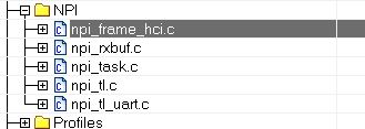
Figure 52. Added Files in NPI Folder (IAR)
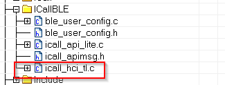
Figure 53. Added File in ICallBLE Folder (IAR)
If not added already, within your application’s project settings add the NPI and ROM (for ICall) include directory to the include search path for the IDE:
<SDK>\source\ti\ble5stack\npi\src
<SDK>\source\ti\ble5stack\npi\src\inc
<SDK>\source\ti\ble5stack\rom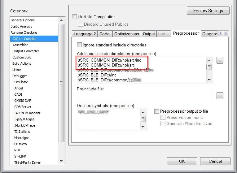
Figure 54. NPI Include Directories (IAR)
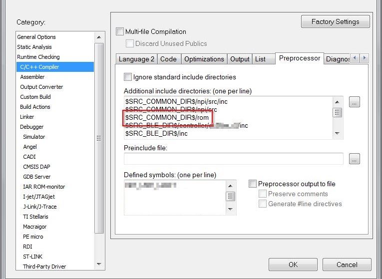
Figure 55. ROM Include Directories (IAR)
Creating the NPI Task in main.c
The following changes are to be made in the Startup/main.c file.
To include the NPI Task into the project, add npi_task.h to main.c
and add NPITask_createTask(ICALL_SERVICE_CLASS_BLE); towards the end of
main() where tasks are being created.
#include "simple_peripheral.h"
#include "npi_task.h"

//...

int main()
{

  //...

  /* Start task for NPI task */
  NPITask_createTask(ICALL_SERVICE_CLASS_BLE);

  /* enable interrupts and start SYS/BIOS */
  BIOS_start();
  //...

}
Set the NPI Task Priority
The NPI task must be set to a proper priority in npi_task.c.
Ideally it should be lower than the stack task, but higher than the GAP task.
This allows commands to interrupt tasks if required.
For this example, the priority of 4 worked perfectly:
//! \brief Task priority for NPI RTOS task
#define NPITASK_PRIORITY 4
Modifying the App File
The following changes are to be made in the application’s .c file.
This example will be provided with the context of simple_peripheral.c.
Refer to the added comments for further information.
Include the following header files:
//...

#include "simple_peripheral.h"

#include "npi_task.h"        // To allow RX event registration
#include "npi_ble.h"         // To enable transmission of messages to UART
#include "icall_hci_tl.h"    // To allow ICall HCI Transport Layer

//...
Add the following function declarations and definitions:
//...

void SBP_handleNPIRxInterceptEvent(uint8_t *pMsg);  // Declaration
static void SBP_sendToNPI(uint8_t *buf, uint16_t len);  // Declaration

//...

 /*********************************************************************
* @fn      SBP_handleNPIRxInterceptEvent
*
* @brief   Intercept an NPI RX serial message and queue for this application.
*
* @param   pMsg - a NPIMSG_msg_t containing the intercepted message.
*
* @return  none.
*/
void SBP_handleNPIRxInterceptEvent(uint8_t *pMsg)
{
  // Send Command via HCI TL
  HCI_TL_SendToStack(((NPIMSG_msg_t *)pMsg)->pBuf);

  // The data is stored as a message, free this first.
  ICall_freeMsg(((NPIMSG_msg_t *)pMsg)->pBuf);

  // Free container.
  ICall_free(pMsg);
}

/*********************************************************************
* @fn      SBP_sendToNPI
*
* @brief   Create an NPI packet and send to NPI to transmit.
*
* @param   buf - pointer HCI event or data.
*
* @param   len - length of buf in bytes.
*
* @return  none
*/
static void SBP_sendToNPI(uint8_t *buf, uint16_t len)
{
  npiPkt_t *pNpiPkt = (npiPkt_t *)ICall_allocMsg(sizeof(npiPkt_t) + len);

  if (pNpiPkt)
  {
    pNpiPkt->hdr.event = buf[0]; //Has the event status code in first byte of payload
    pNpiPkt->hdr.status = 0xFF;
    pNpiPkt->pktLen = len;
    pNpiPkt->pData  = (uint8 *)(pNpiPkt + 1);

    memcpy(pNpiPkt->pData, buf, len);

    // Send to NPI
    // Note: there is no need to free this packet.  NPI will do that itself.
    NPITask_sendToHost((uint8_t *)pNpiPkt);
  }
}
At the end of the initialization function, add the following function calls:
//...

static void SimpleBLEPeripheral_init(void)
{

  //...

  // Intercept NPI RX events.
  NPITask_registerIncomingRXEventAppCB(SBP_handleNPIRxInterceptEvent, INTERCEPT);

  // Register for Command Status information
  HCI_TL_Init(NULL, (HCI_TL_CommandStatusCB_t) SBP_sendToNPI, NULL, selfEntity);

  // Register for Events
  HCI_TL_getCmdResponderID(ICall_getLocalMsgEntityId(ICALL_SERVICE_CLASS_BLE_MSG, selfEntity));

  // Inform Stack to Initialize PTM
  HCI_EXT_EnablePTMCmd();

}

//...
At the end of the process stack message function, add the following:
//...

static uint8_t SimpleBLEPeripheral_processStackMsg(ICall_Hdr *pMsg)
{

  //...

  switch (pMsg->event)
  {
    //...
  }

  // Check for NPI Messages
  hciPacket_t *pBuf = (hciPacket_t *)pMsg;

  // Serialized HCI Event
  if (pBuf->hdr.event == HCI_CTRL_TO_HOST_EVENT)
  {
    uint16_t len = 0;

    // Determine the packet length
    switch(pBuf->pData[0])
    {
      case HCI_EVENT_PACKET:
        len = HCI_EVENT_MIN_LENGTH + pBuf->pData[2];
        break;

      case HCI_ACL_DATA_PACKET:
        len = HCI_DATA_MIN_LENGTH + BUILD_UINT16(pBuf->pData[3], pBuf->pData[4]);
        break;

      default:
        break;
    }

    // Send to Remote Host.
    SBP_sendToNPI(pBuf->pData, len);

    // Free buffers if needed.
    switch (pBuf->pData[0])
    {
      case HCI_ACL_DATA_PACKET:
      case HCI_SCO_DATA_PACKET:
        BM_free(pBuf->pData);
      default:
        break;
    }
  }

  return (safeToDealloc);
}

//...
When PTM is enabled, a HCI_ResetCmd() is issued. This resets the controller
and various parts of the stack. PTM should be configured such that it’s only
enabled if a particular set of GPIOs or other signals are in a particular state.
Else the regular application should run. So the following functions in the app
should be called when PTM is desired by the developer.
For example, PTM_ENABLE_FLAG can be set to a value when specific conditions
are met, such as when a GPIO is toggled during start up:
if(PTM_ENABLE_FLAG)
{
  // Intercept NPI RX events.
  NPITask_registerIncomingRXEventAppCB(SBP_handleNPIRxInterceptEvent, INTERCEPT);

  // Register for Command Status information
  HCI_TL_Init(NULL, (HCI_TL_CommandStatusCB_t) SBP_sendToNPI, NULL, selfEntity);

  // Register for Events
  HCI_TL_getCmdResponderID(ICall_getLocalMsgEntityId(ICALL_SERVICE_CLASS_BLE_MSG, selfEntity));

  // Inform Stack to Initialize PTM
  HCI_EXT_EnablePTMCmd();
}
With the project now modified, the PTM configuration will now be entered at
run-time. The application’s only functionality will be to receive PTM commands
over HCI and send a response over HCI. PTM is only a subset of HCI commands and
it won’t be able to do anything other than the commands found in the
hciCmdTable found in hci_tl.c. Check this file for the latest table of
supported commands.
Optimizing Bluetooth low energy Stack Memory Usage
Configuration of the Bluetooth low energy protocol stack is essential for maximizing the amount of RAM and flash memory available for the application. Refer to Stack Configurations to configure parameters that impact runtime RAM usage, such as the maximum allowable size and number of PDUs. The TI Bluetooth low energy protocol stack is implemented to use a small RAM footprint, and allow the application to control the behavior of the stack by using the runtime ICall heap. For example, an application that only sends one GATT notification per connection event must store only one PDU in the heap, whereas as an application that must send multiple notifications must enqueue multiple PDUs in the heap.
To increase the available flash memory allocated to the application project, minimize the flash usage of the protocol stack by including only Bluetooth low energy features required to implement the defined role of the device. The available protocol stack configurable features are described in Stack Configurations. Adding additional features to the protocol stack has the net effect of reducing the amount of flash memory to the application.
Additional Memory Configuration Options
The following tips can be used to minimize RAM and flash usage by the protocol stack:
- Verify that your application uses the optimize for flash size compiler optimization settings (default for TI projects).
- Use only one page of SNV or do not use any NV pages if the GAP bond manager is not required. Set the
NO_OSAL_SNVstack preprocessor option. See Using Simple NV for Flash Storage for a description of SNV.- Exclude the GATT client functionality by defining the
GATT_NO_CLIENTpredefined symbol in the stack project for peripheral devices. (Peripheral devices do not typically implement the GATT client role.)- Remove or exclude debug DISPLAY drivers from the application project (see Dynamic Allocation Errors).
- Exclude Bluetooth low energy features from the Bluetooth low energy stack that are not used.
See Check System Flash and RAM Usage With Map File for the procedure to check the size of the configured protocol stack.
Defining Bluetooth Low Energy Behavior
This step involves using Bluetooth low energy protocol stack APIs to define the system behavior and adding profiles, defining the GATT database, configuring the security model, and so forth. Use the concepts explained in The Stack as well as the Bluetooth low energy API reference in BLE Stack API Reference.