Introduction
==================================
This training will focus on a more intermediate task creation for the Sensor Controller and integration in a TI-RTOS application, as well as introducing the Grove BoosterPack. The training is expected to take about 3h to complete, and requires little knowledge about the subject, except some familiarity with embedded programming.
The resulting application will be a periodic distance measurer, where the measurement period is controlled by an analog sensor. The sensors and the BoosterPack used are supplied with the Grove Starter Kit for LaunchPad.
The first part focuses on creating the Sensor Controller drivers, implementing a driver for both the analog and distance sensor. The second part focuses on the Sensor Controller code interface and integration with a TI-RTOS application. A bonus part is available to show how you could interface a Sensor Controller driver to BLE or Proprietary RF.
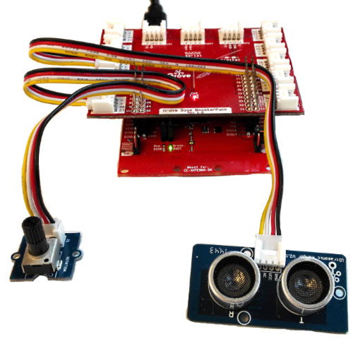
A diagram of the HW setup is shown below.

Prerequisites
==================================
Completed material
------------
* TI-RTOS Basics Lab 1
* SC Integrate Application
* For bonus task:
* BLE Custom Profile
* Proprietary RF EasyLink Network Processor example
Software for desktop development
----------------
* [Code Composer Studio 6.1.3+][CCS DL]
* [Sensor Controller Studio 1.3.0+][SCS DL]
* [TI-RTOS 2.20.01.08][TI-RTOS DL]
* For bonus tasks:
* [TI BLE SDK 2.2.1][TI BLE SDK]
* [Bluetooth Developer Studio][BDS]
* w/ [TI BLE SDK Plugin][BDS TI]
* BLE Scanner program/smart phone app
* [SmartRF Studio 7+][SMARTRF STUDIO]
[CCS DL]: https://www.ti.com/tool/ccstudio
[SCS DL]: https://www.ti.com/tool/SENSOR-CONTROLLER-STUDIO
[TI-RTOS DL]: https://www.ti.com/tool/ti-rtos-mcu
[TI BLE SDK]: https://www.ti.com/tool/ble-stack
[SMARTRF STUDIO]: https://www.ti.com/tool/smartrftm-studio
[BDS]: https://www.bluetooth.com/download-developer-studio
[BDS TI]: https://software-dl.ti.com/lprf/bds/ti-bds-plugin.html
Hardware
----------
* 1x [CC2650][CC2650 LP] or [CC1350][CC1350 LP] LaunchPad
* [Grove Starter Kit for LaunchPad][Grove Starter Kit], which supplies
* [Grove Base BoosterPack][Grove BoosterPack]
* [Grove Rotary Angle sensor][Grove Rotary Angle]
* [Grove Ultrasonic Ranger sensor][Grove Ultrasonic Ranger]
* 2x sensor connector cables
* Micro-USB cable for LaunchPad
* For bonus tasks:
* 1x [CC2650 LaunchPad][CC2650 LP] (Bonus Task 1)
* 2x [CC1350 LaunchPad][CC1350 LP] (Bonus Task 2)
[CC2650 LP]: https://www.ti.com/tool/launchxl-cc2650
[CC1350 LP]: https://www.ti.com/tool/launchxl-cc1350
[Grove BoosterPack]: https://www.seeedstudio.com/wiki/Grove_Base_BoosterPack
[Grove Starter Kit]: https://seeedstudio.com/depot/Grove-Starter-Kit-for-LaunchPad-p-2178.html
[Grove Rotary Angle]: https://www.seeedstudio.com/wiki/Grove_-_Rotary_Angle_Sensor
[Grove Ultrasonic Ranger]: https://www.seeedstudio.com/wiki/Grove_-_Ultrasonic_Ranger
Abbreviations / terminology
==================================
Abbreviation / terminology | Definition
---------------------------|-----------
CCS | Code Composer Studio
SC | Sensor Controller
SCS | Sensor Controller Studio
LP | LaunchPad
AUX RAM | Sensor Controller memory domain
RTC | Real-time Clock
RTOS | Real-time Operating System
TI-RTOS | RTOS for TI microcontrollers
BDS | Bluetooth Developer Studio
Task 0 – Import and build TI-RTOS project
==================================
First, before starting with SCS, we will import and build a fresh copy of the CCS project `ADC Ranger` used in this training. Then we will run it on the LaunchPad to verify that it's working. The project is a simple framework for the TI-RTOS application that allows us to simply modify an existing application task, easily show the different aspects of SC integration, and later show how to easily connect the SC to a larger project, such as Project Zero.
[[+b How to find your CCS workspace path
In CCS, go to `Project → Properties`, or press <kbd>Alt+Enter</kbd>. Click on `Build` section to the left. Navigate to the `Variables` tab. Click on `Show system variables` checkbox at the bottom. Scroll down until you find the `WORKSPACE_LOC` variable, and note the value. This is your CCS workspace path for your project.
+]]
Do the following:
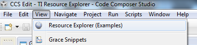
1. Open CCS and expand the Resource Explorer window
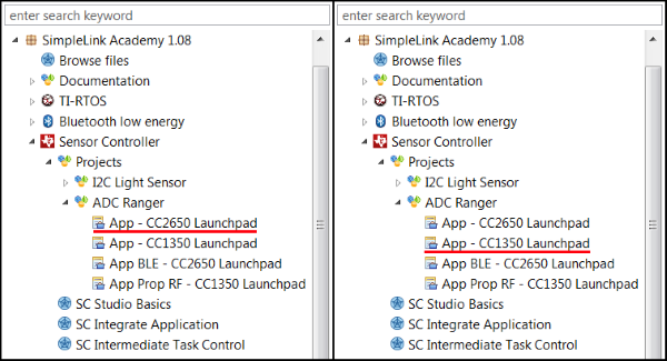
2. Locate project in correct folder and import.
* If you are using CC2650, use left navigation.
* If you are using CC1350, use right navigation.
3. If you have multiple LaunchPads connected, configure the debugger.
4. Build <kbd>Ctrl+B</kbd> and Debug <kbd>F11</kbd> the project. This should flash the program to the LP. Ignore the build warnings regarding unused functions. Press Resume or <kbd>F8</kbd> to start the application.
It is not easy to verify that the application is running correctly through CCS. However, the application is sending out log statements through UART, so we will open up a serial connection and see that it outputs correctly. This will also be useful for later application development. Expand section below to see how.
[[+b How to establish a serial connection
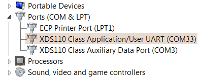
1. Go to [Windows Device Manager]{Start → Run → </br>`mmc devmgmt.msc`}, under `Ports (COM & LPT)` section, and see which COM the XDS1100 Class Application User UART is under. Note the COM number. If multiple LPs are connected, disconnect all other except the one to be used to find the correct COM line.
2. Open up your favorite [terminal program]{PuTTY, Tera Term, etc.}.
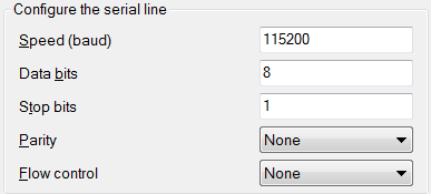
3. Insert correct settings and COM in terminal program. For this project the default UART settings are shown below.
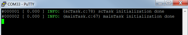
4. Press reset on the LP. If you see the output shown below the application has been successfully built and downloaded.
+]]
If you get problems establishing a serial connection, expand box below.
[[+y LaunchPad Serial Connection Problems Troubleshooting
Sometimes, when creating a serial connection with the LaunchPad, it can refuse to establish the connection. This can be a result of conflicting programs using said connection. This is resolved by
* closing all conflicting programs, including
* Code Composer Studio
* Sensor Controller Studio
* Already established serial connections
* clossing the terminal program.
* re-connecting the USB cable to the LP.
* starting the terminal program and create the serial connection.
+]]
[[g! Well done!
With the TI-RTOS application up and running, you are now ready to start creating the SC driver.
]]
--------------------
Task 1 – Setup SCS project
==================================
In this task we will setup and configure the SCS Project.
[[b! SCS Documentation and help
For documentation and help in SCS, `Help → Sensor Controller Studio Help` or press <kbd>F1</kbd> at any time.
]]
Create SCS project
----------------
Do the following:
1. Start SCS and open a new project, `File → New Project` or <kbd>Ctrl+N</kbd>.
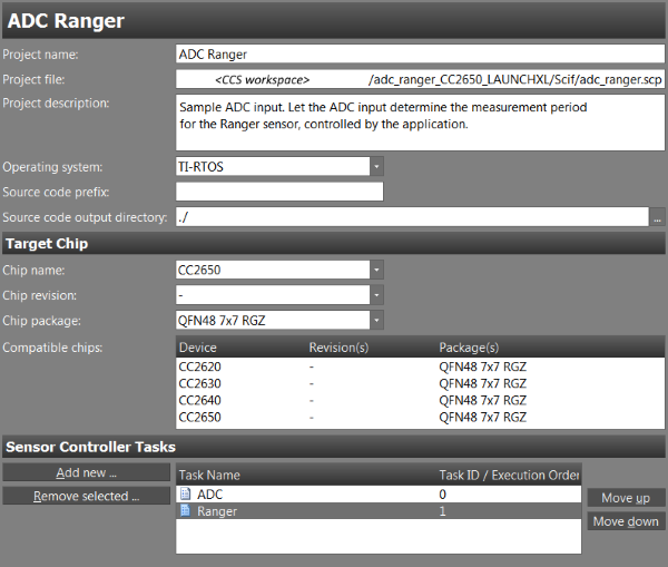
2. Set the `Project Name` to `ADC Ranger`, or something similar.
3. Set the `Operating system` to `TI-RTOS`.
4. Set `Source code output directory` to `./`.
5. Set `Chip name` to
* `CC2650` if using CC2650.
* `CC1350` if using CC1350.
6. Set `Chip package` to `QFN48 7x7 RGZ`.
7. Add two tasks by clicking `Add new`, name them `ADC` and `Ranger`.
8. Save the project, `File → Save Project` or <kbd>Ctrl+S</kbd>, to the `Scif/` folder in the CCS project base folder, located in your CCS workspace. See [Task 0](#task-0-ndash-import-and-build-ti-rtos-project) on how to find your CCS workspace path.
[[r! Correct project file save path
The path set in `Project file` **must** be the `Scif/` folder in your project base folder located in the CCS workspace. If not, then the output code generation will be wrong. As an alternative, the `Source code output directory` can be set to the absolute `Scif/` folder path in the CCS project.
]]
You should now have something akin to this.
[[g! Well done!
That was the easy part. Now comes the fun part!
]]
Task 2 – Implement ADC driver
==================================
First up is the ADC driver. The idea is to have an analog sensor which the user can manipulate and input a given value. Thus, we need an ADC driver to read these values from the sensor. It is supposed to be a simple, straightforward solution, which reads and samples the sensor on a periodic schedule and alerts the application.
{{y See SC Integrate Application for reference on how to create an ADC driver. }}
[[b! SCS project solution
Note that with the CCS project imported in [Task 0](#task-0-ndash-import-and-build-ti-rtos-project), a solution for the SCS project resides in the `Scif/` folder. This, as well as the [Solutions section](#solutions), can be used as reference for the finished project.
]]
Setup ADC driver
----------------
### ADC task properties
First we specify the resources the driver is going to use. Go to `Task Properties` for the ADC task, which can be accessed by clicking on the task name above the `Initialization Code`. Select the task resources in the list below.
* ** Analog Pins **
* Create one pin and name it `SENSOR_OUTPUT`.
* ** ADC **
* ** System CPU Alert **
* ** RTC-Based Execution Scheduling **
### ADC I/O mapping
After we have selected the task resources, we need to specify the pin for the sensor in the `I/O Mapping` window. In the `I/O Mapping` window, the pins are presented as the DIO pins on the LP. To find out which DIO the sensor is connected to, we have to trace to the connected pin on the Grove BoosterPack, then convert it to the corresponding DIO.
{{y If you have not already mounted the `Grove BoosterPack` on the `LaunchPad`, then do so now. Be sure the GND, 3V3 and 5V pins match. A red light should be shining on the `Grove BoosterPack` if done successfully. }}
Do the following:
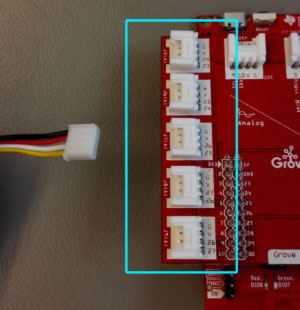
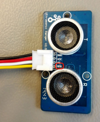
1. Connect the sensor to the `Grove BoosterPack` with a cable on one of the connectors shown in the picture below. You can choose whichever you want.
2. Carefully inspect under the analog sensor, in this case the rotary angle sensor, and see which wire is connected to the pin marked `SIG`. For the example picture below, we can see the yellow wire is connected to `SIG`.
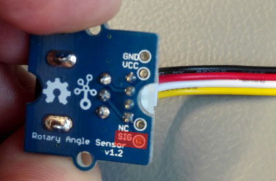
3. Trace the wire back to the `Grove BoosterPack` and note the connection number. In the example picture below, the yellow cable, which is the signal pin on the sensor, connects on `pin 25`. This number dictates which pin it is connected to on the `Grove BoosterPack`, and in turn, which DIO on the LP.
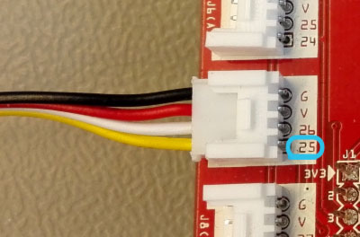
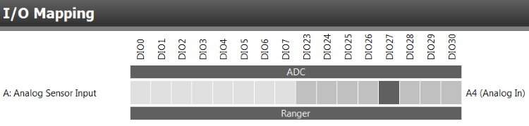
4. Convert the pin to the corresponding DIO on the LP. For convenience, a conversion table is provided below to easily convert pins from Grove BoosterPack to LP. For the example picture above, the resulting conversion for `pin 25` would be `DIO27`.
5. In the `I/O Mapping` window, select `CC2650 LaunchPad` or `CC1350 LaunchPad` for `Board Selection`, depending on which board you are using. When you have found the connected DIO pin, select it in the `I/O Mapping` window. For the example picture, the `DIO27` is selected.
[[b BoosterPack to LaunchPad PIN conversion table
* In the table below are the available pins for the SC.
* If you cannot find the pin number you have got, then it is not available for the SC and you have to change to a different connector.
BoosterPack | LaunchPad || BoosterPack | LaunchPad
------------|-----------||-------------|----------
2 | DIO23 || 25 | DIO27
3 | DIO3 || 26 | DIO28
4 | DIO2 || 27 | DIO29
6 | DIO24 || 28 | DIO30
9 | DIO4 || 29 | DIO0
10 | DIO5 || 30 | DIO1
23 | DIO25 || 39 | DIO6
24 | DIO26 || 40 | DIO7
]]
Implement ADC driver
----------------
Now, as the resources and I/O pins are specified, it is time to create the driver itself. What we want is the ADC task to sample an analog sensor, scheduled by the RTC. The pin we are sampling is the one specified above in the `I/O Mapping`. The value sampled should be stored in an output structure data member in the ADC task. After each sampling the task should generate an alert to the application.
[[y! Create data structure members
You need to create a data structure member in the output structure for the ADC driver to store the ADC value in. Name it `adcValue`, as that is what is used in the sample code of this training.
]]
A skeleton code for the ADC driver is presented below. To have some educational effect the complete code is not shown. Some parts of the code lines are censored. It is your job to fill in the **\*\*\*\*** parts. For help and hints on what to fill in, check out the `Available Procedures` in the bottom right corner in the code window. As the name implies, they show all available procedures for this given task. Double click on a procedure to open the relevant documentation. See picture below for reference.
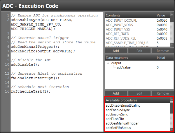
If you are stuck, or don't care at all, then a complete solution can be found at the [Solutions](#solutions) section.
[[b ADC driver: Skeleton code
```c
// Select the analog pin as ADC input
adc****(AUXIO_A_SENSOR_OUTPUT);
// Schedule first iteration
fwScheduleTask(1);
``` ADC driver: Initialization code
```c
// Enable ADC for synchronous operation with manual trigger
adc****(ADC_REF_FIXED, ADC_SAMPLE_TIME_2P7_US, ADC_TRIGGER_****);
// Generate manual trigger
// Read the ADC fifo and store the value
adc****();
adc****(output.adcValue);
// Disable ADC
adc****();
// Generate Alert to application
fwGenAlertInterrupt();
// Schedule next iteration
fwScheduleTask(1);
``` ADC driver: Execution code
]]
ADC driver testing
----------------
With the ADC driver implemented, the next logical thing is to test that it works. (If you still have an active debug session in CCS, SCS will not be able to connect to the target. In that case, press Terminate or <kbd>Ctrl+F2</kbd> in CCS to terminate the debug session before proceeding in SCS.)
Do the following:
1. Go to the `Task Testing` window, `View → Task Testing` or <kbd>Ctrl+T</kbd>.
2. Select your project and the `ADC` task.
3. Select `Use simplified workflow`. See picture below.
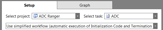
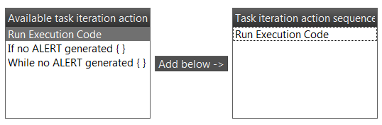
4. Add `Run Execution Code` to the `Task iteration action sequence`.
5. Click on `Connect` <kbd>F12</kbd>. You should now be in the graph tab.

6. Then, click `Run Task Iterations Continuously` <kbd>F5</kbd>.

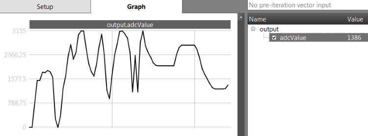
7. On the right side of the graph window you should find your output variable. Select it. A graph of the variable should appear. If there are no variables you might have forgotten to create it during coding.
8. Turn the knob on the analog sensor. You should see the graph change.
9. When you are content that the driver is working, click `Disconnect` <kbd>F11</kbd>.

[[g! Well done!
You have implemented and tested the ADC Driver. Next up is the Ranger Driver.
]]
-------------
Task 3 – Implement ranger driver
==================================
Now that the ADC driver is up and working, it is time to implement the Ranger driver. The idea with the Ranger driver is to have a ranger sensor measure the distance with a given measurement period, specified and controlled by the application.
Ultrasonic ranger sensor
----------------
The sensor we are using is the `Ultrasonic Ranger V2.0` by Grove. It is a non-contact distance measurement module. The sensor measures the distance by generating a sound and measuring how long the time of flight is for the sound wave. For more information about the sensor, see [references](#references).
The plan is to implement the driver in two steps:
1. Firstly by polling the signal and counting the number of iterations of polling, then converting to the actual value.
2. Secondly by timing how long the output signal is high with the [TDC]{Time to Digital Converter} library.
Ultrasonic ranger protocol
----------------
The sensor uses a custom protocol to transmit measurements. The protocol can be explained as such:
1. The SC pulls the pin high for 5 us to activate the Ranger sensor.
2. After the pin goes low the Ranger sensor waits a little under 0.5 ms.
3. Then the Ranger sensor responds by pulling the pin high and holds it as long as the generated sound travels in the air. In other words, the time of flight for the sound is the same as the time the pin is held high. In the picture below the ranger sensor holds the pin high for 11.15 ms.
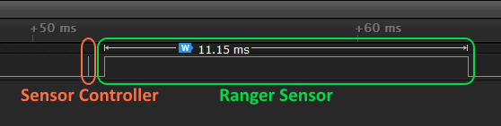
The Ranger sensor has a max range on its measurement, and will timeout after roughly 30.5 ms.
The conversion from sensor measurement to centimeters is very straightforward. Since the sensor measures the time of flight for a generated sound to travel back and forth a given distance, a simple equation for the distance can be derived:

<!-- $$ \text{distance} = \tfrac{1}{2} \cdot \text{speed of sound} \cdot \text{time of flight} $$ -->
With [speed of sound]{In dry air at 20°C} equal 343.2 metres per second, time of flight measured in microseconds, and distance represented in centimetres, we get the following equation:
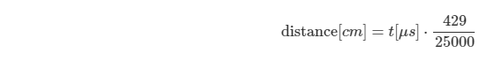
<!-- $$ \text{distance}[cm] = t [\mu s] \cdot \frac{429}{25000} $$ -->
This will be useful later when we implement this in the TI-RTOS application. For the graph above, where the ranger sensor holds the pin for 11.15 ms, the resulting distance with the derived equation is 191 cm.
Setup ranger driver
----------------
### Ranger task properties
First we need to specify the resources and the pin. Same as in [Task 2](#adc-task-properties), go to `Task Properties`. Select the task resources in the list below. We use an open-source pin
* **Digital Open-Source Pins **
* Create one pin and name it `RANGER`.
* **TDC **
* **Peripheral Sharing **
* **System CPU Alert **
* **RTC-Based Execution Scheduling **
* **Delay Insertion **
### Ranger I/O mapping
Follow the same procedure as the ADC driver in [Task 2](#adc-i-o-mapping) to configure the correct I/O Mapping. The signal pin on the Ranger sensor is shown on the picture below.
Polling method
--------------------
### Implement polling method
[[b! Available procedures during coding
All procedures needed for the implementation is found in the `Available Procedures` box in the bottom right corner in all code windows. As well, more information regarding the procedures can be found by double clicking them in the `Available Procedures` box, or in Help Viewer <kbd>F1</kbd>.
]]
`Termination Code` does not need to be implemented. A rough overview for the `Execution Code` can be summed up in 4 steps:
1. Drive the pin high for about 5ms.
2. Wait for the sensor to respond.
3. Measure / count how long the sensor drives the signal high.
4. Store the value, cleanup, and alert application.
What needs to be implemented is the `Initialization Code` and `Execution Code`, as well should the driver store the value in an output structure data member.
[[y! Create data structure members
You need to create a data structure member in the output structure for the Ranger driver to store the counter value in. Name it `counter`, as that is what is used in this training.
]]
Pseudo-code is presented below. The actual counter loop is already implemented, for reasons soon explained. If you are stuck, or don't care at all, then a complete solution can be found at the [Solutions](#solutions) section.
[[b Polling Method : Pseudo Code
```c
// Schedule first iteration
CODE GOES HERE
``` Polling Method : Initialization Code
```c
// Drive high for 5 us, steps:
// 1. Set pin high
// 2. Delay 5 us
// 3. Set pin low
CODE GOES HERE
// Enable the gpio input buffer
CODE GOES HERE
// Wait for answer
U16 pin;
do {
gpioGetInputValue(AUXIO_XS_RANGER; pin);
} while (pin == 0);
// Count how long the response is
U16 counter = 0;
do {
counter += 1;
gpioGetInputValue(AUXIO_XS_RANGER; pin);
} while (pin == 1);
// Store counter value
output.counter = counter;
// Disable the gpio input buffer, steps:
CODE GOES HERE
// Alert application
CODE GOES HERE
// Schedule next iteration
CODE GOES HERE
``` Polling Method: Execution Code
]]
### Test polling method
Now to test if the driver works. Go to the `Task Testing` window. Select the output counter variable and try to move your hand or other object above the ranger sensor. You should see the counter value change accordingly to your hand placement. See example picture below.

To convert the counter value to a distance unit, we need to know how long each counter translates to time units. Since the counter value represents the number of loop iterations, it's a matter of calculating how long time each loop iteration takes.
The loop present in the pseudo code takes [exactly 1 us]{Found by finding total number of clock cycles per loop iteration and divided by the CPU clock frequency} to execute one iteration. That means the counter value is effectively the time of flight in microseconds. This is why the counter loop was implemented for you.
Try to calculate the distance by using the equation derived in [Ultrasonic Ranger Protocol](#ultrasonic-ranger-protocol), and see if it seems reasonable.
[[r! Task testing timeout
If the task testing times out, it is because it entered an infinite loop. This is most likely because the pin in `I/O Mapping` window is not set correctly. Double check the pin, and see [Task 2](#adc-i-o-mapping) on how to choose the correct pin.
]]
Timer capture method
--------------------
### Implement timer capture method
[[b! Reusable code
The polling implementation is not needed anymore for this training. However, a lot of the code is the same in this implementation and can be reused.
]]
The polling method is an easy implementation of the driver, but not the most elegant nor flexible solution. Now we will try with the [TDC]{Time to Digital Converter} library in SCS. The TDC library allows us to measure time between a configurable start and stop trigger, which is perfect for this use case.
The TDC counter value from the library is represented as a 24-bit value. This means when we retrieve the counter value from the TDC library we have to store it as a high and low part in two unsigned 16-bit variables. We can then manually extend the two variables during testing.
[[y! Create data structure members
You need to create three data structure members in the output structure; two for the TDC counter value, and one for testing. Name them `tdcValueL`, `tdcValueH`, and [`tof`]{Time of flight}. Note that the `tof` data member is only used for testing purposes, and does not serve any purpose afterwards.
]]
Same as before, it is up to you to implement the code. As this might not be as intuitive as the polling method, a semi-complete code snippet is shown below. All TDC related code only needs to fill in the blanks, while the rest of the code can be reused from the polling method implementation.
[[b Timer capture method : Skeleton code
```c
// Set pin mode to output
CODE GOES HERE, SAME AS POLLING METHOD
// Schedule first iteration
CODE GOES HERE, SAME AS POLLING METHOD
``` Timer capture method : Initialization Code
```c
// Acquire shared peripherals, and enable TDC
fwAcquirePeripheral(PERIPHERAL_****);
tdc****();
// Select 2 x 24 MHz from RCOSC_HF as TDC counter clock source
tdc****(TDC_CNTSRC_48M_RCOSC);
// Enable the TDC with start trigger on AUXIO High and stop trigger on AUXIO Low
tdc****(TDC_STARTTRIG_AUXIO_**** + AUXIO_XS_RANGER, TDC_STOPTRIG_AUXIO_**** + AUXIO_XS_RANGER, 0);
// Drive high for 5 us
CODE GOES HERE, SAME AS POLLING METHOD
// Enable the gpio input buffer
CODE GOES HERE, SAME AS POLLING METHOD
// Arm TDC async, and wait 24 ms for answer
tdc****(TDC_START_ASYNC);
tdc****(24000);
// Get the TDC counter value
tdc****(output.tdcValueH, output.tdcValueL);
// Bitshift into one U16 variable
output.tof = (output.tdcValueH << 11) | (output.tdcValueL >> 5);
// Disable TDC, and release peripheral
tdc****();
fwReleasePeripheral(PERIPHERAL_****);
// Alert application
CODE GOES HERE, SAME AS POLLING METHOD
// Disable the gpio input buffer
CODE GOES HERE, SAME AS POLLING METHOD
// Schedule next iteration
CODE GOES HERE, SAME AS POLLING METHOD
``` Timer capture method : Execution Code
]]
### Test timer capture method
Finally let's test the Ranger driver one more time to see that it is working. Go to the `Task Testing` window. Select the `tof` data member in the output structure. Try moving your hand up and down over the sensor. You should see the variable steadily increase and decrease as you move your hand above the sensor. It should look something like the graph below.
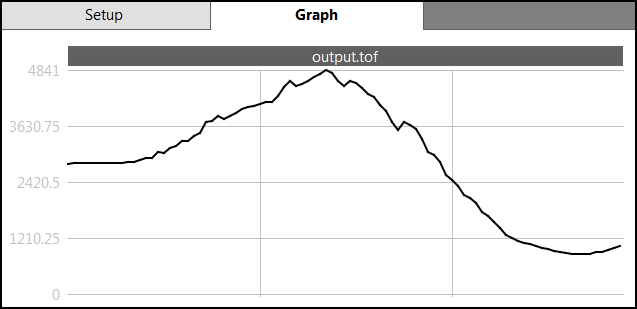
Note that the conversion from the `tof` variable to distance is not as straightforward as the polling method. See [Task 4](#implement-and-test-ranger-task) for a the actual conversion.
[[g! Well done!
You now have a working ADC and Ranger driver.
]]
-------------
Task 4 – Integrate SC into TI-RTOS application
==================================
Now that we have implemented the ADC and Ranger driver for the SC, the next thing to do is to integrate the SC into the TI-RTOS project we imported and built in [Task 0](#task-0-ndash-import-and-build-ti-rtos-project).
[[r! CCS project import
If you still haven't imported and built the project, go to [Task 0](#task-0-ndash-import-and-build-ti-rtos-project) and do that now.
]]
The main idea with the project is to have a periodic ADC task, where the ADC value sets the period for a period clock timer. Every periodic timeout starts a single exectuion of the Ranger task. This way we get two SC tasks with different execution periods, scheduled by either the RTC or by the TI-RTOS application.
An overview of the different signals, and the corresponding serivces and processes are shown in the figure below. The yellow blocks represent callbacks, where the blue blocks represent the source of the signal. The green blocks represent processing functions, run in task context in a main loop. Each callback signals the main loop with an event, which dispatches a corresponding function. The events are defined in the `application.h` file. Some of the processing functions interacts with the SC or the clock object.

A complete overview of the different functions to be implemented, and the flow of control between them, are shown in the figure below. All functions are found in the `scTask.c` file. The main loop block is already implemented in the `mainTask.c` file.

### Code documentation
Code documentation regarding the SC driver can be found at
* `scif_framework.h` file from code generation, see next section.
* SC interface documentation (doxygen), found on the start page.
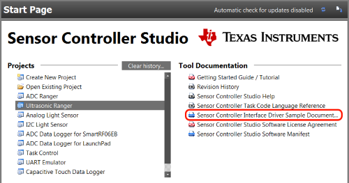
* The SC Integrate Application training.
### Code generation
First step is to generate code from the SCS project.
1. Go to the `Code Generator` window, `View → Code Generator` or <kbd>Ctrl+G</kbd>.
2. Select your project as `Current project`.
3. Either select `Output automatically` to auto generate code each time visiting the window, or click `Generate driver source code`.
4. Click `View output directory` and double check it is the `Scif/` folder of your TI-RTOS project.
5. Build the project and see that it compiles without errors.
{{r Make sure it is the correct output folder! }}
Initialization and setup of SC driver
----------------
If building the project was successful we can finally begin with the coding. In CCS, open the `scTask.c` file in the `Application/` folder. First we need to initialize and setup the SC driver. Go to the `SC_init()` function and copy paste the code snippet below.
```c
// Initialize the Sensor Controller
scifOsalInit();
scifOsalRegisterCtrlReadyCallback(SC_ctrlReadyHwiCb);
scifOsalRegisterTaskAlertCallback(SC_taskAlertHwiCb);
scifInit(&scifDriverSetup);
uint32_t rtcHz = 10; // 10Hz RTC
scifStartRtcTicksNow(0x00010000 / rtcHz);
// Configure SC Tasks here, if any
// Start Sensor Controller
scifStartTasksNbl(BV(SCIF_ADC_TASK_ID));
``` **scTask.c : SC_init()** - Initialization code
This initializes the SC driver, registers the two callbacks from SC, sets the RTC period, and starts the ADC task.
[[y! Scif task ID arguments
All `scif` functions handling task ID's, such as `scifStartTasksNbl()`, takes a bit vector as an argument. For your convenience, the macro `BV()` is already defined in `application.h` for this use.
]]
Setup interaction of SC
----------------
Next is to setup the interrupt callbacks from the SC. In `SC_init()` we registered two callback functions for each of the interrupt signals `Ctrl READY` and `Task ALERT`. Only the `Task ALERT` signal is of importance in this project. However, for completeness sake, we will handle both signals, but only process the `Task ALERT` signal.
At the top of the `scTask.c` file you will find the two functions `SC_ctrlReadyHwiCb()` and `SC_taskAlertHwiCb()`. The events are defined in the `application.h` file, where two events are already defined for these callbacks: `EVENT_SC_TASK_ALERT` and `EVENT_SC_CTRL_READY`. The HWI callbacks should signal the main task with the corresponding event.
So in short, for each callback function
1. Find the corresponding event in `application.h` file.
2. Signal main task by calling the `Main_signalEvents()` function with the corresponding event.
This should look something like the code snippet below.
```c
static void SC_ctrlReadyHwiCb(void)
{
// Signal the event to Main task
Main_signalEvents(EVENT_SC_CTRL_READY);
} // SC_ctrlReadyHwiCb
static void SC_taskAlertHwiCb(void)
{
// Signal the event to Main task
Main_signalEvents(EVENT_SC_TASK_ALERT);
} // SC_taskAlertHwiCb
``` **scTask.c : SC_ctrlReadyHwiCb() , SC_taskAlertHwiCb()** - SC callbacks
Then we need process the `Task ALERT` signal. Go to the `SC_processTaskAlert()` function. This is the function main task calls when the `EVENT_SC_TASK_ALERT` event is signaled. Copy and paste the code snippet below. This sets up and handles the alert handling from the SC.
```c
// Clear the ALERT interrupt source
scifClearAlertIntSource();
// Do SC Task processing here
// Acknowledge the ALERT event
scifAckAlertEvents();
``` **scTask.c : SC_processTaskAlert()** - SC task alert processing
Implement and test ADC task
----------------
Now we are ready for some action. First we implement the processing of the ADC task. Go to the `SC_processAdc()` function. Retrieve the ADC value from the `scifTaskData` structure and print out the variable. The code should look something like this:
```c
// Retrieve ADC value and print it
uint32_t adcValue = scifTaskData.adc.output.adcValue;
Log_info1("ADC value: %u", adcValue);
``` **scTask.c : SC_processAdc()** - SC ADC processing
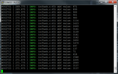
The `SC_processAdc()` should be called every time `Task ALERT` is signaled. Go to the `SC_processTaskAlert()` function, and call the `SC_processAdc()` after the alert interrupt source is cleared. Build and debug the project (make sure SCS is not connected to the target before you press the debug button in CCS), and observe the value printed out on the serial connection. You should see the red LED on the LP blink as well. Each toggle of the LED is an ADC task execution. Try using the sensor and observe the value changing. You should get see something like this.
Implement and test ranger task
----------------
Now for the Ranger task. The same will be done for the Ranger task as the ADC task.
1. Go to the `SC_processRanger()` function.
2. Retrieve both the low and high TDC value, build into a 32-bit value, and convert it to correct units. See below for help.
3. Print out the variable.
To convert from the TDC value to distance, a couple of steps are needed. First, the two TDC values need to be built into a 32-bit value. Then convert to microseconds by dividing by the TDC counter value by the clock counter frequency. The clock frequency used in TDC is 24MHz, but it counts both edges which makes it effectively 48MHz. Then to centimetres by using the equation derived in [Task 3](#ultrasonic-ranger-protocol). Use the code snippet below.
```c
// Retrieve and build TDC value
uint16_t tdcValueL = scifTaskData.ranger.output.tdcValueL;
uint16_t tdcValueH = scifTaskData.ranger.output.tdcValueH;
uint32_t tdcValue = (tdcValueH << 16) | tdcValueL;
// Convert from TDC value to time of flight[us]
uint32_t tof_us = tdcValue / 48;
// Convert from time of flight[us] to distance[cm]
uint32_t rangerDistance_cm = tof_us * 429 / 25000;
Log_info1("Ranger value: %ucm", rangerDistance_cm);
``` **scTask.c : SC_processRanger()** - SC ranger processing
Then we do the following:
1. Go to the `SC_init()` function.
2. Change `scifStartTasksNbl()` to start the Ranger Task instead of the ADC Task.
3. Go to the `SC_processTaskAlert()` function.
4. Modify the function to call `SC_processRanger()` instead of `SC_processAdc()`.
5. Build and debug the project, and observe the value printed out on the serial connection. Move your hand above the sensor and observe the value changing.
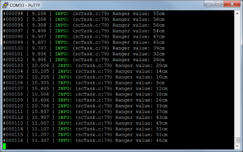
You should also see the green LED blink on the LP. Each toggle of the LED is a Ranger task execution.
[[g! Well done!
You have now integrated both the ADC and Ranger in the TI-RTOS application. The figure below shows what has been implemented by now. Shown in <font color="green">**green**</font> are <font color="green">**completed functions**</font>, while <font color="goldenrod">**yellow**</font> are <font color="goldenrod">**not final implementations**</font>. What remains to be done is to add a clock object, connect it to the `SC_rangerClockSwiFxn()`, implement the `SC_execRanger()` function, and setup the `SC_processAdc()` function to set the clock period.

]]
Task 5 – More complex SC task logic
==================================
By now we have implemented the initialization of SC, setup of communication between SC and application, and the processing of each SC task. That is good and all, but we want it to do more than just read and print sensor values. In this task we will extend the handling of several SC tasks, and some interaction between the ADC task and Ranger task.
Handle SC alert events
----------------
In the previous task, only one SC task at the time was running. Now, we want both the ADC and Ranger Task to run at the same time. This requires some extended logic in the `SC_processTaskAlert()` function.
First of all, we need to start both tasks at initialization. Go to `SC_init()` and change `scifStartTasksNbl()` to start both the ADC and Ranger Task. This can be done by taking the bitwise OR operator between the two bit vectors, see example below.
```c
// Start Sensor Controller
scifStartTasksNbl(BV(ID_1) | BV(ID_2));
``` **scTask.c : SC_init()** - Modified SC initialization
Then, we need to modify `SC_processTaskAlert()` to distinguish between different task alerts. This is done by using the SC function `scifGetAlertEvents()`. It returns a bit vector indicating which SC Tasks that have generated an alert event. We can then check upon the bit vector and handle it however we like. This gives us the potential to create more complex task logic.
For now, we will check for each task and call the corresponding process function. Replace the `SC_processRanger()` call with the code snippet below.
```c
// Get the alert events
uint32_t bvAlertEvents = scifGetAlertEvents();
// Check which task called and do process
if (bvAlertEvents & BV(SCIF_RANGER_TASK_ID)) {
SC_processRanger();
}
if (bvAlertEvents & BV(SCIF_ADC_TASK_ID)) {
SC_processAdc();
}
``` **scTask.c : SC_processTaskAlert()** - SC alert handling
Build and debug the project. You should observe that both the ADC and Ranger values are printed on the serial connection. Try adjusting the ADC sensor or move your hand above the Ranger. The values should change.
Add clock object
----------------
Now it's starting to get interesting. We are adding a clock object in the TI-RTOS application to generate period callbacks. The clock period will be set by the ADC value. From the callbacks we then invoke the Ranger Task execution manually.
[[y! Change in Scif initialization
Remove `BV(SCIF_RANGER_TASK_ID)` from `scifStartTasksNbl()` in `SC_init()`. It should look like the code snippet below.
```c
// Start Sensor Controller
scifStartTasksNbl(BV(SCIF_ADC_TASK_ID));
``` **scTask.c : SC_init()** - Modified SC task start
]]
First add `#include <ti/sysbios/knl/Clock.h>` at the top of the `scTask.c` file. Then create a global variable of type `Clock_Struct`, and call it `g_rangerClock`. Go to `SC_init()`. Before the SC is initialized, initialize the Ranger clock with a period of 0 ms. The callback function to be used is `SC_rangerClockSwiFxn()`, and should already be defined.
An example on how you can initialize the clock:
```c
// clockParams is only used during init and can be on the stack.
Clock_Params clockParams;
// Insert default params
Clock_Params_init(&clockParams);
// Set period to 0 ms
clockParams.period = 0;
// Initialize the global clock object.
Clock_construct(&g_rangerClock, // global clock struct
SC_rangerClockSwiFxn, // callback from clock
0, // Initial delay before first timeout
&clockParams); // clock parameters
``` **scTask.c : SC_init()** - Clock object initialization
From the code above we defined in the `Clock_construct()` the callback function to be `SC_rangerClockSwiFxn()`. This tells the clock object to call `SC_rangerClockSwiFxn()` every time it times out.
Connect clock to ranger task
----------------
So what should `SC_rangerClockSwiFxn()` do? The function is periodic, and the idea is to let the ADC sensor value set the period of the clock object. Therefore, the function should invoke an execution of the Ranger Task. An important distinction is that it should not start the Ranger Task as we have done before in `SC_init()`. This would start the task scheduled by the RTC, which is not what we want. We want to execute the Ranger Task once.
To execute the task once, a couple of precautions need to be taken. First we need to make sure the task is not already active. Since we are explicitly executing the Ranger task periodically we need to check it is not already active. This is done by calling the `scifGetActiveTaskIds()`, which returns a bit vector of active tasks, and checking against it.
Next we need to reset the data structures of the associated task. This is because executed tasks will have modified data structures, which marks them as "dirty", and we cannot execute a "dirty" task. Resetting the data structures removes the "dirty" condition.
Then we can call the actual invocation of the execution with the function `scifExecuteTasksOnceNbl()`. Go to the function `SC_execRanger()` and add the following code snippet:
```c
// Check Ranger Task is not already active
uint16_t bvActive = scifGetActiveTaskIds();
if (bvActive & BV(SCIF_RANGER_TASK_ID)) {
return;
}
// Execute Task once
scifResetTaskStructs(BV(SCIF_RANGER_TASK_ID), 0);
scifExecuteTasksOnceNbl(BV(SCIF_RANGER_TASK_ID));
``` **scTask.c : SC_execRanger()** - Ranger task execution
The main task should now call the function `SC_execRanger()` whenever the event `EVENT_SC_EXEC_RANGER` is signaled. So in the function `SC_rangerClockSwiFxn()`, signal main task with said event. See code snippet below.
```c
// Signal main task
Main_signalEvents(EVENT_SC_EXEC_RANGER);
``` **scTask.c : SC_rangerClockSwiFxn()** - Clock process signalling
Connect ADC value to clock period
----------------
All that remains now is to connect the ADC value to the Ranger clock object period.
Go to `SC_processAdc()`. There are multiple ways to convert the ADC value to a given period. For this task we will define an upper and a lower limit for a value range, then convert the ADC value to the value range with a linear function. The ADC value is in the value range [<GND, VCC>]{Units [mV]}, which for the LP is [<0, 3300>]{Units [mV]}. This makes the transformation easy.
We also need to combat dispatch jitter, as the ADC task can be executed on a faster period than the Ranger task clock, or simply by timing. This means that the ADC task can restart the clock faster than the clock can timeout. Simply create a global variable `g_lastTick` with the type `uint32_t`. Then, in `SC_rangerClockSwiFxn()`, add the following line before signaling main task:
```c
static void SC_rangerSwiFxn(UArg a0)
{
g_lastTick = Clock_getTicks();
// Signal main task
Main_signalEvents(EVENT_SC_EXEC_RANGER);
} // SC_rangerSwiFxn
``` **scTask.c : SC_rangerClockSwiFxn()** - Modified SWI process
And finally, go to `SC_processAdc()` and paste the code snippet below. The macros `TICK_TO_MS` and `MS_TO_TICK` converts between clock ticks and milliseconds, and are defined in the `application.h` file.
```c
// Retrieve ADC value and saturate at 3000
uint16_t adcValue = scifTaskData.adc.output.adcValue;
adcValue = (adcValue < 3000) ? adcValue : 3000;
// Calculate new Ranger clock period in the range <MINVAL, MAXVAL>[ms]
#define MAXVAL 1000
#define MINVAL 333
uint32_t newPeriod_ms = (MAXVAL - MINVAL) * adcValue / 3000 + MINVAL;
// Calculate ranger clock timeout, to prevent dispatch jitter
uint32_t currRangerExec_ms = TICK_TO_MS(Clock_getTicks() - g_lastTick);
uint32_t newTimeout_ms = (currRangerExec_ms < newPeriod_ms)
? newPeriod_ms - currRangerExec_ms
: 0;
// Re-configure the Ranger clock with new period and timeout
Clock_Handle hRangerClock = Clock_handle(&g_rangerClock);
Clock_stop(hRangerClock);
Clock_setPeriod(hRangerClock, MS_TO_TICK(newPeriod_ms));
Clock_setTimeout(hRangerClock, MS_TO_TICK(newTimeout_ms));
Clock_start(hRangerClock);
``` **scTask.c : SC_processAdc()** - New ADC processing
Build and debug, and see the wonderful results!
[[g! Well done!
You have now completed the training! In the figure below shows the complete overview of the application, and what has been implemented.

Want more? Check out the bonus tasks below.
]]
------------------
Bonus Task 1 – BLE integration
==================================
In this bonus task we are integrating the SC application into a BLE device. Since the actual integration could be a training in itself, an almost finished project has been made for you.
The project can be found in `Resource Explorer` under the name `App BLE - CC2650 LaunchPad`. It is a modified version of `Project Zero` with a finished integration of the SC application. What is left up for you to do is to create the BLE services for the ADC and Ranger task. When importing the `App BLE - CC2650 LaunchPad` project, its stack project called `project_zero_stack_cc2650` should also be imported. Build and load this project into the LaunchPad before starting on the `App BLE - CC2650 LaunchPad` project.
[[b! Copy over Scif files
You need to copy over the 6 `Scif` files over to the `Scif/` folder in this project.
]]
The SC application is/should be pretty much the same as the resulting application in task 5. The only changes are the `Main_signalEvents()` are replaced with the messaging function `user_enqueueRawAppMsg()`, which serve the same purpose as they signal the main task, and in `SC_processAdc()` and `SC_processRanger()` the corresponding BLE service characteristics are updated with the `user_enqueueCharDataMsg()` function.
[[y! Hardware requirement
This bonus task requires a CC2650 LaunchPad.
]]
BLE service creation
-------------
To create the BLE services, we are going to use the developer tool `Bluetooth Developer Studios` with the TI BLE SDK Plugin. See the workshop about [Bluetooth Developer Studio](../ble_01_bds/ble_01_bds.html) for how to use that tool.
[[y! Hardcoded naming convention
The naming convention of the BDS project will have an impact on the generated code. Since the CCS project is hardcoded for a given set of BLE services, it is important you follow the naming convention below.
]]
Do the following:
1. Open up Bluetooth Developer Studio.
2. Create a new project, and name it `ADC Ranger`. Choose whichever namespace you like. Press `OK`.
3. Add a new service.
1. Click `Custom Service` in the top right corner.
2. Name the service `ADC Service`.
3. Click `Save`.
4. Add a characteristic by clicking `(+)` below the service name.
5. Name the characteristic `Value`.
6. Set characteristic properties `Read` and `Notify` to `Mandatory`.
7. At the bottom left of the characteristic window, click `Add Fields`, and then `Add`.
8. Name the field `Value`, and set the format to be `UINT8_ARRAY`.
9. Click `Done` in the fields window, and click `Save` in the characteristic window.
4. Add a new service, by following the same procedure as the `ADC` service.
1. Name the service `Ranger Service`.
2. Add a characteristic and name it `Distance`.
3. Set the same characteristic properties.
3. Add a field to the characteristic and name it `Distance`.
4. Set the format for the field to be `UINT8_ARRAY`.
5. Generate code for the BLE services.
1. Press <kbd>Ctrl+G</kbd> to enter `Generate Code` window.
2. Choose the TI plugin.
3. Click `Generate`. This takes a few seconds.
4. Click the checkbox `Open output location when finished` **before** clicking `Finish`. Alternatively navigate to the BDS workspace.
6. Copy and paste the files into the CCS project.
1. In the opened window, go into the `AdcRanger_TI` folder, and copy the `adc_service.c/h` and `ranger_service.c/h` files.
2. Paste the files in the `PROFILES/` folder in the CCS project, located in the CCS workspace.
7. In CCS, build and debug the project.
The project should now build and load the program into the LaunchPad. (Please make sure that you have loaded the `project_zero_stack_cc2650` project before you load the `App BLE - CC2650 LaunchPad` project.) If you get build errors regarding `adc_service` or `ranger_service`, double check in BDS that correct names are set.
BLE device testing
-----------
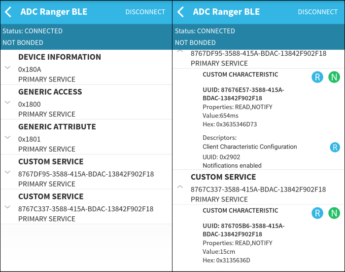
Start your favorite BLE app on your smartphone. Connect to the BLE device called `ADC Ranger BLE`. 5 services should be presented. The two bottom custom services are the ADC and Ranger services, in that order. See picture below on how it should look. Note the value displayed.
Try to read the characteristics on both services. Do this multiple times while turning the angle sensor and moving your hand above the ranger sensor. Now enable notification on either characteristics. Try again using the sensors and see the value change.
[[g! Well done!
Your SC application is successfully integrated into a BLE device!
]]
Bonus Task 2 – Proprietary RF integration
==================================
In this bonus task we are integrating the SC application with Proprietary RF. The intention is to show how you could use Proprietary RF to transmit data from the SC application.
The project can be found in `Resource Explorer` under the name `App Prop RF - CC1350 LaunchPad`. It should be nearly identical to the resulting project from task 5 with some slight modifications, namely some added initialization in `SC_init()` and an extra function `SC_txPacket()` which is self-explanatory.
[[b! Copy over Scif files
You need to copy over the 6 `Scif` files over to the `Scif/` folder in this project.
]]
The `EasyLink` API is used for Proprietary RF. See Prop RF EasyLink Network Processor API for more info regarding Proprietary RF and EasyLink.
[[y! Hardware requirement
This bonus task requires two CC1350 LaunchPad; one for Tx and one for Rx.
]]
Tx packet configuration
--------------
What is left up for you to do is to complete the `SC_txPacket()` function. What is missing is to add the Ranger value to the Tx packet payload. See code snippet below on what needs to be completed.
```c
// Create packet with incrementing sequence number
static uint16_t seqNumber = 0;
txPacket.payload[0] = /* TODO High byte of seqNumber */;
txPacket.payload[1] = /* TODO Low byte of seqNumber */;
/* TODO Increment seqNumber */
// Format Ranger value to ASCII with units and add to payload
char pLine[20];
itoaAppendStr(pLine, rangerValue, "cm");
size_t lineLen = strlen(pLine);
/* TODO Copy pLine into payload index 2 */
memcpy(/* payload address */, /* pLine address */, /* length of pLine */);
```
Tx packet testing
-------------
First, only let the one CC13XX with the Grove BoosterPack be connected to the PC. Then debug the CCS project and load the program. After that is done, connect the second CC13XX. Start SmartRF Studio, and connect to the second device. Both devices should have the red debug LED on the top left corner shining.
In SmartRF Studio, configure Packet Rx with frequency `869.7MHz`, Tx Power `12dBm`, and Address check `aa-bb`, as this is used in the EasyLink library. Set packet count to infinite, viewing format to text, and press start.
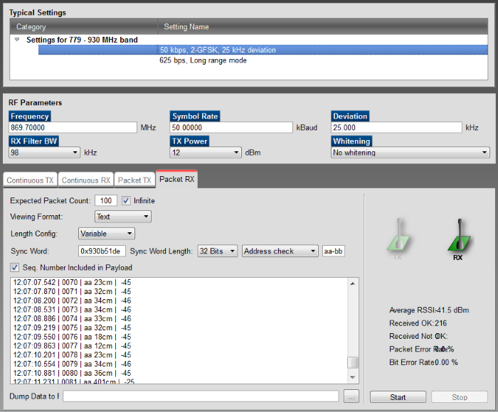
Resume execution in CCS if this is not already done. You should now see the packets arrive in SmartRF Studio. The Ranger value is shown after the address `aa` in the payload. Try moving your hand above the Ranger sensor, and adjust the measurement period with the Rotary Angle sensor.
[[g! Well done!
You have now finished the entire training! Want to learn more? Check out the other trainings.
]]
References
==================================
* **TI-RTOS Kernel and Driver Documentation** – Available in the `doc` folder of the TI-RTOS installation root folder. It is also available online: [TI-RTOS 2.20 Drivers API][TI-RTOS Drivers API].
* **Technical Reference Manual** – Available on the [TI Website][Technical Reference Manual]
* **Grove Rotary Angle Sensor Wiki** – Available on [seeed Wiki][Rotary Angle Wiki].
* **Grove Ultrasonic Ranger Wiki** – Available on [seeed Wiki][Ultrasonic Ranger Wiki].
<!-- Definition of inline references -->
[Technical Reference Manual]: https://www.ti.com/lit/swcu117
[TI-RTOS Drivers API]: https://software-dl.ti.com/dsps/dsps_public_sw/sdo_sb/targetcontent/tirtos/2_20_01_08/exports/tirtos_full_2_20_01_08/products/tidrivers_cc13xx_cc26xx_2_20_01_10/docs/doxygen/html/index.html
[Ultrasonic Ranger Wiki]: https://www.seeedstudio.com/wiki/Grove_-_Ultrasonic_Ranger
[Rotary Angle Wiki]: https://www.seeedstudio.com/wiki/Grove_-_Rotary_Angle_Sensor
Solutions
==================================
You dirty cheat. Sure you tried hard enough? Be kind to yourself and only use this as a guideline, and not as a cookbook recipe.
----------
[[+b ADC Driver
### ADC Driver Solution - Initialization Code
```c
// Select the GPIO analog pin as ADC input
adcSelectGpioInput(AUXIO_A_SENSOR_OUTPUT);
// Schedule first iteration
fwScheduleTask(1);
```
### ADC Driver Solution - Execution Code
```c
// Enable ADC for synchronous operation
adcEnableSync(ADC_REF_FIXED, ADC_SAMPLE_TIME_2P7_US, ADC_TRIGGER_MANUAL);
// Generate manual trigger
// Read the sensor and store the value
adcGenManualTrigger();
adcReadFifo(output.adcValue);
// Disable the ADC
adcDisable();
// Generate Alert to application
fwGenAlertInterrupt();
// Schedule next iteration
fwScheduleTask(1);
```
+]]
[[+b Ranger Driver: Polling Method
### Polling Method: Initialization Code Solution
```c
// Schedule first iteration
fwScheduleTask(1);
```
### Polling Method: Execution Code Solution
```c
// Drive high for 5 us
gpioSetOutput(AUXIO_XS_RANGER);
fwDelayUs(5, FW_DELAY_RANGE_10_US);
gpioClearOutput(AUXIO_XS_RANGER);
// Enable the gpio input buffer
gpioEnableInputBuf(AUXIO_XS_RANGER);
// Wait for answer
U16 pin;
do {
gpioGetInputValue(AUXIO_XS_RANGER; pin);
} while (pin == 0);
// Count how long the answer is
U16 counter = 0;
do {
counter += 1;
gpioGetInputValue(AUXIO_XS_RANGER; pin);
} while (pin == 1);
// Store counter value in an output structure data member
output.counter = counter;
// Disable the gpio input buffer
gpioDisableInputBuf(AUXIO_XS_RANGER);
// Alert application
fwGenAlertInterrupt();
// Schedule next iteration
fwScheduleTask(1);
```
+]]
[[+b Ranger Driver: Timer capture method
### Timer capture method: Initialization Code Solution
```c
// Schedule first iteration
fwScheduleTask(1);
```
### Timer capture method: Execution Code Solution
```c
// Acquire shared peripherals, and enable TDC
fwAcquirePeripheral(PERIPHERAL_TDC);
tdcEnable();
// Select 2 x 24 MHz from RCOSC_HF as TDC counter clock source
tdcSetCntSource(TDC_CNTSRC_48M_RCOSC);
// Enable the TDC with start trigger on AUXIO High and stop trigger on AUXIO Low
tdcSetTriggers(TDC_STARTTRIG_AUXIO_HIGH_BASE + AUXIO_XS_RANGER, TDC_STOPTRIG_AUXIO_LOW_BASE + AUXIO_XS_RANGER, 0);
// Drive high for 5 us
gpioSetOutput(AUXIO_XS_RANGER);
fwDelayUs(5, FW_DELAY_RANGE_10_US);
gpioClearOutput(AUXIO_XS_RANGER);
// Enable the gpio input buffer
gpioEnableInputBuf(AUXIO_XS_RANGER);
// Ready TDC and wait 24 ms for answer
tdcArm(TDC_START_ASYNC);
tdcWaitUs(24000);
// Get TDC value
tdcGetValue(output.tdcValueH, output.tdcValueL);
output.tof = (output.tdcValueH << 11) | (output.tdcValueL >> 5);
// Disable TDC, and release the peripheral
tdcDisable();
fwReleasePeripheral(PERIPHERAL_TDC);
// Alert application
fwGenAlertInterrupt();
// Disable the gpio input buffer
gpioDisableInputBuf(AUXIO_XS_RANGER);
// Schedule execution next tick
fwScheduleTask(1);
```
+]]