Introduction
==================================
This workshop shows how to use the *Bluetooth®* SIG's Bluetooth Developer Studio (`BDS`), which is a graphical user interface for designing Bluetooth profiles and generating buildable source code which implements the services and characteristics that have been designed.
This workshop will walk you through how to implement the services in Project Zero using BDS and discuss the features and limitations of the TI plugin.
[[b! What's Project Zero
For details on Project Zero, please see the `Project Zero getting started instructions` link below, and also the [video on training.ti.com](https://training.ti.com/simplelink-academy-develop-your-bluetooth-low-energy-project) that walks you through these instructions.
**Note:** The instructions and the video use the cloud IDE at **dev.ti.com**, where **BLE SDK 2.1** is currently the latest available release. This workshop uses the **BLE SDK 2.2**. The code output from the Bluetooth Developer Studio plugin will *not* work with BLE SDK 2.1.
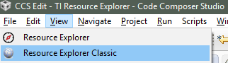
For this workshop, please import `Project Zero` from the `SimpleLink Academy` package in `Resource Explorer (Classic)` when asked to do this later.
]]
Prerequisites
==================================
### Completed material
* [Project Zero getting started instructions](https://dev.ti.com/tirex/#/Device/CC2650?link=CC26xx%20Bluetooth%20Smart%2FDevelopment%20Tools%2FCC2650-LAUNCHXL%2FDocuments%2FCC2650-LAUNCHXL%20Project%20Zero) on dev.ti.com
* [Bluetooth Low Energy Fundamentals workshop](../ble_01_basic/ble_01_basic.html) – Referenced later in workshop, and explains using Project Zero locally, with BLE SDK 2.2.
* [Making a Custom Profile workshop](../ble_01_custom_profile/ble_01_custom_profile.html) – Optional, but explains what is going on behind the scenes in this workshop.
### Software for desktop development
* [CCS 6.1.3+](https://processors.wiki.ti.com/index.php/Download_CCS) installed with support for CC13xx/CC26xx devices
* [TI BLE SDK 2.2.1](https://www.ti.com/ble-stack)
* [TI BLE Device Monitor](https://www.ti.com/lit/zip/swrc258)
* [Bluetooth Developer Studio] – This has been tested with version 1.1
* [BDS Plugins] – Find and download the [TI plugin](https://software-dl.ti.com/lprf/bds/ti-bds-plugin.html) here. Tested with version 1.07.
[[r! Compiler Support
The BLE-Stack v 2.2.1 SDK release has been built and tested with TI ARM Compiler `v5.2.6`. Compatibly with other TI ARM Compiler versions in CCS has not been tested and use of other compiler versions may result in undefined behavior. Refer to Section 2.6.3.2 of the [BLE Software Developer's Guide (SWRU393)](https://www.ti.com/lit/pdf/swru393) for the procedure to install TI ARM Compiler `v5.2.6`.
]]
### Hardware alternatives
* CC2650 Launchpad
* CC2650ST SensorTag + DEVPACK-DEBUG
* SmartRF06 Evaluation board + CC2650EM-7ID
### Recommended reading
* Chapter 1 and 2 of the BLE Software Developer's Guide
* Found at [https://www.ti.com/lit/pdf/swru393](https://www.ti.com/lit/pdf/swru393) or in the SDK install dir under `docs`.
* [TI BDS Plugin download and getting started](https://software-dl.ti.com/lprf/bds/ti-bds-plugin.html)
Getting started
==================================
Install
--------
First, download and install the software listed under <a href="#prerequisites">Prerequisistes</a>.
* The `BLE SDK` will also install a compatible version of `TI-RTOS`.
* Install `Bluetooth Developer Studio`
* Open the zip-file containing the [TI BDS Plugin](https://software-dl.ti.com/lprf/bds/ti-bds-plugin.html), and copy/extract the folder called `Texas Instruments -- Embedded Profiles` into `C:\Program Files (x86)\Bluetooth SIG\Bluetooth Developer Studio\Plugins\`
First look
-----------
Bluetooth Developer Studio lets you easily design your services, and if you have the `PTS Dongle` hardware peripheral sold by Bluetooth SIG you can also use this tool to test your custom profile as it's running on physical hardware.
In the screenshot below you can see the default view in BDS, where you design the profile.
| 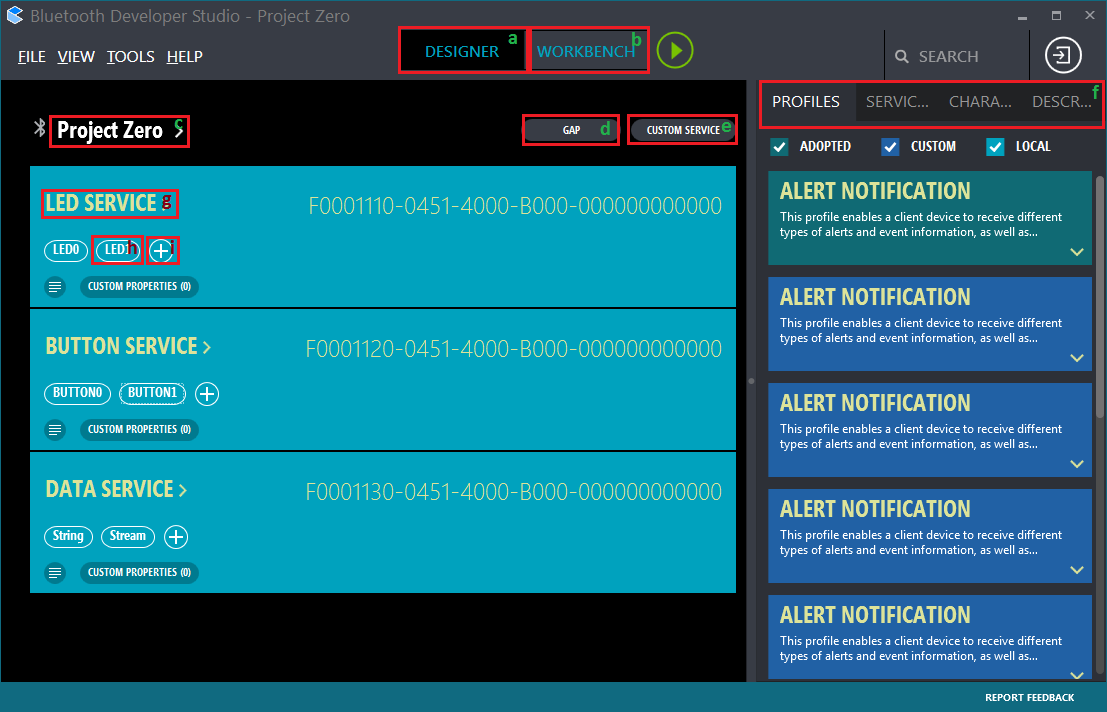 |
| ---------------------------------------------|
| **Project Zero** services implemented with Bluetooth Developer Studio. Click to open the screenshot enlarged.
The elements in the screenshot above are as follows:
**a** – Designer view, the current view.
<br/>**b** – Workbench view, for testing the services
<br/>**c** – Settings for the profile. Name, base UUID, namespace. Generated code gets base UUID from here.
<br/>**d** – GAP settings, device name, advertising data.
<br/>**e** – Add a new custom service to the active project
<br/>**f** – Adopted and otherwise available Bluetooth profiles, services and characteristics
<br/>**g** – Settings for the Service. UUID.
<br/>**h** – Access the properties for a particular characteristic in the service
<br/>**i** – Add a new characteristic to the service
Most of these, including the `Tools` menu and some sub-views will be used in the following walkthrough.
[[b! Video resources
When you have just launched `BDS` or if you click *View→Dashboard*, there are some videos in the right hand pane that explain some of the basics of using the tool.
]]
New Project
=======================
The goal of this workshop is to exactly replicate the functionality in `Project Zero`, and the first step in that process is to make a new project.
In dashboard view, click on `NEW` or click `File > New`
Create project
--------------
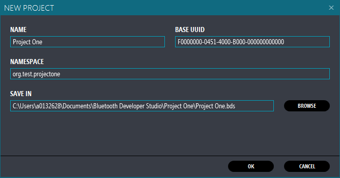
* Call the project whatever you want, but since your project obviously will be superior to Project Zero, this is called `Project One` here.
* Use the base UUID `F0000000-0451-4000-B000-000000000000` so Device Manager, BTool and the Sensortag app will recognize the services.
* This the 128-bit namespace used by TIs examples. You can make your own by inserting random hex characters instead or by following some [UUIDscheme](https://en.wikipedia.org/wiki/Universally_unique_identifier).
* For reference, the Bluetooth SIG adopted profiles are in the `00000000-0000-1000-8000-00805F9B34FB` "namespace".
* Insert some namespace. This doesn't really matter, but it's perhaps nice to be consistent.
* Click OK
Customize profile description
---------------------------
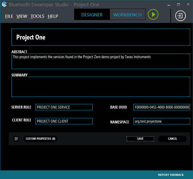
* Change `New Profile` into someting more appealing. Like `Project One`. Do this by clicking on it.
* This will be the name of the output folder for the generated code.
* If you want, add abstract, summary and change the description of the server and client roles.
* Click on `Save`. Now you're ready to roll.
Configure GAP settings
-----------------------
**NOTE:** You must click `SAVE` or `CANCEL` on the profile settings view before the `GAP` button, `(d)` seen in the picture above, appears. `SAVE` is recommended at this stage.
If GAP settings don't exist, the plugin will choose some defaults. But we want to change this here.
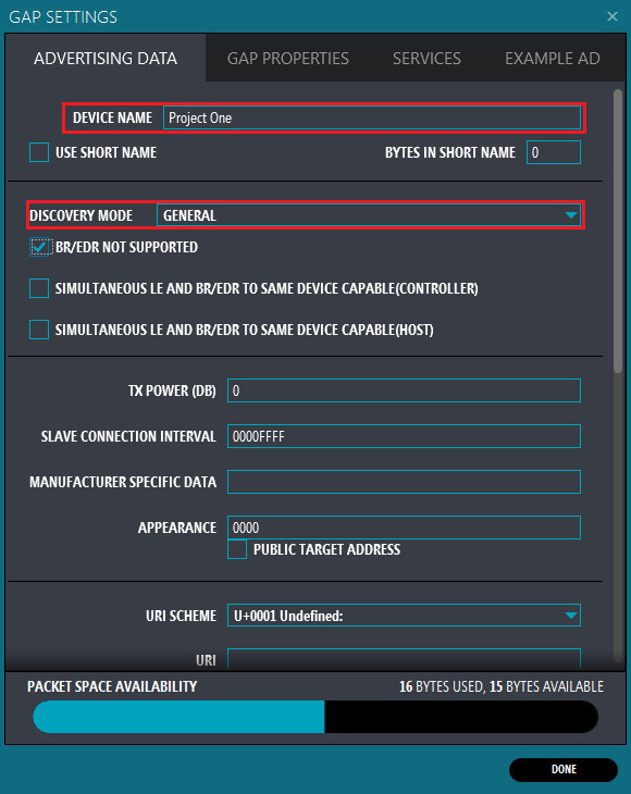
* Set `Device Name` to `Project One`
* This is used in the `Device Name` characteristic of the GAP Service, and in the advertisement data
* Set advertising mode to `General` so that it doesn't stop advertising.
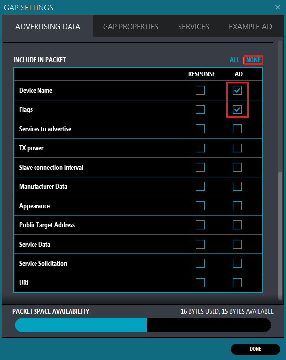
This is further down in the same view. Here you can choose what to include in the `Advertising Data (AD)` and in the `Scan Response`
* Select NONE of the fields
* Then add `Device Name` and `Flags`
* In practice, it doesn't work to exclude Flags because the plugin will ensure this is added to `Advertising Data` regardless, as it is a required field in the spec.
[[b! Supported settings
Currently, the only settings supported by the code generator plugin are:
* Device Name + whether to use short version in adv/scan data
* Discovery mode
* Adv/Scan data content
* Flags (always included in AdvData)
* Device Name (LocalName)
* Advertise device has services (16-bit and 128-bit)
* TX Power
]]
[[d! Generated content
In the section <a href="#generate-some-code">Generate Some Code</a> it is explained how to use the code generator plugin. If follow these instructions and open the file `project_zero_bds.c`, you will find the content below. Note that the GUI will not execute the plugin until at least one service is defined.
```c
// GAP - SCAN RSP data (max size = 31 bytes)
static uint8_t scanRspData[] =
{
// No scan response data provided.
0x00 // Placeholder to keep the compiler happy.
};
// GAP - Advertisement data (max size = 31 bytes, though this is
// best kept short to conserve power while advertisting)
static uint8_t advertData[] =
{
// Flags; this sets the device to use limited discoverable
// mode (advertises for 30 seconds at a time) or general
// discoverable mode (advertises indefinitely), depending
// on the DEFAULT_DISCOVERY_MODE define.
0x02, // length of this data
GAP_ADTYPE_FLAGS,
DEFAULT_DISCOVERABLE_MODE | GAP_ADTYPE_FLAGS_BREDR_NOT_SUPPORTED,
// complete name
12,
GAP_ADTYPE_LOCAL_NAME_COMPLETE,
'P', 'r', 'o', 'j', 'e', 'c', 't', ' ', 'O', 'n', 'e',
};
// GAP GATT Attributes
static uint8_t attDeviceName[GAP_DEVICE_NAME_LEN] = "Project One";
``` **project_zero_bds.c** Result of GAP settings
]]
Creating a Custom Service
===============
To create a service, we must
* Add a new service
* Configure the service
* Add a characteristic
* Configure the characteristic
* Add fields to this characteristic
Add a New Service
------------------
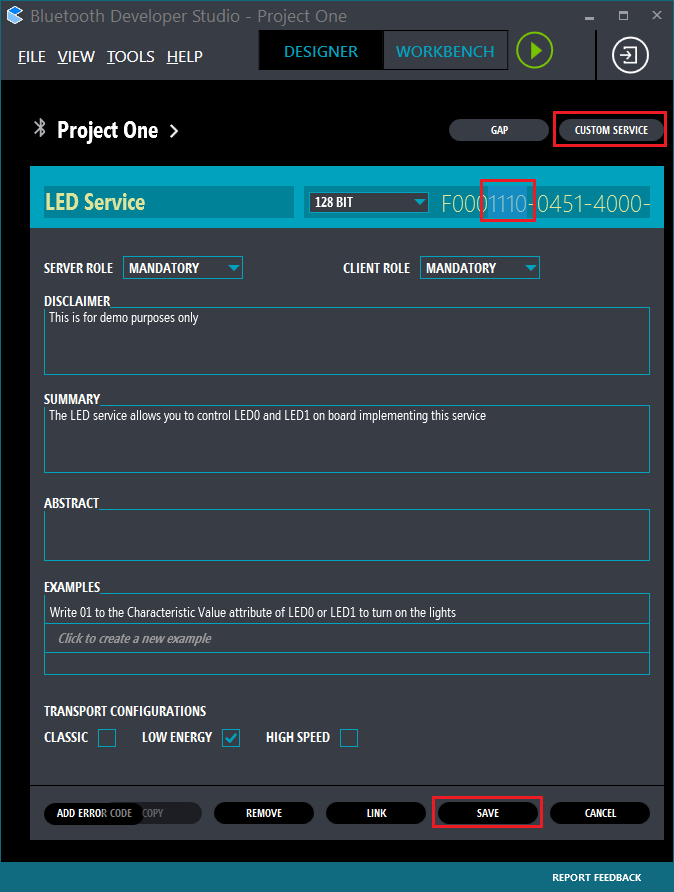
The `LED Service` is a service that contains two `Characteristics`, LED0 and LED1. The UUID of the service is the TI base UUID + `0x1110` in the 16-bit part of the UUID.
* After saving, click on the `CUSTOM SERVICE` button to add a new service
* Change the name of the service to `LED Service`
* This will determine the name of the generated service files
* Change the 16-bit part of the base UUID (marked in red) to `1110`
* This is the `LED Service UUID` used by Project Zero.
* Fill in the other fields as desired and hit save.
* Hit save
Note that the code generator plugin ignores the `TRANSPORT CONFIGURATIONS`, as the BLE SDK only supports `LOW ENERGY`.
[[d! Generated content
When code is generated for a service, a service implementation and header file is made, and some code is added to the application to initialize and use the service.
```c
// Service UUID
#define LED_SERVICE_SERV_UUID 0x1110
#define LED_SERVICE_SERV_UUID_BASE128(uuid) 0x00, 0x00, // etc
//...
// Callback when a characteristic value has changed
typedef void (*LedServiceChange_t)( uint16_t connHandle, uint16_t svcUuid, uint8_t paramID, uint8_t *pValue, uint16_t len );
typedef struct
{
LedServiceChange_t pfnChangeCb; // Called when characteristic value changes
LedServiceChange_t pfnCfgChangeCb; // Called when characteristic CCCD changes
} LedServiceCBs_t;
//...
extern bStatus_t LedService_AddService( uint8_t rspTaskId );
extern bStatus_t LedService_RegisterAppCBs( LedServiceCBs_t *appCallbacks );
extern bStatus_t LedService_SetParameter( uint8_t param, uint16_t len, void *value );
extern bStatus_t LedService_GetParameter( uint8_t param, uint16_t *len, void *value );
``` **led_service.h** API Calls and UUID define
```c
// Bluetooth Developer Studio services
#include "led_service.h"
// ...
static void ProjectZero_init(void)
{
// ...
// Add services to GATT server and give ID of this task for Indication acks.
LedService_AddService( selfEntity );
// Register callbacks with the generated services that
// can generate events (writes received) to the application
LedService_RegisterAppCBs( &user_LED_ServiceCBs );
// ...
``` **project_zero_bds.c** Use of the API calls
]]
Add a Characteristic
--------------------
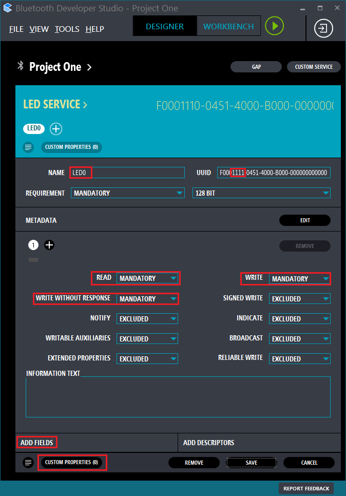
`LED0` is a characteristic whose `Characteristic Value` attribute can be written to with a `1-byte control word` (`0x00` or `0x01`) to control the state of `LED0` on the target board.
The characteristic must therefore be `Writable`. It could also be made readable.
* Click on the `(+)` button in LED Service
* Fill out as in the screenshot above
[[b! Access properties
The code generator has concept of checking the various options that can be set for `Read`, `Write`, etc. Therefore, any setting other than `EXCLUDE` will make the code generator include code for and enable the access properties.
Also note that only the properties `READ`, `WRITE`, `WRITE WITHOUT RESPONSE`, `NOTIFY` and `INDICATE` are used by the code generator. `SIGNED WRITE` and `RELIABLE WRITE` are normally always available if `WRITE` is enabled.
]]
### Adding a Field to the Characteristic
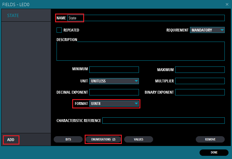
We want a 1-byte control word, so we should add one field and specify the format to `UINT8`.
* Click `ADD` and call the field something like `state`.
* Change the `Format` to `UINT8`
* Optionally add enumerations for the values. These only appear as comments for now.
[[b! What's a field then?
If you imagine each characteristic's value as an array of bytes (because that's what it is), then this array could be imagined as being mapped to a struct, with fields.
**Note:** The sum of the size of the fields you add will determine the length/size of the array that stores the characteristic value in the generated code.
```c
union {
uint8_t as_array[3];
struct __attribute((packed))__ { // gcc style
uint8_t field_state;
uint16_t field_somethingElse;
} as_struct;
} my_char;
my_char.as_struct.field_state = 31;
my_char.as_array[0] == 31; // --> true
``` Pseudocode for how to imagine the fields for a characteristic.
]]
#### Enumerations
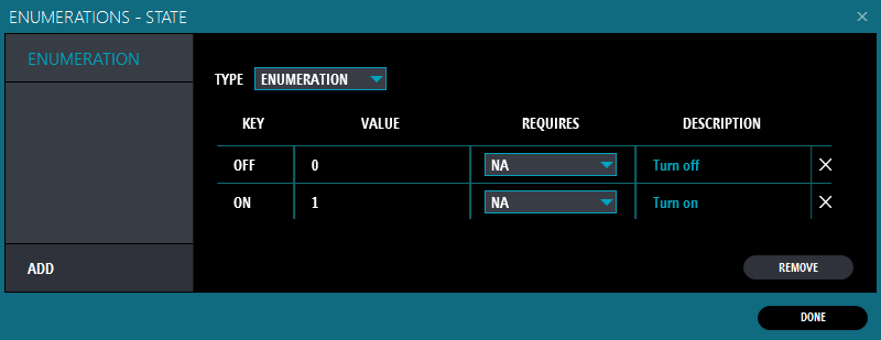
* Choose type `ENUMERATION` and start typing.
* To add a new line, hit <kbd>Enter</kbd> when the cursor is in one of the data fields.
* When finished, click `DONE` to get to the `Fields` view, then `DONE` again to get to the `LED0` Characteristic view.
As mentioned above, this is currently for documentation purposes as far as the code generator plugin is concerned.
```c
// Fields in characteristic "LED0"
// Field "State" format: uint8, bits: 8 <-- appears for fields
// Enumerations for State <-- extra output for enums
// 0 -- OFF
// 1 -- ON
``` Example enum output in `led_service.h`
### Custom Properties
`BDS` allows you to specify custom properties for a lot of things, like your profile, services and characteristics. For the TI plugin, some custom properties have special meaning when added to `Characteristics`.
See the [TI BDS Plugin README](https://software-dl.ti.com/lprf/bds/ti-bds-plugin.html) for detailed descriptions.
| Property | Description
| --------- | -----------
| OUTPIN | Sets the `PIN` specified by the property's value to the state specified in the first byte of the received data on the characteristic
| INPIN | Registers and interrupt for the `PIN` specified and updated the characteristic value when the pin state changes
| INBUTTON | Like `INPIN` but also adds debounce logic before updating
The value of the property should be something that maps to an `IOID` number usable by the PIN driver, for example `1`, `IOID_1` or `Board_LED0`.
The added properties will cause code to be added to the generated application code output file called `project_zero_bds.c`. This application already includes definitions from `Board.h`, so these can be used as values.
There are no checks to see if your value made sense, and it is perfectly allowable, if a bit meaningless, to specify `Board_BUTTON0` as an output pin, or to specify an `OUTPIN` on a characteristic that cannot be written to.
#### Set custom property for LED0
Since we want to control a LED, we obviously want to set the PIN state to whatever we recieve over the air.
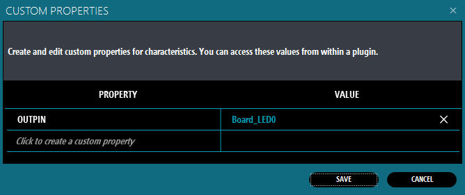
* First, get back to the `LED0` setting page by exiting the `Fields` view.
* Click on the `CUSTOM PROPERTIES` button
* Add the property `OUTPIN` with the value `Board_LED0`
* Click save
* Click done to get back to the `LED0` view.
* Click save in the `LED0` characteristic view to save your changes for this characteristic.
[[d! Generated content
For each characteristic added, UUID defines are added to the service header file, and initialization of the characteristic is added to the application
```c
// LED0 Characteristic defines
#define LS_LED0_ID 0
#define LS_LED0_UUID 0x1111
#define LS_LED0_UUID_BASE128(uuid) 0x00, 0x00, // etc
#define LS_LED0_LEN 1
#define LS_LED0_LEN_MIN 1
``` **led_service.h** Added defines per Characteristic
You will notice in the above that `_LEN` and `_LEN_MIN` are both set to 1. This is because we added a `uint8` field to the characteristic.
Some code is also added to the application
```c
// ...
uint8_t someVal[20] = {0};
// Initalization of characteristics in LED_Service that can provide data
// to a peer device over the air.
LedService_SetParameter(LS_LED0_ID, LS_LED0_LEN, &someVal);
// ...
static void user_processApplicationMessage(app_msg_t *pMsg)
{
// ...
switch (pMsg->type)
{
case APP_MSG_SERVICE_WRITE: /* Message about received value write */
/* Call different handler per service */
switch(pCharData->svcUUID) {
case LED_SERVICE_SERV_UUID:
user_LedService_ValueChangeHandler(pCharData);
// ...
// See below for the change handler function
``` **project_zero_bds.c** Initialization and handling of writes
In addition, if you add custom properties, extra code for handling PINs is added.
```c
// ...
static PIN_Handle userPinHandle;
static PIN_State userPinState;
PIN_Config userPinTable[] = {
Board_LED0 | PIN_GPIO_OUTPUT_EN | PIN_GPIO_LOW | PIN_PUSHPULL | PIN_DRVSTR_MAX,
PIN_TERMINATE
};
// ...
// Open user PINs
userPinHandle = PIN_open(&userPinState, userPinTable);
if(!userPinHandle) {
Log_error0("Error initializing board pins");
Task_exit();
}
// ...
void user_LedService_ValueChangeHandler(char_data_t *pCharData)
{
// ...
switch (pCharData->paramID)
{
case LS_LED0_ID:
// ...
PIN_setOutputValue(userPinHandle, Board_LED0, pCharData->data[0]);
``` `project_zero_bds.c` Added code when OUTPIN is given as a property
]]
Generate Some Code
==================================
Now that you have made a profile with a service with a characteristic with a field and a custom property, you have something that works and actually does something.
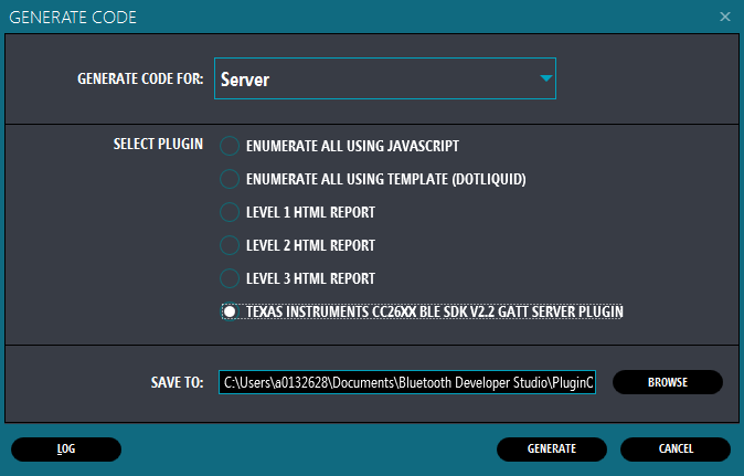
* First save the changes you have made to the characteristic
* In the `TOOLS` menu, choose `GENERATE CODE`
* Select the Texas Instruments plugin
* Click `Generate`
## Log output
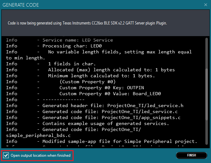
When you generate code, the plugin's log output appears in a window. The same log is also stored as `log.txt` in the output directory.
Notice that each service and characteristic along with the guessed at (based on the format of the fields) length is displayed.
* Select `Open output directory` and click `Finish` when you're done reading the log.
* Find the output in the opened folder under `ProjectOne_TI`.
## File and variable names
You will notice that some automagic occurs when generating the code. For example, the code and header files for a service will use a lower case version of the service name, with underscores: `service_name.c`.
| Thing | Input | Example | Description
| -- | ----- | -- |
| File names | Service Name | `service_name.c/h` | Lower case and underscore
| API Calls | Service Name | `ServiceName_SetParameter(..)` | CamelCase and contracted
| Service UUID | Service Name | `SERVICE_NAME_SERV_UUID` | Upper case and underscore
| Char UUID | Service Name, Char Name | `SN_CHAR_NAME_UUID` | Upper case, abbreviation of initials in "Service Name"
| Char param ID | Service Name, Char Name | `SN_CHAR_NAME_ID` | Upper case, abbreviation of initials in "Service Name"
## Plugin and templates
If you are very interested, feel free to look into `Plugin.js`, `service.c|h` and `project_zero_bds.c` in the folder you extracted to the `Plugin` directory of BDS. The template files use `Liquid.js` syntax to generate the output, based on JavaScript objects put together by `Plugin.js`.
[[+b Some template and output examples. Click to expand.
As an example, here's how the hardware interrupt for pins is generated, based on `Plugin.js`'s parsing of the custom properties.
```c
static void pinHwiFxn(PIN_Handle handle, PIN_Id pinId)
{
// Whether to disable Hwi for 'pinId' after handling the interrupt
int disableHwi = 0;
// Get current value of the button pin after the clock timeout
uint8_t pinVal = PIN_getInputValue(pinId);
Log_info1("Pin interrupt: IOID_%d", (IArg)pinId);
switch (pinId)
{
{% for pin in pins.list -%}
{% if pin.input or pin.button -%}
case {{ pin.define }}:
{% if pin.button -%}
// Start debounce clock for this pin
Clock_start(Clock_handle(&{{pin.nameCap}}DebounceClock));
disableHwi = 1; // Disable interrupt until debounce is complete
{% else -%}
// Send message to application that it should update the value of the characteristic from Task context.
user_enqueueCharDataMsg(APP_MSG_UPDATE_CHARVAL, 0xFFFF,
{{ pin.service.name | upcase }}_SERV_UUID,
{{ service.nameAbbr | upcase }}_{{ char.name | upcase }}_ID,
&pinVal, 1);
{% endif -%}
break;
{% endif -%}
{% endfor -%}
}
if (disableHwi)
{
// Disable interrupt on that pin for now. Re-enabled after debounce.
PIN_setConfig(handle, PIN_BM_IRQ, pinId | PIN_IRQ_DIS);
}
}
{% endif -%}
``` **project_zero_bds.c (template) :: pinHwiFxn()** A list of switch case statements is built up from the list of pins.
It's all really just `{% for thing in things %}` and `{{thing.value}}`, sprinkled with some `if` and `else`s. Here's what the output looks like when `Board_BUTTON0` is given as value to an `INBUTTON` entry.
```c
switch (pinId)
{
case Board_BUTTON0:
// Start debounce clock for this pin
Clock_start(Clock_handle(&button0DebounceClock));
disableHwi = 1; // Disable interrupt until debounce is complete
break;
}
``` **pinHwiFxn()** Generated part if BUTTON0 is added. Calls `buttonDebounceSwiFxn` on timeout.
As another example, here's how the service template for `YourService_GetParameter` looks:
```c
bStatus_t {{ service.nameCap }}_GetParameter( uint8_t param, uint16_t *len, void *value )
{
bStatus_t ret = SUCCESS;
switch ( param )
{
{% for char in service.charsNeedWrite -%}
case {{ service.nameAbbr | upcase }}_{{ char.name | upcase }}_ID:
*len = MIN(*len, {{ service.nameAbbr}}_{{ char.nameCap }}ValLen);
memcpy(value, {{ service.nameAbbr}}_{{ char.nameCap }}Val, *len);
Log_info2("GetParameter : %s returning %d bytes", (IArg)"{{ char.nameCap }}", (IArg)*len);
break;
{% endfor -%}
default:
Log_error1("GetParameter: Parameter #%d not valid.", (IArg)param);
ret = INVALIDPARAMETER;
break;
}
return ret;
}
``` **service.c :: xxGetParameter()** Names API after the service name and fills in boilerplate.
Again for reference, this is the output:
```c
bStatus_t LedService_GetParameter( uint8_t param, uint16_t *len, void *value )
{
bStatus_t ret = SUCCESS;
switch ( param )
{
case LS_LED0_ID:
*len = MIN(*len, ls_LED0ValLen);
memcpy(value, ls_LED0Val, *len);
Log_info2("GetParameter : %s returning %d bytes", (IArg)"LED0", (IArg)*len);
break;
default:
Log_error1("GetParameter: Parameter #%d not valid.", (IArg)param);
ret = INVALIDPARAMETER;
break;
}
return ret;
}
``` **led_service.c :: LedService_GetParameter()** `LS_LED0_ID` is how you address LED0 via this API.
+]]
Compile the Code
==================================
So far so good! Now we will replace the default user application and services in the `Project Zero` project with what we just made.
[[b! Use Resource Explorer 'Classic' for SimpleLink Academy material
If you are using Code Composer Studio 6.2.x it is necessary to use the 'Classic' version of Resource Explorer to view the training material and import the projects.
]]
* Import, build and program `Project Zero` for your board as described in the workshop [BLE Fundamentals Task 1](../ble_01_basic/ble_01_basic.html#task-1-ndash-run-projectzero-project) to see that everything works as expected
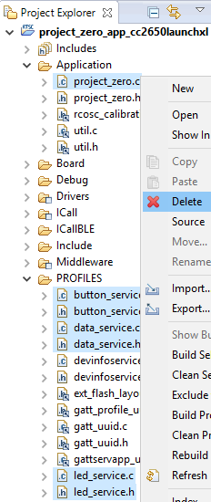
* Now, delete `project_zero.c` – **not `.h`** and the custom services for LED, Button and Data, both the `.c` and `.h` files.
* Next copy in the files you just generated by dragging them to the `Application` folder in the IDE.
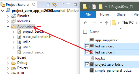
You are free to choose `Copy` or `Link` in the dialog that pops up next, but note that if you choose `Link` then any changes you do will be overwritten next time you use `Generate Code` in the BDS GUI.
* Re-build the project, download it to the device and run it.
Explore the Service over BLE
=================================
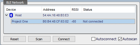
Now we want to see that it works as advertised. Refer to [BLE Fundamentals Task 2](../ble_01_basic/ble_01_basic.html#task-2-connect-and-navigate-exposed-services) for how to connect to your target board. The below screenshots are from `TI BLE Device Monitor`.
When you do a scan for BLE devices using some tool, you should see a device advertising with the name `Project One`, or whatever you chose in the GAP setting in BDS.
When you connect and discover the services, you will see that the LED Service is present and has one Characteristic.
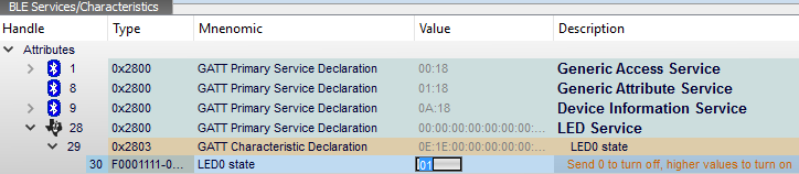
If you write `01` to this characteristics you should see the LED light up on the board.
[[b! Mnemonics and descriptions
When Device Monitor and BTool are able to provide useful descriptions here, this is because the meta-data for the Project Zero services is included in an XML file included with the application. Since we used the same UUIDs as the LED Service and LED0 Characteristic, they just assumes that it is the same thing. `UUID` means `Universally Unique Identifier` after all.
]]
Add Everything Else
===========================
The basic steps are outlined above, so the following is somewhat abbreviated. Please refer to the previous sections if anything is unclear.
When new services and characteristics are added, and new code is generated, the new or updated files must be added to the `Project Zero` CCS project and the project must be re-built.
LED Service
------------
We are almost finished here, just one characteristic remaining
### Add LED1
* Do the same as when adding `LED0`, except
* Use the 16-bit UUID part `1112`
* Name it `LED1` instead where applicable
[[b! Copy characteristic
You can also click on the `COPY` button while editing `LED0` to duplicate it, but note that the `CUSTOM PROPERTIES` will not be copied, and neither will the `UUID` (for obvious reasons). The fields and access properties are copied.
]]
Button Service
---------------
The basic steps here are the same for adding the service and characteristics. The difference is summarized below
| Service Name | Service UUID
| ----------- | -------
| Button Service | `TI BASE` + `1120`
| Characteristic | UUID | Properties | Field(s) | Custom Property
| ----------- | --- | ----- | ---- | ------
| BUTTON0 | `1121` | Read, Notify | `uint8` | INBUTTON=Board_BUTTON0
| BUTTON1 | `1122` | Read, Notify | `uint8` | INBUTTON=Board_BUTTON1
[[y! Client Change Configuration Descriptor
The TI code generator plugin will automatically add a `CCCD` type descriptor to any characteristic that has either `Indicate` or `Notify` enabled. You can add this descriptor manually in the GUI as well for completeness, but descriptors are currently ignored by the generator.
]]
Data Service
--------------
| Service Name | Service UUID
| ----------- | -------
| Data Service | `1130`
| Characteristic | UUID | Properties | Field(s)
| ----------- | --- | ----- | ----
| String | `1131` | Read, Write | `uint8_array`
| Stream | `1132` | WriteWoRsp, Notify | `uint8_array`
In order to be functionally identical to Project Zero, the length of the `String` characteristic must be manually updated to be `40 bytes` long.
This is because the length-guessing that occurs during code generation assumes that any characteristic that contains variable length fields can be between 1 and 20 characters long. The reason 20 bytes is default max is that for devices that do not support increased MTU sizes, 20 bytes is the maximum length usable in a notification.
To be exact, the assumed minimum length is the sum of the fixed fields or 1 byte of no fixed fields are found.
```c
// String Characteristic defines
#define DS_STRING_ID 0
#define DS_STRING_UUID 0x1131
#define DS_STRING_UUID_BASE128(uuid) 0x00, 0x00, 0x00, // etc
#define DS_STRING_LEN 20
#define DS_STRING_LEN_MIN 1
``` **data_service.h** Modify the `DS_STRING_LEN` to 40.
In addition, the `String` characteristic must be initialized with an interesting string in the applications initialization section.
```c
uint8_t myStr[] = "This is a pretty long string, isn't it?";
DataService_SetParameter(DS_STRING_ID, sizeof myStr, myStr);
``` **project_zero_bds.c :: ProjectZero_init()** Add to the service and characteristic intialization section.
Using the Workbench and PTS dongle
==================================
This section will just briefly show how to use the `Workbench` view and the Protocol Viewer with the PTS dongle
[[b! Documentation
Documentation on how to use the Workbench view, the virtual client scripting and the PTS dongle can be found by clicing on `HELP > HELP` on the menu.
[Direct link to Workbench help on docs.bluetooth.com](https://docs.bluetooth.com/developerstudio/workbench/index.html)
]]
[[r! Installing PTS dongle driver
The documentation for how to install the driver can be hard to find, but this is what you can do if it doesn't work:
* Plug in the PTS dongle
* Open Device Manager, and find "Generic Bluetooth Radio" under "Bluetooth". If it isn't working then it should be expanded and have an icon overlay.
* Choose Update Driver Software... and browse your computer
* Find `C:\Program Files (x86)\Bluetooth SIG\Bluetooth Developer Studio\PTS Driver\[win64 or win32]`
* It seems Windows chooses the wrong driver sometimes, if you do not manually select `win32` or `win64`
* Now it should show up under USB Controllers as CSR BlueCore Bluetooth
]]
Starting the Protocol Viewer
----------------------------
From the `TOOLS` menu, select `PROTOCOL VIEWER`. If it is not installed, follow the instructions to install it.
Once it's started press the red record button, or select Live → Start capture...
Connecting
------------
This assumes that you have already generated, build and downloaded the `Project One` profile to your target board.
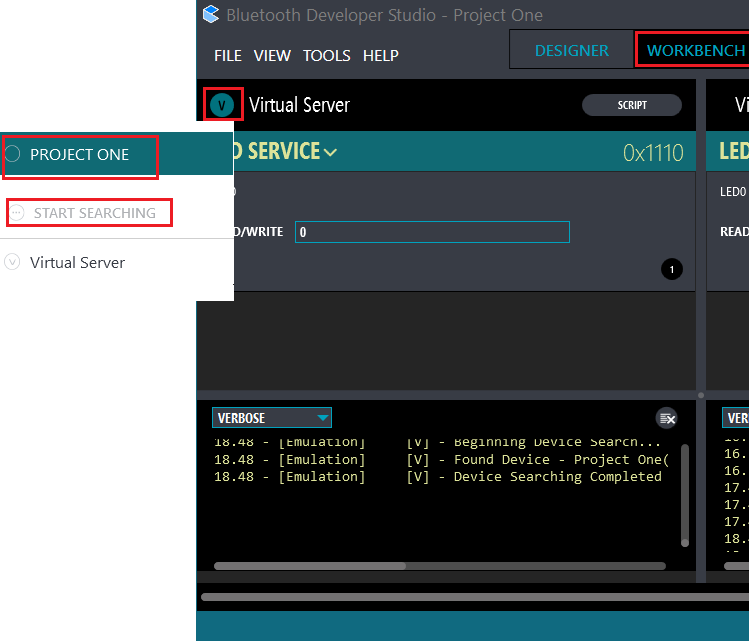
Go to the `WORKBENCH` view, click on the `V` and select `START SEARCHING`, then choose to connect to `PROJECT ONE`.
The log should show you something like this:
```text
19.11 - [Emulation] [V] - Attempting to connect to device - Project One ...
19.11 - [Emulation] [V] - Attempting to connect to device - B0B448CF6302 ...
19.11 - [Emulation] [V] - Response From Connect - SUCCESS
19.11 - [Emulation] [V] - Connected Successfully
19.11 - [Emulation] [V] - Interrogating Device
19.11 - [Emulation] [V] - Discovering Services
19.11 - [Emulation] [V] - Found 4 services
19.11 - [Emulation] [V] - Discovering Characteristics For Service - 1800
19.11 - [Emulation] [V] - Found 3 Characteristics For Service - 1800
19.11 - [Emulation] [V] - Discovering Characteristics For Service - 1801
19.11 - [Emulation] [V] - No Characteristics Found For Service - 1801
19.11 - [Emulation] [V] - Discovering Characteristics For Service - 180a
19.11 - [Emulation] [V] - Found 9 Characteristics For Service - 180a
19.11 - [Emulation] [V] - Discovering Characteristics For Service - f000111004514000b000000000000000
19.11 - [Emulation] [V] - Found 1 Characteristics For Service - f000111004514000b000000000000000
19.11 - [Emulation] [V] - About to read from Physical Device with handle - 30
19.11 - [Emulation] [V] - Completed read from Physical Device with handle - 30 - (SUCCESS)(1)
19.11 - [Emulation] [V] - f0001111-0451-4000-b000-000000000000 - Format of type is uint8
```
This indicates that Bluetooth Developer Studio was able to connect and find the LED Service and the LED0 characteristic.
It also finds the other default services that are added to Project Zero by default.
In the Profile Viewer you should see something like this, which is the last part of the Service and Characteristic Discovery, and then a couple of Read requests and Write commands to the LED0 service.
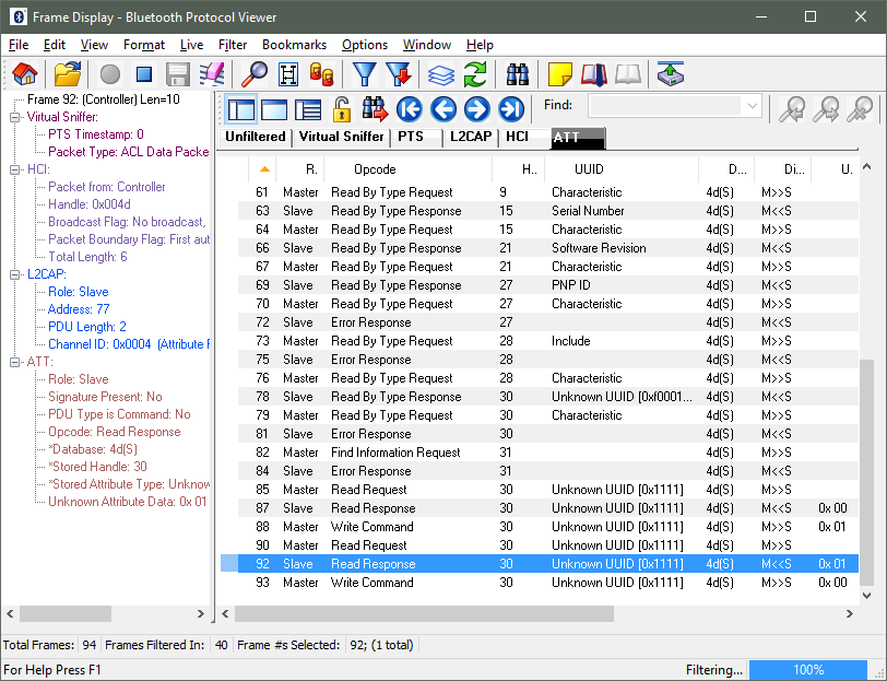
Note that the handle for the Characteristic Value attribute for the LED0 Characteristic is `30` just like in the Device Monitor screenshot earlier.
Making a Virtual Client Script
-----------------------------
Virtual Client Script functionality is found in the `WORKBENCH` view of Bluetooth Developer Studio.
If you click on the `SCRIPT` button, you will get a default template script which is a good starting point for testing.
When you start the workbench session, the log output for the `Virtual Client` will tell you how you can access the services and characteristics in your project
```text
15.05 - [Emulation] [V] - Mapping Constants For Services & Characteristics
15.05 - [Emulation] [V] - ----------------------------------
15.05 - [Emulation] [V] - SERVICE_LED_SERVICE = F0001110-0451-4000-B000-000000000000
15.05 - [Emulation] [V] - LED_SERVICE_LED0 = F0001111-0451-4000-B000-000000000000
15.05 - [Emulation] [V] - ----------------------------------
15.05 - [Emulation] [V] - ----------------------------------
15.05 - [Emulation] [V] - SERVICE_BUTTON_SERVICE = F0001120-0451-4000-B000-000000000000
15.05 - [Emulation] [V] - BUTTON_SERVICE_BUTTON0 = F0001121-0451-4000-B000-000000000000
15.05 - [Emulation] [V] - ----------------------------------
``` **Virtual Client log** – Here only LED0 and BUTTON0 are added, following the instructions above
If you just click on the `Play` button without changing the script, the log output will tell you how you should add reads and writes. So that is what we will do now.
* Click on `SCRIPT`
* Find the `readList` variable
* Add a line inside the array: `[SERVICE_BUTTON_SERVICE, BUTTON_SERVICE_BUTTON0],`
* Find the `writeList` variable
* Add a line inside the array: `[SERVICE_LED_SERVICE, LED_SERVICE_LED0, 1],`
* Find the `notifyList` variable
* Add a line inside the array: `[SERVICE_BUTTON_SERVICE, BUTTON_SERVICE_BUTTON0, [1, 0]],`
* Find a line in the function `CharacteristicValueChangedNotify` near that bottom that says `logNotification.splice(i, 1);` and comment out this line to get log output for each notification, and not just the first one.
* Click `Save` and `Done`
When you now press the Play button, if you are connected, you should see the LED being turned on and notifications enabled for the button so that each time you press it, you get a notification
### Interactive script
There are many things you can do with this script, but for now we are just going to add a write to `LED0` whenever `BUTTON0` is pressed.
When a notification is recieved, the function `CharacteristicValueChangedNotify` is called by the back-end. We will insert a snippet here that checks if it was `BUTTON0` and if so, send the same value to `LED0`.
```js
function CharacteristicValueChangedNotify(characteristic)
{
// ...
var btnService = DeviceContext.GetService(SERVICE_BUTTON_SERVICE);
var btn0Char = btnService.GetCharacteristic(BUTTON_SERVICE_BUTTON0);
if (characteristic.UUID == btn0Char.UUID)
{
log("FUN: Send a new value to LED0.")
// Get the value of the notified characteristic
var notiValue = DeviceContext.GetValue(characteristic);
// Write it to LED0
testWriteCharacteristic(SERVICE_LED_SERVICE, LED_SERVICE_LED0, notiValue[0]);
}
return;
}
``` **script** – Add the above code right before `return`
After you add this and restart the script, you should see the LED change state when you press and release the button.
References
==================================
[Bluetooth SIG]
[SIG GATT Profiles Overview]
[Bluetooth Interoperability and Profiles]
[Bluetooth Developer Studio]
[BDS Plugins]
<!-- Actual references -->
[Bluetooth SIG]: https://developer.bluetooth.org/AboutUs/Pages/default.aspx
[SIG GATT Profiles Overview]: https://developer.bluetooth.org/TechnologyOverview/Pages/Profiles.aspx#GATT
[SIG GATT Overview]: https://developer.bluetooth.org/TechnologyOverview/Pages/GATT.aspx
[Bluetooth Interoperability and Profiles]: https://developer.bluetooth.org/DevelopmentResources/Pages/Custom-Profile-Development.aspx
[Bluetooth Developer Studio]: https://www.bluetooth.com/~/media/developer-studio/index
[BDS Plugins]: https://www.bluetooth.com/develop-with-bluetooth/developer-resources-tools/bluetooth-developer-plugins