Functional Description
This chapter describes the functionality of the packet sniffer firmware.
Control States
The figure below shows the main control states of the Sniffer firmware:
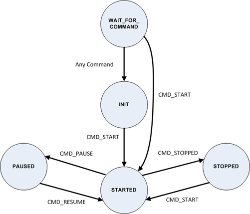
Fig. 17 Packet Sniffer FW Control States
WAIT_FOR_COMMAND
Enter Condition: This state is entered after boot/startup of the sniffer FW.
Description: In this state the device will blink an LED and output a message to the serial interface as shown in Figure 3 once per second. The message includes information about the FW version.
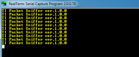
Fig. 18 Output message on serial interface in WAIT_FOR_COMMAND state
INIT
Enter Condition: When in the WAIT_FOR_COMMAND state, any successful command received from host will switch state to INIT, except for CMD_START which will switch state to STARTED.
Description: The LED blinks and messages on the UART that is output in the WAIT_FOR_COMMAND state stops.
STARTED
Enter Condition: CMD_START is received when in either WAIT_FOR_COMMAND, INIT or STOPPED state, or CMD_RESUME is received when in PAUSED state.
Description: The radio is set in RX mode. Packets received over air are forwarded to host.
STOPPED
Enter Condition: CMD_STOP is received when in STARTED state.
Description: The radio RX mode is stopped. The timestamp counter is reset.
PAUSED
Enter Condition: CMD_PAUSE is received when in STARTED state.
Description: The radio RX mode is stopped. The timestamp counter is NOT reset.
Firmware Architecture
Fig. 19 illustrates the architecture of the packet sniffer FW.
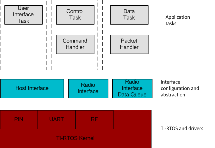
Fig. 19 FW Architecture
At the bottom of the figure are TI-RTOS and drivers. This software layer is not described further in this document.
Interface configuration and abstraction
Above the TI-RTOS and drivers is a layer with interface configuration and abstraction.
The purposes of this software layer are:
- Hide interface specific details. For example hide the details on how to configure the radio, radio queue handling etc.
- Provide a simpler interface for the sniffer FW application.
- Allow easier testing of packet sniffer application functionality.
Application tasks
The application consists of three separate RTOS tasks.
Control Task The control task is the highest priority task in the system. This task controls the application state and handles commands received from the host (on the host interface).
This task is blocked until there is data received on the host interface. If the received data is a valid command it will handle the command accordingly and may change the application control state.
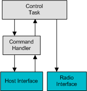
Fig. 20 Control Flow
Fig. 20 is a simplified illustration of the control flow. The command handler handles data received on the host interface. If the data is a valid command it forwards the command to the control task. The control task sets control state and configures the radio interface according to the command. The command handler sends a command response on the host interface depending on the status of the command handled.
Note that function calls between the control task and the command handler, host interface and radio interface all runs in the context of the control task.
User Interface Task
The user interface task has lower priority than the control task, but higher priority than the data task. The user interface task only runs in the WAIT_FOR_COMMAND control state (see Fig. 17). Hence it never runs when the radio is in receive mode. This task is terminated when the control state is changed to one of the other states.
The user interface task blinks an LED and outputs a user message on the host interface (see also description of the WAIT_FOR_COMMAND state).
Data Task
The data task is the lowest priority task in the system. When in the STARTED state the only tasks running are the control task and the data task.
The data task continuously polls the radio interface data queue for incoming packets. If there is an incoming packet on the radio interface it wraps the radio data as payload in a host interface packet and forwards it on the host interface.
While the packet is written on the host interface this task is blocked.
Note that the function calls between the data task and the radio interface data queue, the packet handler and the host interface all run in the context of the data task.
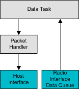
Fig. 21 Data Flow
Fig. 21 illustrates the flow of data from the radio to the host interface.