8.3. MCU1_0 Application Development with SYSFW
8.3.1. Introduction
Starting with Processor SDK 7.1, the following System Firmware (SYSFW) components on this device are required to run on the MCU1_0 core of the MCU Subsystem instead of the DMSC core:
System Controller Interface Server (SCISERVER)
Resource Management (RM) Services
Power Management (PM) Services
These components make up the Device Manager (DM) role of SYSFW. The software stack view of these components can be seen in section Architecture Change between SDK 7.0 and SDK 7.1.
This architecture has two important requirements for MCU1_0 developers to be aware of:
Applications running on MCU1_0 need to:
ensure that the associated libraries are properly linked into the MCU1_0 firmware image build
call the associated initialization functions to start these services.
Refer to section MCU1_0 Application Requirement Details for more details.
Bootloaders
If using SPL/uboot, the tispl.bin generation step is now dependent on the compiled MCU1_0 firmware image. So each time the MCU1_0 image is regenerated, the tispl.bin also need to be regenerated as part of the build flow.
Bootloaders must read the board configuration from the boot media as before and also leave the board configuration at a predefined location to allow the MCU1_0 application containing the SCISERVER to read the board configuration and initialize RM and PM.
Refer to section SPL/uboot Loading for more details.
Warning
These system firmware components are foundational services which all cores on the SoC depend on. Consequences of building the system without proper integration of these components running on the MCU1_0 may result multiple run-time failures, including failure to boot.
The purpose of this document is to guide MCU1_0 developers on details for how to satisfy the above two requirements.
The TI Foundational Security (TIFS) software continues to run on the DMSC in Processor SDK 7.1 as well.
The following table highlights the variations of where the RM and PM execute versus the TI Foundational Security on the different K3 family of devices.
Device |
TI Foundation Security |
3rd Party HSM/SHE stack |
RM/PM, SCI Server |
|---|---|---|---|
AM65x/ DRA80x, AM64x |
DMSC (M3 based) |
NA |
DMSC (M3 based) |
J721E, J7200 |
DMSC (M3 based) |
DMSC (M3 based) |
Library on MCU R5* |
J721S2 |
SMS (M4 based) |
SMS (M4 based) |
Library on MCU R5* |
More details related to these System Firmware components, and its role in the overall system architecture can be found at TISCI Introduction.
The rest of this document is applicable only to devices where the RM/PM and SCI server execute on MCU_R5F.
8.3.1.1. Audience
Primary: Developers working on application firmware on MCU1_0.
Secondary: Developers responsible for build flow generation of SPL bootloader : (tispl.bin)
8.3.1.2. Motivation
This System Firmware architecture is motivated by the following points:
Secure Hardware Security Module (HSM) functions can run on a DMSC Security Island. The Security Island is responsible to execute TI foundational security software which enables use of TI’s hardware security features and HSM software stack which enables other software/system specific security features.
Enable MCU Only mode with HSM functions on DMSC. In the MCU only mode a typical software stack can have the AUTOSAR functioning on the MCU R5F and the security HSM stack can run on the DMSC allowing the customer to have MCU only mode of operation with security features enabled.
Lockstep Safety R5F runs safety critical PM & RM functions. PM and RM influence the safe operation of the device. Hence having these run on a lock step R5F helps the overall system safety goal.
Software security functions can also be run on dedicated R5F core but this is not recomended as the whole R5F core needs to be then dedicated for security operations. Having the HSM run on the DMSC allows to free up the R5F and also enables better utilization of the DMSC security island.
Note, customers are recommended to work with their desired Third Party to develop the HSM and full security solution on the DMSC. TI provides only the TI Foundational Security Software.
Further details about the motivation of this architecture can be found at Architecture Change between SDK 7.0 and SDK 7.1.
8.3.2. MCU1_0 Application Requirement Details
The introduction referred to MCU1_0 Application requirements. This section gives the specific details as to these requirements.
8.3.2.1. Libraries to Link
All MCU1_0 applications should link the first three device manager related libraries in the table below. These libraries are provided as a part of PDK.
In the following table, SCI_PATH=”pdk_<soc>_<version>/packages/ti/drv/sciclient”
Library Name |
Library Path |
Include Header |
Description |
|---|---|---|---|
sciserver_tirtos |
$(SCI_PATH)/lib/<soc>/mcu1_0/<profile>/sciserver_tirtos.aer5f |
$(SCI_PATH)/sciserver_tirtos.h |
Applicable when RTOS is executing on the MCU1_0 |
sciclient_direct |
$(SCI_PATH)/lib/<soc>/mcu1_0/<profile>/sciclient_direct.aer5f |
$(SCI_PATH)/sciclient.h |
Direct function calls to RM/PM HAL services. Applicable to baremetal, TI-RTOS or other OS based applications. |
rm_pm_hal |
$(SCI_PATH)/lib/<soc>/mcu1_0/<profile>/rm_pm_hal.aer5f |
NA - Always call via sciclient APIs. |
Actual implementation of the RM/PM HAL operations. Applicable to baremetal, TI-RTOS or other OS based applications. |
sciserver_baremetal |
$(SCI_PATH)/lib/<soc>/mcu1_0/<profile>/sciserver_baremetal.aer5f |
$(SCI_PATH)/sciserver.h |
This is the bare-metal barebones functions of Sciserver. Note you cannot run sciserver without an OS. The application developer must develop their own version of $(SCI_PATH)/src/ sciserver/sciserver_tirtos.c for the OS you are using before working with Sciserver on the MCU1_0. |
8.3.2.2. Functions to Call
The typical set of APIs to be called by the application are given in the example file: pdk_<soc>_<version>/packages/ti/drv/sciclient/examples/sciserver_testapp/sciserver_testapp_main.c.
The sequence is explained here for reference:
Sciclient initialization parameters are required for the Sciclient direct interface for MCU1_0 applications.
Sciclient_ConfigPrms_t clientPrms;
Sciserver initialization parameters are required for the Sciserver RTOS based applications. Note for other OSes the appPrms will be corresponding to your own implementation of the sciserver_tirtos.c file.
Sciserver_TirtosCfgPrms_t appPrms;
The first API that needs to be called for initializing the default configuration of the Sciclient and Sciserver is as given below. If this step passes, then the code must proceed to read the board configuration left behind by the SBL. To know more about the board configuration passing between SBL/SPL to the MCU1_0 application please refer Board configuration passing between SPL/SBL and MCU1_0 applications.
By default the Sciserver task is kept at a task priority of 3 - High priority task and 1 - Low priority task. Refer pdk_<soc>_<version>/packages/ti/drv/sciclient/sciserver_tirtos.h One can change this value after the default initialization.
ret = Sciclient_configPrmsInit(&clientPrms);
ret = Sciserver_tirtosInitPrms_Init(&appPrms);
The Sciclient_boardCfgParseHeader should then be called to parse the content left behind by the SPL/SBL and populate the address for board configurations for the RM/PM services. To know more about the Board configurations which TISCI needs please refer TISCI Board Configuration.
The address at which the common board configuration is set is given in Board configuration passing between SPL/SBL and MCU1_0 applications.
#define SCISERVER_COMMON_X509_HEADER_ADDR (0x41cffb00)

ret = Sciclient_boardCfgParseHeader(
    (uint8_t *) SCISERVER_COMMON_X509_HEADER_ADDR,
    &clientPrms.inPmPrms, &clientPrms.inRmPrms);
The Init APIs should then be called to initialize the Sciclient and also perform the board configuration for RM and PM. The Sciserver_tirtosInit will set up the Tasks and HWIs needed for the servicing of non-secure messsages for RM and PM.
ret = Sciclient_init(&clientPrms);
ret = Sciserver_tirtosInit(&appPrms);
After BIOS_start is called the Sciserver task would start.
BIOS_start();
For other cores, post this point the Sciserver on MCU1_0 will be ready to receive and service messages. This can be checked from other cores by requesting for a get version on a non-secure Secure Proxy queue. The Get version message can be sent via TISCI_MSG_VERSION message.
8.3.2.3. Memory Map Considerations
The application developer should also account for memory locations reserved for passing board configuration from SBL/SPL to the application on MCU1_0.
Address |
Size |
Purpose |
Persistence |
|---|---|---|---|
0x41C0_0000 |
512 KB |
Hold SPL/SBL Image |
Only during SPL/SBL execution. Can be claimed once MCU1_0 app is jumped to. |
0x41C8_0000 |
8 KB |
Hold the Board configuration passed between SPL/SBL and SCISERVER_APP |
Can be claimed once MCU1_0 app executes Sciclient_init on MCU1_0 |
0x41C8_2000 |
502 KB |
Loadable application on OCMS RAM (including SCISERVER) |
Through out MCU1_0 app execution |
0x41cf_fb00 |
~1.2 KB |
Common header used in ROM combined image format as well. |
Can be claimed once MCU1_0 app executes Sciclient_init on MCU1_0 |
For more details on the sections of memory and their usage refer Board configuration passing between SPL/SBL and MCU1_0 applications.
8.3.3. MCU1_0 Loading Scenarios
This section details key care-abouts depending on the specific boot loading scenario of interest.
8.3.3.1. CCS Loading
8.3.3.1.1. Using PDK, MCUSW Examples
In order to load examples via CCS the following sub usecases should be kept in mind.
- Loading Applications on MCU1_0
When loading applications on the MCU1_0 the Sciclient_direct (in baremetal case and TI RTOS case) and Sciserver (in TI RTOS case) are assumed to be a part of the MCU1_0 application. Use the pdk/packages/ti/drv/sciclient/tools/ccsLoadDmsc/<soc>/launch.js file as descibed in LINK to launch the TIFS on the DMSC M3 and run the board configuration for the secure proxy setup and the security board configuration via sciclient_ccs_init app.
A special configuration flag has been added to the `launch.js` file `loadSciserverFlag`. The default value of this flag is 1. When running your own application on the MCU1_0, please make sure to change this flag to 0.
- For other cpus
When loading applications on other CPU cores apart from MCU1_0 which link the sciclient library which sends the TISCI messages over secure proxy use the launch.js file to load the TIFS on the DMSC M3, run the common and security board configuration via the sciclient_ccs_init app and then load the sciserver_testapp on the MCU1_0.
The MCU1_0 is left at the main() function of the sciserver_testapp before giving control back to the user. At this point one can load the non MCU1_0 core with the application of interest and then run both the MCU1_0 and the application core of choice.
A special configuration flag has been added to the `launch.js` file `loadSciserverFlag`. The default value of this flag is 1. When running your own application on the non-MCU1_0 core, please make sure to keep this flag as 1.
8.3.3.2. SBL Loading
When loading via SBL, the SBL will load the binaries corresponding to the application core which has the appropriate images in the AppImage file in SD Card, or flashed in OSPI, or sent via UART. In the case of MCU1_0 applications, the AppImage should contain the binary corresponding to the MCU application the developer has built along with the sciclient_direct, sciserver, rm_pm_hal libraries.
In the case of non MCU1_0 applications, in case the developer has no application running on MCU1_0, they must load the sciserver_testapp on the MCU1_0 core. If they have an application running on the MCU1_0, they must integrate the sciclient_direct, sciserver, rm_pm_hal libraries and also call the set of APIs from their MCU1_0 app. In summary, an MCU1_0 application is mandatory with an OS running when there are multiple cores.
In the PDK examples, the makefile is setup to always include the MCU1_0 sciserver_testapp_mcu1_0_release.rprc image in the Appimage if the MCU1_0 app is not present.
SBL by itself links the sciclient_direct and the rm_pm_hal libraries to be able to initialize the system.
The TI Foundational Security (TIFS) security code loading to the DMSC remains the same as it was before. API calls to the processor boot and security services remain the same as what it was before.
8.3.3.2.1. Using PDK, MCUSW Examples
The top level Sciclient_* APIs remain the same for the applications. The only careabout PDK applications should consider are:
PM/RM service will need to be integrated in the example itself for MCU1_0 applications
For other non MCU1_0 applications there is no change (Need to load MCU R5F now to run Sciserver.)
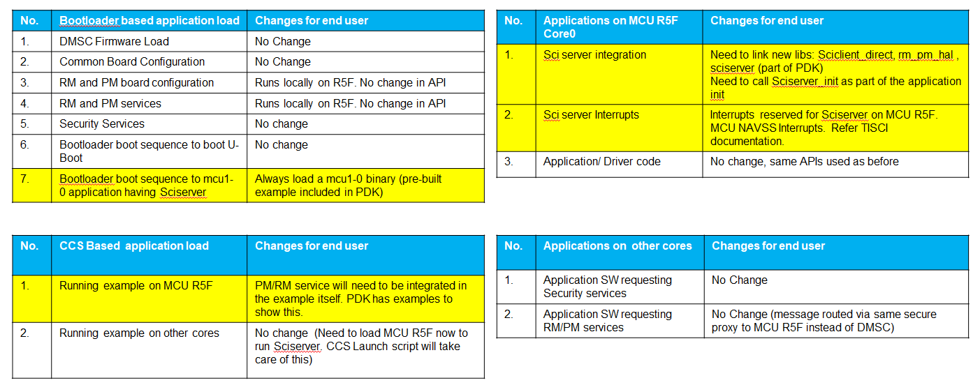
Fig. 8.1 Software Impact for Applications
8.3.3.2.2. Using QNX Filesystem + Vision Apps
The QNX SBL boot flow uses the boot app on the MCU1-0 (located at mcusw/mcuss_demos/boot_app_mcu_rtos/). The boot app has been updated to run Sciserver.
8.3.3.3. SPL/uboot Loading
As mentioned in the introduction, when using SPL/uboot, the tispl.bin generation step is now dependent on the compiled MCU1_0 firmware image. So each time the MCU1_0 image is regenerated, the uboot and tispl.bin also need to be regenerated as part of the build flow. Likewise, if the uboot or tispl.bin need to be rebuilt, then the user needs to pass the appropriate MCU1_0 firmware image to the uboot build command.
The MCU1_0 image is passed to the uboot make command via the “DM” variable on the make command, as shown in the highlighted line below.
 $(MAKE) -C $(PSDK_LINUX_PATH)/board-support/u-boot-* ARCH=arm CROSS_COMPILE=$(GCC_LINUX_ARM_ROOT)/bin/aarch64-none-linux-gnu- \
                                                      O=j721e-arm64-linux -j8 j721e_evm_a72_defconfig
 $(MAKE) -C $(PSDK_LINUX_PATH)/board-support/u-boot-* ARCH=arm CROSS_COMPILE=$(GCC_LINUX_ARM_ROOT)/bin/aarch64-none-linux-gnu- \
                                                      ATF=$(PSDK_LINUX_PATH)/board-support/prebuilt-images/bl31.bin \
                                                      TEE=$(PSDK_LINUX_PATH)/board-support/prebuilt-images/bl32.bin \
                                                      DM=$(FIRMWARE_PATH)/ipc_echo_testb_mcu1_0_release_strip.xer5f \
                                                      O=j721e-arm64-linux
Note
The image passed to the “DM” parameter when building uboot must match the corresponding firmware image located in the linux filesystem at the following path:
/lib/firmware/j7-mcu-r5f0_0-fw
This is needed because linux needs to extract the resource table information from the image.
Warning
If the /lib/firmware/j7-mcu-r5f0_0-fw image (or soft link to the image) is missing or does not match the image passed to the “DM” parameter when building uboot, the kernel may boot fine, but applications trying to communication via IPC between Linux and MCU1_0 may fail to synchronize and communicate.
8.3.3.3.1. Using SDK Default Linux Filesystem
By default, the file system that comes in the Processor SDK Linux package has simple echo test firmware built using the RTOS PDK for each RTOS core as shown below. The highlighted line corresponds to the MCU1_0 firmware which already includes the SCISERVER and RM/PM services.
 j7-c66_0-fw -> pdk-ipc/ipc_echo_test_c66xdsp_1_release_strip.xe66
 j7-c66_1-fw -> pdk-ipc/ipc_echo_test_c66xdsp_2_release_strip.xe66
 j7-c71_0-fw -> pdk-ipc/ipc_echo_test_c7x_1_release_strip.xe71
 j7-c71_1-fw -> pdk-ipc/ipc_echo_test_c7x_2_release_strip.xe71
 j7-main-r5f0_0-fw -> ethfw/app_remoteswitchcfg_server_strip.xer5f
 j7-main-r5f0_1-fw -> pdk-ipc/ipc_echo_test_mcu2_1_release_strip.xer5f
 j7-main-r5f1_0-fw -> pdk-ipc/ipc_echo_test_mcu3_0_release_strip.xer5f
 j7-main-r5f1_1-fw -> pdk-ipc/ipc_echo_test_mcu3_1_release_strip.xer5f
 j7-mcu-r5f0_0-fw -> pdk-ipc/ipc_echo_testb_mcu1_0_release_strip.xer5f
 j7-mcu-r5f0_1-fw -> pdk-ipc/ipc_echo_test_mcu1_1_release_strip.xer5f
The default uboot and tispl.bin file in the boot partition of the Processor SDK Linux were built by passing this image to the DM variable of the uboot make command line as shown in SPL/uboot build command example
So, as long as the user is not needing to rebuild uboot or change the MCU1_0 firmware from the default, then the default MCU1_0 firmware and uboot and tispl.bin can be used while changing other firmware without any issues.
8.3.3.3.2. Using Vision Apps for Linux and QNX SPL Boot
By default, the Processor SDK RTOS package uses the default MCU1_0 firmware from the Processor SDK Linux, as shown in Contents of /lib/firmware folder. The vision_apps demos rely primarily on OpenVX HWA nodes running on the the main domain r5fs (MCU2_0 & MCU2_1), and TIDL and DSP acceleration running on the DSPs. This way, if customizations are made to the vision_apps firmware without needing to develop on the MCU1_0, then there should be no need to rebuilt the uboot or MCU1_0 firmware.
However, for those who would like to have apps running on MCU1_0, the vision_apps makefiles can easily accomodate this option. The following are the additional steps required beyond the standard build steps outlined in the vision_apps documentation.
Download and install the Processor SDK Linux package.
By default, the installer extracts the package into the /home/$(USER) folder. If you decide to install it into a different location, be sure to update the PSDK_LINUX_PATH variable in the vision_apps/vision_apps_tools_path.mak file.
This is needed to get access to dependencies needed to rebuild uboot
Turn on the BUILD_CPU_MCU1_0 build flag from “no” to “yes” in the vision_apps/vision_apps_build_flags.mak
BUILD_CPU_MCU1_0?=yes
Beyond this, simply follow the rest of the steps in the vision_apps build and run guide. The makefiles will build both MCU1_0 example image and uboot, and the sd card install steps will also load both of these if the BUILD_CPU_MCU1_0 build flag is set to “yes”.
The source code for the MCU1_0 application that comes with vision_apps is located at the following path:
vision_apps/apps/basic_demos/app_tirtos/tirtos_linux/mcu1_0/main.c
As of now, it doesn’t do much beyond serving as a starting point example. As expected for MCU1_0 application firmware, it does link and run the SCISERVER, and RM/PM services for the SoC.
8.3.4. MCU1_0 Application Migration to 7.1
8.3.4.1. Vision Apps Diff file
For those who are interested in understanding how vision apps adapted to this SYSFW architecture upgrade from 7.0 to 7.1, we have provided a diff file of relevant changes in the vision apps component related to this migration. This can be used as a reference to better understanding changes that may need to be done in a custom application.
8.3.4.2. Enabling Sciserver Debug Logs
If it is required to debug issues with the Sciserver, logging can be enabled to provide details as to the issue being faced. However, please note that the logging mechanism described below should not be used when using the vision apps build of MCU1_0 as it causes issues when running the MCU1_0 application.
In order to enable Sciserver logs, please set the VERBOSE macro to 1 in the file pdk/packages/ti/drv/sciclient/src/sciserver/sciserver.c and rebuild for Sciserver logs on MCU UART.
/* Set VERBOSE to 1 for trace information on message routing */
#define VERBOSE 0

#if VERBOSE
#include <ti/drv/uart/UART_stdio.h>
#define Sciserver_printf UART_printf
#else
#define Sciserver_printf(...)
#endif
If you are using sciserver_testapp then the re-built sciserver_testapp should be copied to the following location replacing the following files.
pdk/packages/ti/drv/sciclient/tools/ccsLoadDmsc/<soc>/sciserver_testapp_mcu1_0_release.rprc
pdk/packages/ti/drv/sciclient/tools/ccsLoadDmsc/<soc>/sciserver_testapp_mcu1_0_release.xer5f
The make command for the sciserver_testapp is:
make -j -s sciserver_testapp BOARD=<name of evm>
Please make sure you are enabling UART before sciserver is initialized when using the VERBOSE option.
8.3.5. Board configuration passing between SPL/SBL and MCU1_0 applications
SBL/SPL reads the board configuration from the boot media. The SCISERVER also requires the board configuration data for setting up the RM and PM services. Hence the SPL/SBL needs to keep the board configuration data in an aligned memory location with a header which the SCISERVER can later read, check the header and if it finds the header, parse the board configuration and process it.
The main responsibilities for the SBL/SPL are:
Read the board configuration from the boot media.
Copy or store the configuration using the format shown Here
Run the TIFS board configurations (Common board config and Security Board configuration)
The main responsibilities of the SCISERVER APP are:
Look for the magic word in the aligned address.
If the magic word matches, board configuration data is present and then read the board configuration address offsets
Configure the config parameters for Sciclient init for the board configuration.
The flow is as below:
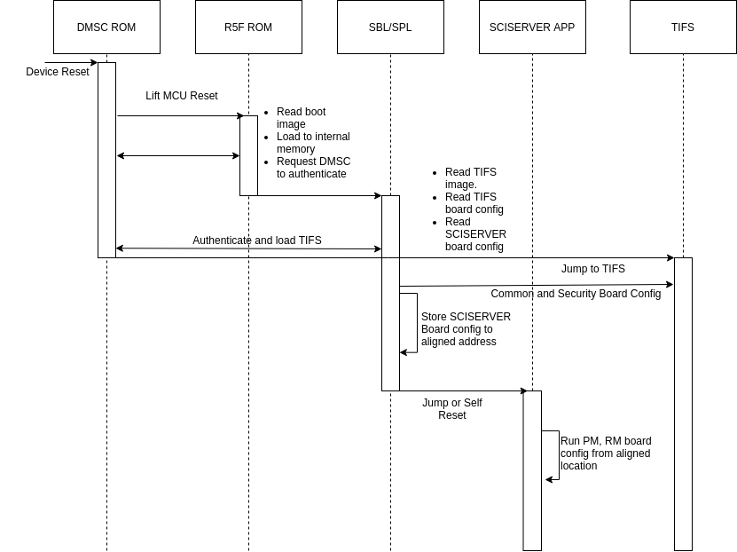
Fig. 8.2 Board configuration passing from SBL/SPL to SCISERVER
The format for the structure which is passed between SBL/SPL and the SCISERVER has 3 parts:
Common Header
Board Configuration Header
Board Configuration
The Common Header format is as below:
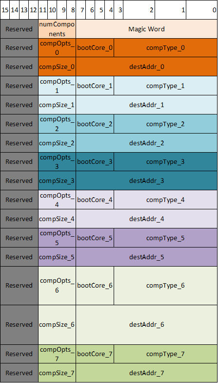
Fig. 8.3 Common Header Format
The Board configuration Header format is as below:
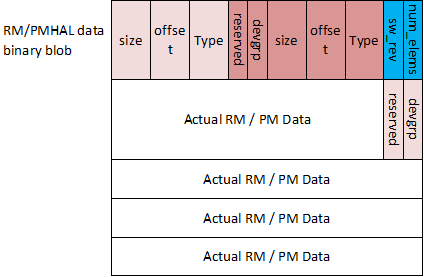
Fig. 8.4 Board Configuration Header Format
The code version of the same formats are as below:
/**
 * \def EXTBOOT_X509_MAGIC_WORD_LEN
 * Length of magic word for extended boot info table.
 *
 * \def EXTBOOT_X509_MIN_COMPONENTS
 * Minimum number of components that should be present in combined image.
 *
 * \def EXTBOOT_X509_MAX_COMPONENTS
 * Max number of components in extended boot info table.
 *
 * \def EXTBOOT_X509_ROM_INFO_BASE
 * Base address where ROM loads the extended boot info.
 *
 * \def EXTBOOT_X509_COMPTYPE_SYSFW_DATA
 * Component type corresponding to SYSFW data blob.
 */
#define EXTBOOT_X509_MAGIC_WORD_LEN             (8)
#define EXTBOOT_X509_MIN_COMPONENTS             (3)
#define EXTBOOT_X509_MAX_COMPONENTS             (8)
#define EXTBOOT_X509_COMPTYPE_SYSFW_DATA        (0x12)

/**
 * \def EXTBOOT_X509_MAGIC_WORD
 * Magic word that specifies whether combined image is being used.
 */
const u8 EXTBOOT_X509_MAGIC_WORD[EXTBOOT_X509_MAGIC_WORD_LEN] = { 'E', 'X', 'T', 'B', 'O', 'O', 'T', 0 };

/**
 * \brief Component information populated by ROM. The combined image has multiple components.
 *                  ROM populates this information for each component.
 *
 * \param comp_type Type of component
 * \param boot_core Core that loads or runs image
 * \param comp_opts Component options. Not used for now.
 * \param dest_addr Image destination address
 * \param comp_size Size of the component in bytes
 */
struct extboot_x509_comp {
    u32 comp_type;
    u32 boot_core;
    u32 comp_opts;
    u64 dest_addr;
    u32 comp_size;
};

/**
 * \brief Component information table populated by ROM.
 *
 * \param magic_word Magic word for extended boot
 * \param num_comps Number of components present in extended boot info table
 * \param comps Information for each component
 */
struct extboot_x509_table {
    u8              magic_word[EXTBOOT_X509_MAGIC_WORD_LEN];
    u32             num_comps;
    struct extboot_x509_comp    comps[EXTBOOT_X509_MAX_COMPONENTS];
};

/**
 * \brief Describes the board config data
 *
 * \param type Type of board config data. This should map to corresponding TISCI
 *      message type. For example, a PM boardcfg should have a descriptor
 *      type TISCI_MSG_BOARD_CONFIG_PM.
 * \param offset Offset for board config data from beginning of SYSFW data binary blob
 * \param size Size of board config data
 * \param devgrp Device group to be used by SYSFW for automatic board config processing
 * \param reserved Reserved field. Not to be used.
 */
struct extboot_boardcfg_desc {
    u16 type;
    u16 offset;
    u16 size;
    u8  devgrp;
    u8  reserved;
} __attribute__((__packed__));

/**
 * \def EXTBOOT_BOARDCFG_NUM_DESCS
 * Number of boardcfg data in SYSFW data blob.
 */
#define EXTBOOT_BOARDCFG_NUM_DESCS              (4)

/**
 * \brief Boardcfg descriptor table provided by system integrator
 *
 * \param num_elems Number of elements in board config table.
 * \param sw_rev SW revision populated by system integrator.
 * \param descs Array of board config descriptors
 */
struct boardcfg_desc_table {
    u8              num_elems;
    u8              sw_rev;
    struct extboot_boardcfg_desc    descs[EXTBOOT_BOARDCFG_NUM_DESCS];
} __attribute__((__packed__));
The memory map for where the board configuration is left behind is as below:
Address |
Size |
Purpose |
Persistence |
|---|---|---|---|
0x41C0_0000 |
512 KB |
Hold SPL/SBL Image |
Only during SPL/SBL execution. Can be claimed once MCU1_0 app is jumped to. |
0x41C8_0000 |
8 KB |
Hold the Board configuration passed between SPL/SBL and SCISERVER_APP |
Can be claimed once MCU1_0 app executes Sciclient_init on MCU1_0 |
0x41C8_2000 |
502 KB |
Loadable application on OCMS RAM (including SCISERVER) |
Through out MCU1_0 app execution |
0x41cf_fb00 |
~1.2 KB |
Common header used in ROM combined image format as well. |
Can be claimed once MCU1_0 app executes Sciclient_init on MCU1_0 |
Note
For devices on which the ROM supports the combined image format support where a single X509 certificate can be used to load the TIFS and the MCU1_0 SPL, the ROM leaves a header with the details of which image went where. The 0x41cf_fb00 is the address where this table is left. The design of the table for the common header and ROM left behind table is the same to make sure any subsequent apps see the same format accross J721E, J7200, J721S2 and future devices.
The choice of 0x41C8_0000 is to make sure multiple holes are not present in the loadable sections of the application.
Warning
Please make sure to use the board configuration in the MCU SRAM memory left behind by the SPL/SBL. Any other board configuration built into the MCU1_0 App should not be used. Also, if the board configuration is kept in any other memory apart from MCU SRAM the TIFS will crash. The TIFS is needed to authenticate the board configuration in HS devices. TIFS also uses the RM board configuration to set up channelized firewalls.