5. EVM Setup for J721E
This section is intended to give a quick reference of EVM related to SDK usage. Full EVM documentation can be referenced at TDA4VM & DRA829V system-on-module.
Important
The power supply current requires more than 1A @12V input
DisplayPort-to-DVI or DisplayPort-to-HDMI adapters don’t work with DisplayPort
The SOM board has to be tightly inserted into the connector sockets.
When connecting the fusion daughter card, the power cable connecting processor board and fusion board should look exactly like the picture in section Fusion daughter card. (P.S. The same cable from TDA2P EVM has the opposite wire connection at one end)
5.1. EVM Setup to run SDK demos
5.1.1. Daughter card requirements
Below table shows the daughter cards required for various features/demos
Feature |
Infotainment card |
Fusion 1 card |
IMX390+UB953 FPDLink sensors |
GESI card |
|---|---|---|---|---|
HDMI display |
REQUIRED |
na |
na |
na |
eDP (DisplayPort)display |
na |
na |
na |
na |
CSI2RX camera input |
na |
REQURIED |
REQURIED |
na |
CPSW9G (ETHFW) demos |
na |
na |
na |
REQUIRED |
CAN demos |
na |
na |
na |
REQUIRED |
5.1.2. UART terminal setup
Connect USB cable to Main UART port on common processor board (see Common Processor Board)
4 UART ports would be visible at the PC side
Port 0 from this is used this for Linux, RTOS UART terminal from A72
Setup UART for 115200 baud rate, 8 data bits, no party, 1 stop bit
5.1.3. Boot Modes
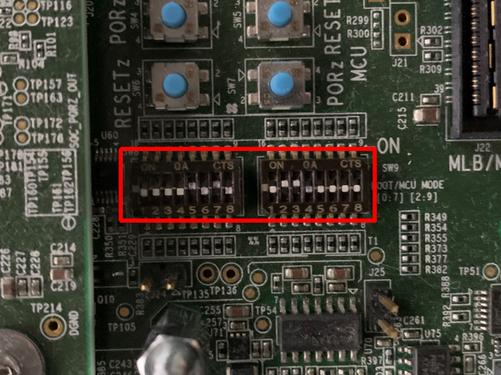
Bootmodes are selected using the SW8 and SW9 switches on the common processor board.
5.1.3.1. No Boot Mode
When you want the binaries to be loaded from a debugger (CCS), the common processor boards has to be set in the NO boot mode.
Following are the switch settings to do the same.:
SW8[1-8] = 1000 1000
SW9[1-8] = 0111 0000
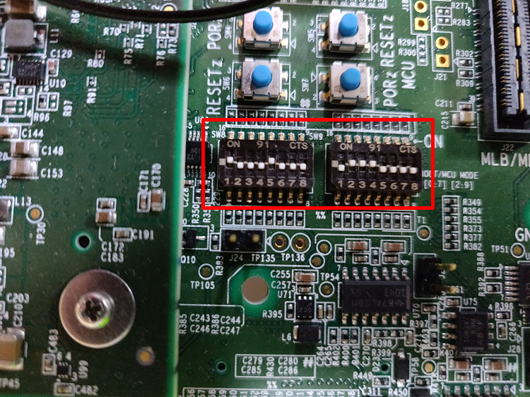
Fig. 5.1 No Boot Mode
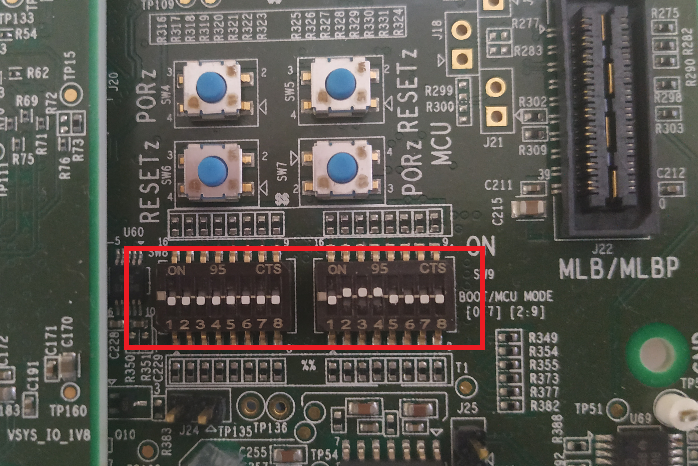
5.1.3.2. SD Boot Mode
Following are the switch settings to set the boot mode to SD for common processor board.:
SW8[1-8] = 1000 0010
SW9[1-8] = 0000 0000
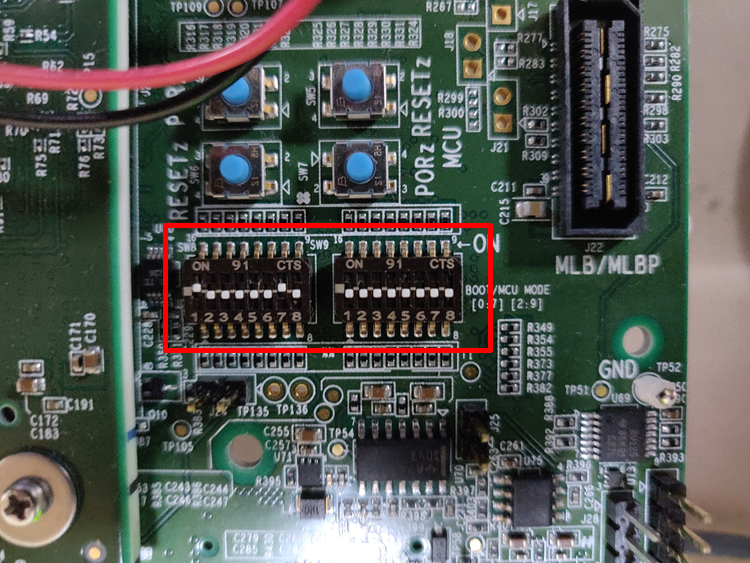
Fig. 5.2 MMC/SD Boot Mode
5.1.3.3. OSPI Boot Mode (J721E ES1.x versions only)
Following are the switch settings to set the boot mode to OSPI for common processor board.:
SW3[1-8] = 0xxx xxxx
SW8[1-8] = 0000 0000
SW9[1-8] = 0100 0000
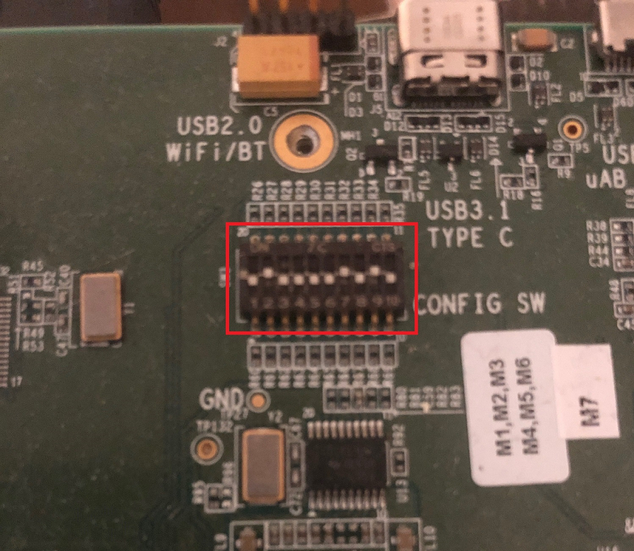
Fig. 5.3 OSPI Boot Mode SW3
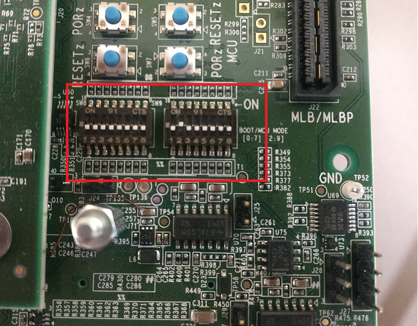
Fig. 5.4 OSPI Boot Mode SW8 and SW9
5.2. EVM and Daughter Card information
5.2.1. J721E SOM
The J721E Evaluation Module consists of a SOM (System on Module), shown in the red box below, fitted to a common processor board or base EVM.
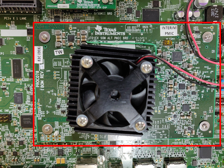
Fig. 5.9 J721E SOM
Contents of the board
J721E SoC
Power controller
4 GiB DDR RAM
OSPI NOR flash
Hyperflash
5.2.2. Common Processor Board
Common Processor Board is the main board which has peripherals to provide most common functionality. It has expander ports to connect to different adapter cards.
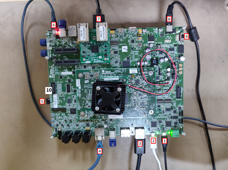
Fig. 5.10 J721E Common Processor Board
Contents of the board
4xUART to USB port for Main uarts
Port0 from this is used this for Linux, RTOS UART terminal from A72
2xUART to USB port MCU domain uarts
Port0 from this is used for DMSC UART
Port1 from this is used for MCU R5F UART
2x Display (eDP/DP) ports
Display0 is used by software for eDP/DP output
Ethernet (CPSW2G) port
SD card slot
XDS110 on board USB JTAG connector
USB ports
12V Power input
Power switch
MIPI JTAG connector
5.2.3. Infotainment daughter card
Infotainment daughter card is adapter board which has additional peripherals for infotainment use cases. This has support for HDMI display, FPDlink display extra audio channels.
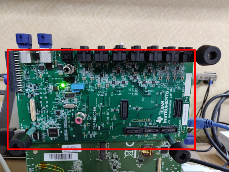
Fig. 5.11 Infotainment daughter card
Contents of the board
HDMI display connector
2x FPDlink display connectors
14x 3.5mm audio jacks
Parallel port Omnivision camera connector (direct connection, i.e no FPDLink)
CSI camera connector (direct connection, i.e no FPDLink)
5.2.4. Quad Port Ethernet daughter card
Quad Port Ethernet (QPENet) board is an adapter board which offers additional Ethernet port capabilities to the Jacinto7 EVM.
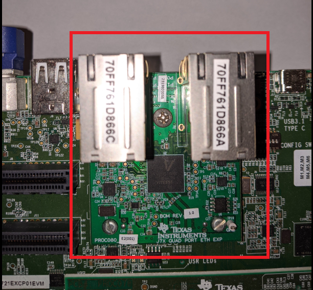
Fig. 5.12 QPENet daughter card
Contents of the board:
Quad-SGMII PHY
4x Ethernet ports
EEPROM with flashed MAC addresses
5.2.5. GESI daughter card
GESI(Gateway/Ethernet Switch/Industrial) daughter card is an adapter board which has additional peripherals for gateway and industrial use cases. This has support for extra Ethernet ports and CAN ports.
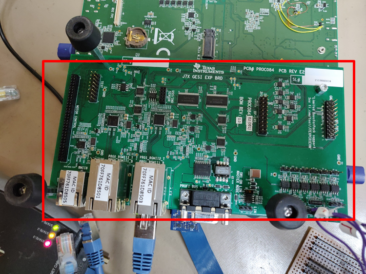
Fig. 5.13 GESI daughter card
Contents of the board
5x Ethernet ports
Profinet connector
Motor control headers
Additional CAN Transceivers/ headers
5.2.6. Fusion daughter card
Fusion daughter card is adapter board to connect 4 camera sensors (IMX390+UB953 serializer) through de-serializer (UB960) available on the Fusion1 daughter card to CSI2RX ports of J721E SoC.
Connect the daughter card to common processor board at “CSI2 Exp” connector J25.
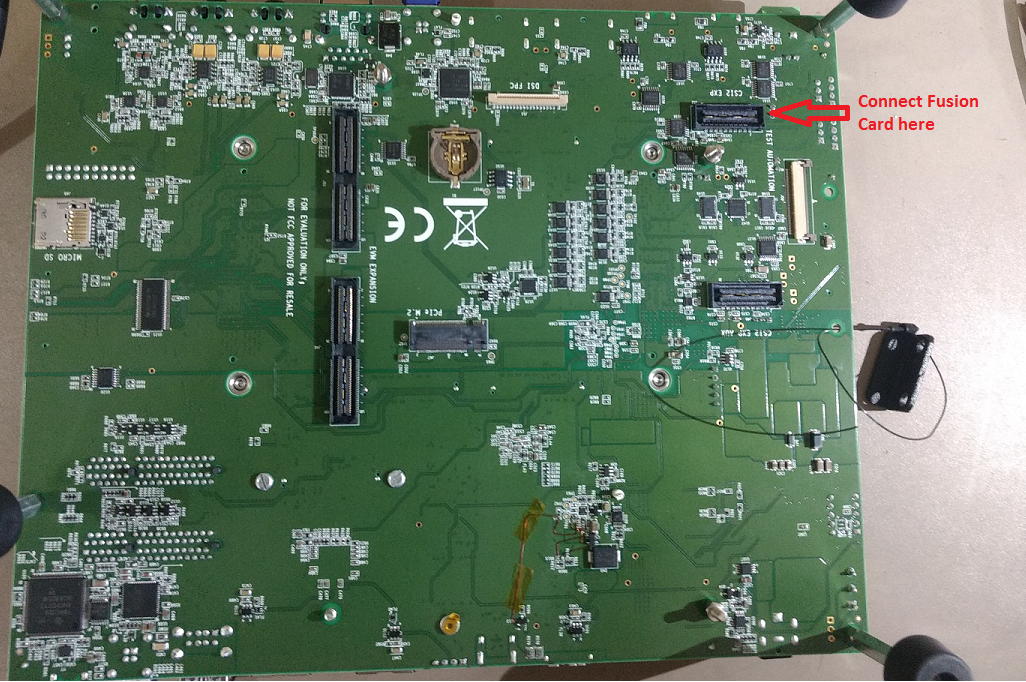
Fig. 5.14 CSI2 Exp Connector
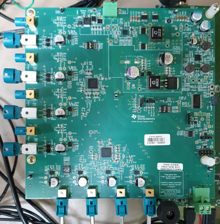
Fig. 5.15 Fusion1 Board
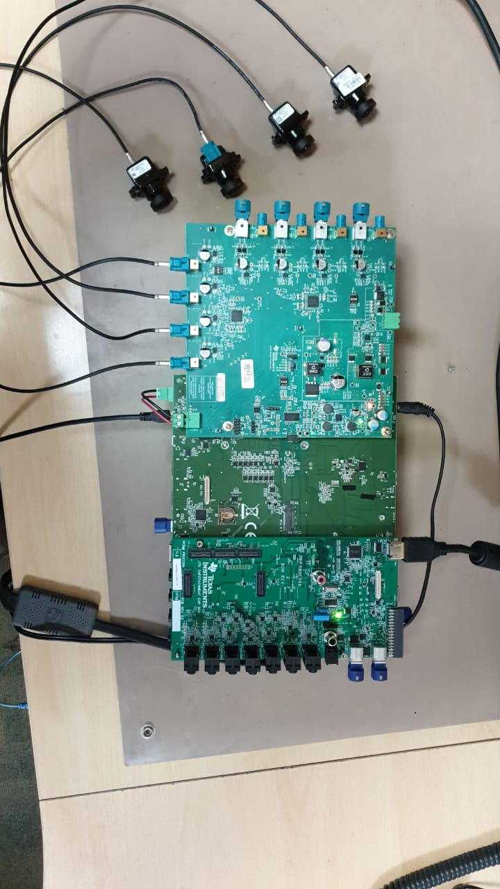
Fig. 5.16 Fusion1 Camera Setup