|
MCUSW
|
|
MCUSW
|
This application demonstrates the fast boot capability provided by the Octal SPI flash controller on J721E & J7200 SoCs. By default, it boots the main domain cores with basic applications, and also provides mechanisms to alternatively boot Linux or QNX on the MPU1_0 (i.e. A72) core. In addition, it demonstrates booting of the main domain cores via MMCSD media on J721E/J7200. The application performs the following actions:
This facilitates an early CAN response feature, typically required in an automotive ECU, followed by booting of the main domain cores on the SoC.
Please refer to the data sheets for early CAN response
This application depends on multiple components and are detailed in sections below
This application depends on the Secondary Boot Loader (SBL) component from Processor SDK RTOS. For further details on the SBL, please refer to the Platform Development Kit (PDK) documentation on the SBL component for this release.
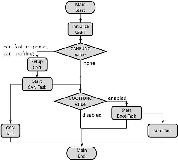
The following flow chart displays the main application on the MCU1_0, which can spawn up to 2 current tasks.
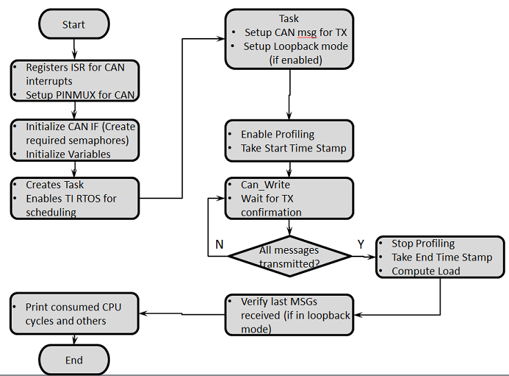
The following flow chart displays the functionality of the CAN task if the CAN function is set to "can_profiling".
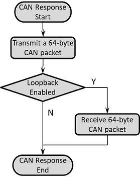
The following flow chart displays the functionality of the CAN task if the CAN function is set to "can_fast_response".
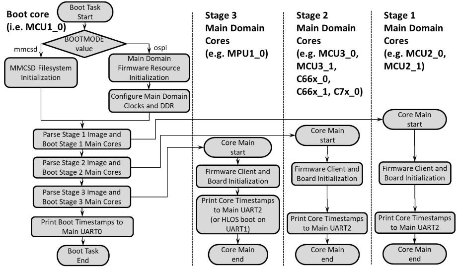
The following flow chart displays the functionality of the Boot task, as well as the applications started on the main domain cores.
The following flow chart displays the functionality of the Boot task when run along with BIST (as well as the applications started on the main domain cores). Note that the default build of this application disables the BIST thread shown below, and BISTFUNC flag must be enabled in the build for BIST to be run.
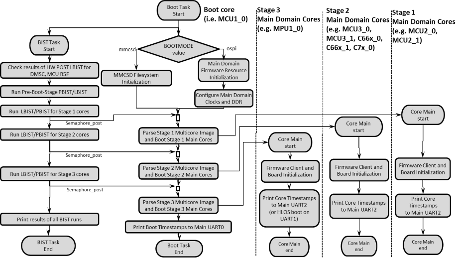
Enable/Disable Boot Task
The task that boots the main domain cores can be enabled/disabled. In the default boot sequence there are 3 stages for booting (J721E), or 2 stages (J7200). The specification of the cores to be included in each stage is given by the arrays "boot_order_first_stage", "boot_order_second_stage" and "boot_order_third_stage", found in mcuss_demos/boot_app_mcu_rtos/soc/$SOC/boot_core_defs.c. Below is the configuration flag for this feature.
Options are "enabled" (default) or "disabled".
Enable/Disable BIST Task (J721E only) The task that runs Logic BIST and Memory BIST prior to boot stages can be enabled/disabled. In the default BIST sequence, there is one "pre-boot" stage (for BIST sections that need to be run before booting any of the main domain cores) and 3 main stages where BIST is run for main domain cores prior to the Boot Task booting those particular cores. The specification of the cores to be included in each stage is given by the arrays "pbist_pre_boot_stage", "lbist_pre_boot_stage", "pbist_first_boot_stage", "lbist_first_boot_stage", "pbist_second_boot_stage", "lbist_second_boot_stage", "pbist_third_boot_stage", and "lbist_third_boot_stage" in mcuss_demos/boot_app_mcu_rtos/soc/$SOC/bist_core_defs.c. Care should be taken to ensure that BIST sections defined for the 3 main stages (in bist_core_defs.c) match those utilized by the Boot Task (in boot_core_defs.c). Note that BOOTFUNC must be set to "enabled" as well to use the BIST Task. Below is the configuration flag for this feature.
Options are "enabled" or "disabled" (default).
Boot Media
The boot task can either boot the main domain cores using an appimage located in OSPI or on an MMCSD card. Below is the configuration flag for this feature.
Options are "ospi" (default) or "mmcsd".
Note that if the "ospi" option is utilized, the custom Secondary Boot Loader (sbl_cust_img) is expected to load the MCUSW Boot Application. If the "mmcsd" option is used, the mmcsd Secondary Boot Loader (sbl_mmcsd_img) should be used to load the MCUSW Boot Application.
Boot Operating Systems for MPU1_0
The boot task, by default, will load example applications written for TI Real-Time Operating System (RTOS) for all main domain cores (including MPU1_0). Alternatively, Linux or QNX operating systems could be loaded on MPU1_0. Below is the configuration flag for this feature.
Options are "none" (default, which means MPU1_0 TI RTOS application is loaded), "qnx", or "linux".
CAN Functionality
The CAN task can either perform a fast CAN response, some CAN profiling over many messages, or be completely turned off. Below is the configuration flag for this feature.
Options are "can_fast_response" (default), "can_profiling", or "none" (to completely disable the CAN task).
Enable CAN transmit only mode
In transmit-only mode, messages can be received if an external CAN utility, like the CANOE tool or the PEAK tool, are connected to the EVM board. The J721E/J7200 EVM has four CAN ports: MCU_MCAN0, MCU_MCAN1, MCAN0 and MCAN2(J721E)/MCAN3(J7200). However, this demonstration only uses the first instance, MCU_MCAN0. Below are the configuration flags associated with this feature.
Enable/Disable internal loopback mode.
Options are "STD_ON" or "STD_OFF".
CAN loopback configuration is present at coresdk_rtos_jacinto_xx_yy_xx_bb/mcusw/mcuss_demos/mcal_config/Can_Demo_Cfg/output/generated/soc/$SOC/mcu1_0/include/Can_Cfg.h
Enable TX-only mode (vs. RX-only mode).
Options are "STD_ON" or "STD_OFF".
CAN TX only configuration is present at coresdk_rtos_jacinto_xx_yy_xx_bb/mcusw/mcuss_demos/boot_app_mcu_rtos/can_resp.h (if using CAN Response task) AND mcuss_demos/boot_app_mcu_rtos/can_profile.h (if using CAN Profile task)
Use first instance of CAN peripheral only
Saves boot time by using only the first instance (MCU_MCAN0) of the CAN peripheral configured. Below is the configuration.
Use first instance of CAN peripheral only.
Options are "STD_ON" or "STD_OFF".
CAN configuration is present at coresdk_rtos_jacinto_xx_yy_xx_bb/mcusw/mcuss_demos/boot_app_mcu_rtos/can_resp.h (if using CAN Response task) AND mcuss_demos/boot_app_mcu_rtos/can_profile.h (if using CAN Profile task)
Disable early prints before CAN response
When testing for early CAN response, it is important to disable any early prints that may be taking extra time before the CAN response actually starts. Below is the configuration.
Enable this flag to minimize latencies due to early prints (disables the early prints).
Options are "STD_ON" or "STD_OFF".
CAN early prints configuration is present at coresdk_rtos_jacinto_xx_yy_xx_bb/mcusw/mcuss_demos/boot_app_mcu_rtos/can_resp.h (if using CAN Response task) AND mcuss_demos/boot_app_mcu_rtos/can_profile.h (if using CAN Profile task)
| For TX Only | Flag Value | Location |
|---|---|---|
| APP_INSTANCE_1_INST_IN_CFG_ONLY | STD_ON | mcuss_demos/boot_app_mcu_rtos/can_resp.h AND mcuss_demos/boot_app_mcu_rtos/can_profile.h |
| CAN_LOOPBACK_ENABLE | STD_OFF | mcuss_demos/mcal_config/Can_Demo_Cfg/output/generated/soc/$SOC/mcu1_0/include/Can_Cfg.h |
| CAN_TX_ONLY_MODE | STD_ON | mcuss_demos/boot_app_mcu_rtos/can_resp.h AND mcuss_demos/boot_app_mcu_rtos/can_profile.h |
| CAN_INITIAL_PRINT_DISABLE_BEFORE_CAN_RESPONSE | STD_ON | mcuss_demos/boot_app_mcu_rtos/can_resp.h AND mcuss_demos/boot_app_mcu_rtos/can_profile.h (if desired, to reduce early latency in CAN response) |
| Loopback | Flag Value | Location |
|---|---|---|
| APP_INSTANCE_1_INST_IN_CFG_ONLY | STD_OFF | mcuss_demos/boot_app_mcu_rtos/can_resp.h AND mcuss_demos/boot_app_mcu_rtos/can_profile.h |
| CAN_LOOPBACK_ENABLE | STD_ON | mcuss_demos/mcal_config/Can_Demo_Cfg/output/generated/soc/$SOC/mcu1_0/include/Can_Cfg.h |
| CAN_TX_ONLY_MODE | X | mcuss_demos/boot_app_mcu_rtos/can_resp.h AND mcuss_demos/boot_app_mcu_rtos/can_profile.h |
| CAN_INITIAL_PRINT_DISABLE_BEFORE_CAN_RESPONSE | STD_OFF | mcuss_demos/boot_app_mcu_rtos/can_resp.h AND mcuss_demos/boot_app_mcu_rtos/can_profile.h |
For instructions on how to measure early CAN response timing, see the Early CAN response on J721E/J7200 section.
We need have the following binaries built from coresdk_rtos_jacinto_xx_yy_xx_bb:
Apart from the above binaries, we need to build the can_boot_app_mcu_rtos that the SBL copies from either OSPI flash or the SD card, and does the following:
Go to coresdk_rtos_jacinto_xx_yy_xx_bb/pdk_jacinto_07.x.x/packages/ti/build and run the following w/ $board set to "j721e_evm" or "j7200_evm":
OPTION for OSPI boot w/ DMA: If you plan to build the can_boot_app_mcu_rtos with ENABLE_OSPI_DMA=yes , then you need to make some corresponding changes in sbl_cust_img by modifying the CUST_SBL_TEST_FLAGS and some related makefile lines in the file coresdk_rtos_jacinto_xx_yy_xx_bb/pdk_jacinto_07.x.x/packages/ti/boot/sbl/sbl_component.mk. Make the following changes to these lines (with -DSBL_USE_DMA=1 and with SBL_USE_DMA=yes), and then do a clean build of sbl_lib_cust & sbl_cust_img:
NOTE: For Early CAN response with the fastest boot time (with NO prints enabled), you can pre-configure the SBL flags before building sbl_cust_img by modifying the CUST_SBL_TEST_FLAGS in the file coresdk_rtos_jacinto_xx_yy_xx_bb/pdk_jacinto_07.x.x/packages/ti/boot/sbl/sbl_component.mk. Just search for this line and un-comment it (and comment out similar lines above it), then save and build sbl_cust_img:
Go to coresdk_rtos_jacinto_xx_yy_xx_bb/pdk_jacinto_07.x.x/packages/ti/build and run the following w/ $board set to "j721e_evm" or "j7200_evm":
Go to coresdk_rtos_jacinto_xx_yy_xx_bb/mcusw/build and run the following w/ $board as "j721e_evm" or "j7200_evm" and with matching $soc as "j721e" or "j7200":
The default mode is OSPI boot and CAN fast response, with all main domain cores loaded with TI RTOS images.
Some common configurations also supported include:
For Early CAN response measurement (NO prints, and NO cores booted):
Booting TI RTOS images from MMCSD (all TI RTOS images for main domain cores):
Booting HLOS on MPU1_0 with TI RTOS images on other main domain cores (OSPI mode):
Booting HLOS on MPU1_0 with TI RTOS images on other main domain cores (MMCSD mode):
The output appimage "can_boot_app_mcu_rtos_mcu1_0_release.appimage" will be placed in coresdk_rtos_jacinto_xx_yy_xx_bb/mcusw/binary/can_boot_app_mcu_rtos/bin/$board directory.
Go to coresdk_rtos_jacinto_xx_yy_xx_bb/mcusw/mcuss_demos/boot_app_mcu_rtos/main_domain_apps/scripts and run the following, with $board as "j721e_evm" or "j7200_evm": ./makemulticore.sh $board
After building all the binaries for each main domain core, this script calls the constructappimage_multistage.sh script to construct main-domain appimage files for loading the main domain cores, in three separate stages. The multi-stage appimage files will be utilized by the MCUSW boot application to load the main domain cores. J721E: the output appimage files "multicore_MCU2_0_MCU2_1_stage1.appimage", "multicore_DSPs_MCU3_0_MCU3_1_stage2.appimage", and "multicore_MPU1_0_stage3.appimage" will be placed in coresdk_rtos_jacinto_xx_yy_xx_bb/mcusw/mcuss_demos/boot_app_mcu_rtos/main_domain_apps/binary/bin/j721e_evm directory, and these appimage files contain binaries for the following cores: MPU1_0, MCU2_0, MCU2_1, MCU3_0, MCU3_1, C66X_0, C66X_1, C7X_0. J7200: the output appimage files "multicore_MCU2_0_MCU2_1_stage1.appimage" and "multicore_MPU1_0_stage2.appimage" will be placed in coresdk_rtos_jacinto_xx_yy_xx_bb/mcusw/mcuss_demos/boot_app_mcu_rtos/main_domain_apps/binary/bin/j7200_evm directory, and these appimage files contain binaries for the following cores: MPU1_0, MCU2_0, MCU2_1.
There is also a separate script, constructappimage_singlestage.sh, which can be used to combine all of the core images into a single appimage file, "multicore_split_with_DSPs.appimage", if it is desired to load all the main domain cores in a single stage. The contents of this appimage can be customized by slight modification of the script. This script contains some variables for the most-likely appimage cases in the main domain:
Note that either constructappimage_multistage.sh or constructappimage_singlestage.sh could be utilized to formulate main-domain appimages with other binaries on each core. One could simply copy these ELF images to the mcuss_demos/boot_app_mcu_rtos/main_domain_apps/binary/bin/$board directory, and then modify the ElfImages, CoreRprcFiles, and CoreIds arrays within the script before running it.
In the common, alternative case where Linux/QNX is booted on MPU1_0, the following steps should be followed:
To run the default TI RTOS applications on all the main domain cores, flash the following binaries in OSPI memory at the respective offsets (in hex) as given below:
J721E:
To alternatively boot Linux on MPU1_0 (while still booting TI RTOS applications on the other main domain cores), also flash the following binaries in OSPI memory at the respective offsets (in hex):
To alternatively boot QNX on MPU1_0 (while still booting TI RTOS applications on the other main domain cores), also flash the following binaries in OSPI memory at the respective offsets (in hex):
Note that, for Linux/QNX binaries, the can_boot_app_mcu_rtos_mcu1_0_release.appimage will also need to be rebuilt, as described in Creating HLOS appimages for Linux or QNX, and redownloaded to the designated OSPI location above. For booting the remaining MAIN domain cores (other than A72), you can simply reuse the RTOS images that were built in an earlier step in the binaries: "multicore_MCU2_0_MCU2_1_stage1.appimage" & "multicore_DSPs_MCU3_0_MCU3_1_stage2.appimage".
J7200:
To alternatively boot Linux on MPU1_0 (while still booting TI RTOS applications on the other main domain cores), also flash the following binaries in OSPI memory at the respective offsets (in hex):
To alternatively boot QNX on MPU1_0 (while still booting TI RTOS applications on the other main domain cores), also flash the following binaries in OSPI memory at the respective offsets (in hex):
Note that, for Linux/QNX binaries, the can_boot_app_mcu_rtos_mcu1_0_release.appimage will also need to be rebuilt, as described in Creating HLOS appimages for Linux or QNX, and redownloaded to the designated OSPI location above. For booting the remaining MAIN domain cores (other than A72), you can simply reuse the RTOS images that were built in an earlier step in the binary: "multicore_MCU2_0_MCU2_1_stage1.appimage".
Refer Uniflash Programming Guide to learn how to program the binaries at the respective offset in the flash.
To run the default TI RTOS applications on all the main domain cores, copy the following binaries onto the MMCSD card:
To alternatively boot Linux on MPU1_0 (while still booting TI RTOS applications on the other main domain cores), also copy the following binaries onto the MMCSD card:
To alternatively boot QNX on MPU1_0 (while still booting TI RTOS applications on the other main domain cores), also copy the following binaries onto the MMCSD card:
Note that, for Linux/QNX binaries, the can_boot_app_mcu_rtos_mcu1_0_release.appimage will also need to be rebuilt, as described in Creating HLOS appimages for Linux or QNX, and copied again to the MMCSD card. For booting the remaining MAIN domain cores (other than A72), you can simply reuse the RTOS images that were built in an earlier step in the binaries: "multicore_MCU2_0_MCU2_1_stage1.appimage" & "multicore_DSPs_MCU3_0_MCU3_1_stage2.appimage".
After the application has completed, the UART logs are contained on the following UART ports:
Below is the log for CAN Boot App (J721E) when CAN is configured in loop-back mode, and all main domain cores run the RTOS example application (OSPI boot mode).
MCU UART Port#2 (second UART port on PC):
CAN Response App:NOTE : Operating in internal loop-back mode
CAN Response App:Message Id Received 800000c0 Message Length is 64
CAN Response App:Test completed for 0 instance

CAN Response App:NOTE : Operating in internal loop-back mode
CAN Response App:Message Id Received 800000b0 Message Length is 64
CAN Response App:Test completed for 1 instance

C OSPI NOR device ID: 0x5b1a, manufacturer ID: 0xCAN Response App: 8192 bytes used for stack
CAN Response App: 8192 bytes used for stack
CAN Response App:Early CAN completed!!!
Boot App: Started at 347 usec
Boot App: Total Num booted cores = 8
Boot App: Booted Core ID #6 at 294663 usecs
Boot App: Booted Core ID #7 at 294937 usecs
Boot App: Booted Core ID #8 at 311442 usecs
Boot App: Booted Core ID #9 at 311717 usecs
Boot App: Booted Core ID #10 at 312044 usecs
Boot App: Booted Core ID #11 at 312372 usecs
Boot App: Booted Core ID #12 at 312807 usecs
Boot App: Booted Core ID #0 at 319346 usecs

MCU Boot Task started at 345 usecs and finished at 1931335 usecs
Main UART Port#2 (fourth UART port on PC):
MPU1_0 started running at 331942 usecs
MPU1_0 initialized at 332201 usecs
MCU2_0 started running at 349214 usecs
MCU2_0 initialized at 350583 usecs
MCU2_1 started running at 349576 usecs
MCU2_1 initialized at 350947 usecs
MCU3_0 started running at 366498 usecs
MCU3_0 initialized at 367807 usecs
MCU3_1 started running at 366748 usecs
MCU3_1 initialized at 368070 usecs
C7X_0 started running at 332874 usecs
C7X_0 initialized at 333038 usecs
C66X_0 started running at 342547 usecs
C66X_0 initialized at 343780 usecs
C66X_1 started running at 343237 usecs
C66X_1 initialized at 344200 usecs
Below is the log for CAN Boot App (J721E) when CAN is configured in loop-back mode, and all main domain cores run the RTOS example application (OSPI boot mode), except for MPU1_0 running QNX.
MCU UART Port#2 (second UART port on PC):
CAN Response App:NOTE : Operating in internal loop-back mode
CAN Response App:Message Id Received 800000c0 Message Length is 64
CAN Response App:Test completed for 0 instance

CAN Response App:NOTE : Operating in internal loop-back mode
CAN Response App:Message Id Received 800000b0 Message Length is 64
CAN Response App:Test completed for 1 instance

CAN Response App: 8192 bytes used for stack
CAN Response App:Early CAN completed!!!
OSPI flash left configured in Legacy SPI mode.

 OSPI NOR device ID: 0x5b1a, manufacturer ID: 0x2c
Boot App: Started at 347 usec
Boot App: Total Num booted cores = 8
Boot App: Booted Core ID #6 at 294667 usecs
Boot App: Booted Core ID #7 at 294942 usecs
Boot App: Booted Core ID #8 at 311390 usecs
Boot App: Booted Core ID #9 at 311664 usecs
Boot App: Booted Core ID #10 at 311991 usecs
Boot App: Booted Core ID #11 at 312315 usecs
Boot App: Booted Core ID #12 at 312755 usecs
Boot App: Booted Core ID #0 at 572087 usecs

MCU Boot Task started at 346 usecs and finished at 2117335 usecs
Main UART Port#1 (third UART port on PC):
NOTICE:  BL31: v2.2(debug):ti2019.06-rc5
NOTICE:  BL31: Built : 09:20:36, Feb 12 2020
INFO:    GICv3 without legacy support detected. ARM GICv3 driver initialized in EL3
INFO:    SYSFW ABI: 3.0 (firmware rev 0x0014 '20.04.1-v2020.04a (Terrific Lla')
INFO:    BL31: Initializing runtime services
INFO:    BL31: cortex_a72: CPU workaround for cve_2018_3639 was applied
INFO:    BL31: Initializing BL32
I/TC:
I/TC: OP-TEE version: ti2019.06-rc5 (gcc version 8.3.0 (GNU Toolchain for the A-profile Architecture 8.3-2019.03 (arm-rel-8.36))) #3 Thu Jan 30 16:40:38 UTC 2020 aarch64
I/TC: Initialized
INFO:    BL31: Preparing for EL3 exit to normal world
INFO:    Entry point address = 0x80080000
INFO:    SPSR = 0x3c9
MMU: 16-bit ASID 44-bit PA TCR_EL1=b5183519
cpu0: MPIDR=80000000
cpu0: MIDR=411fd080 Cortex-A72 r1p0
cpu0: CWG=4 ERG=4 Dminline=4 Iminline=4 PIPT
cpu0: CLIDR=a200023 LoUU=1 LoC=2 LoUIS=1
cpu0: L1 Icache 48K linesz=64 set/way=256/3
cpu0: L1 Dcache 32K linesz=64 set/way=256/2
cpu0: L2 Unified 1024K linesz=64 set/way=1024/16
Loading IFS...done
cpu1: MPIDR=80000001
cpu1: MIDR=411fd080 Cortex-A72 r1p0
cpu1: CWG=4 ERG=4 Dminline=4 Iminline=4 PIPT
cpu1: CLIDR=a200023 LoUU=1 LoC=2 LoUIS=1
cpu1: L1 Icache 48K linesz=64 set/way=256/3
cpu1: L1 Dcache 32K linesz=64 set/way=256/2
cpu1: L2 Unified 1024K linesz=64 set/way=1024/16

System page at phys:0000000080011000 user:ffffff8040252000 kern:ffffff8040251000
Starting next program at vffffff8060058ae0
MMFLAGS=1
All ClockCycles offsets within tolerance
Welcome to QNX Neutrino 7.0 on TI J721E EVM Board!!
start serial driver
Toggle GPIO_uSD_PWR_EN for uSD
data: ch c2h
data: 4h c2h
data: 4h c6h
data: ch c6h
data: 4h ceh
data: 7h fch
MASTER_SEND: Input/output error
Setting environment variables...
done..
Looking for user script to run: /sd/user.sh
Unable to access /sd/stage/user.sh
done...
J7EVM#
Main UART Port#2 (fourth UART port on PC):
MCU2_0 started running at 349013 usecs
MCU2_0 initialized at 350403 usecs
MCU2_1 started running at 349377 usecs
MCU2_1 initialized at 350787 usecs
MCU3_0 started running at 367257 usecs
MCU3_0 initialized at 368619 usecs
MCU3_1 started running at 367538 usecs
MCU3_1 initialized at 368904 usecs
C7X_0 started running at 332980 usecs
C7X_0 initialized at 333144 usecs
C66X_0 started running at 342690 usecs
C66X_0 initialized at 343960 usecs
C66X_1 started running at 343404 usecs
C66X_1 initialized at 344470 usecs
| Revision | Date | Author | Description | Status |
|---|---|---|---|---|
| 0.1 | 16 Apr 2019 | Somnath | Initial Version | Approved |
| 0.2 | 8 Aug 2019 | Sunil M S | Updates logs for release 00.09.01 | Approved |
| 0.3 | 30 Jan 2020 | Danny Jochelson | New Version For TIRTOS Boot App | Approved |
| 0.4 | 4 Feb 2020 | Jonathan Bergsagel | Updated for CAN boot app CAN response compile options | Approved |
| 0.5 | 17 Feb 2020 | Sujith S | Re Organized the document | Approved |
| 0.6 | 28 May 2020 | Jonathan Bergsagel | Updated CAN boot app instructions for 7.0 SDK release | Approved |
| 0.7 | 22 Sept 2020 | Danny Jochelson | Updated CAN boot app to include BIST task, Updated Boot Task to show staged image parsing | Approved |
| 0.8 | 4 Nov 2020 | Jonathan Bergsagel | Updated instructions to include J7200 support, and new OSPI flash memory layout for images | Approved |
| 0.9 | 17 Nov 2020 | Jonathan Bergsagel | Removed prior issue on booting Linux. Boot App enables an optimized Linux boot flow | Approved |
 1.8.15