|
MCUSW
|
|
MCUSW
|
This document describes the functionality, API and configuration of the AUTOSAR BSW module DIO
The figure below depicts the AUTOSAR layered architecture as 3 distinct layers,
The BSW is further divided into 4 layers:

The DIO driver is a part of the microcontroller (peripheral) Driver module which is a part of the Basic Software. The figure below shows the position of the DIO driver in the AUTOSAR Architecture.

The DIO driver provides an interface to external peripherals by abstracting the input and output pins on the microcontroller device. The DIO pins are general purpose in nature. TDA4x have multiple DIO driver instances. TDA4x can support up to 11 instances. These instances are generally associated with specific domain, e.g. wakeup, main domains. Diagrams below are from device TRMs. Please refer the device specific data Manual for operating voltages and current sourcing capabilities 2.
| Sl No | Specification | Comment / Link |
|---|---|---|
| 1 | AUTOSAR 4.3.1 | AUTOSAR Specification for DIO Driver Link |
| 2 | TDA4x TRM | Technical Reference Manual, TDA4X Dio/GPIO module is detailed |
| 3 | BSW General Requirements / Coding guidelines | Intranet Link |
| 4 | Software Product Specification (SPS) | Intranet Link Requirements are derived from 1 |
The DIO Driver abstracts the access to the microcontroller’s hardware pins. The DIO Driver implements a standardized interface as specified in 4, 1 and 3. It’s recommended to refer 1 for clarification.
The DIO SWS driver defines functions allowing read and write access to the internal general purpose I/O channels, ports and channel groups.
| Design ID | DES_DIO_001 |
| Requirements Covered | MCAL-2123, MCAL-955, MCAL-920, MCAL-921, MCAL-922, MCAL-923, MCAL-925, MCAL-929, MCAL-930, MCAL-932, MCAL-933, MCAL-937, MCAL-938, MCAL-939, MCAL-942, MCAL-947, MCAL-980, MCAL-945, MCAL-1056 |

| Design ID | DES_DIO_014 |
| Non Requirements | MCAL-1119, MCAL-1174 |
Below listed are assumed to valid for this design/implementation, exceptions and other deviations are listed for each explicitly. Care should be taken to ensure these assumptions are addressed by an entity outside Dio driver.
Note that assumption 1 & 2 are specified by AUTOSAR DIO specification. 3 & 4 are device specific assumption.
Some of the PINs are reserved and cannot be used by DIO module, please refer device specific manual for details.
Depends on MCAL Port module.
The DIO module does not provide APIs for overall configuration and initialization of the port structure which is used in the DIO module. The initialization and configuration will be done by other entities. The DIO module adapts its configuration and usage to the microcontroller and ECU.
Many ports and port pins are assigned by the PORT Driver Module to various functionalities for example
| Design ID | DES_DIO_17 |
| Requirements Covered | MCAL-1087, MCAL-1088 |
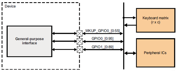
The DIO driver provides an interface to the external connections. The top level diagram of DIO module is as show below. (n= varies for each SOC)

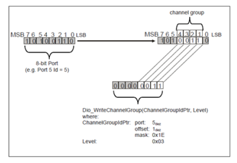
A DIO channel represents a single general-purpose digital input/output pin. A DIO Port is a grouping of several DIO channels by hardware (typically controlled by one hardware register). A DIO Channel Group consists of several adjoining DIO channels represented by a logical group. A DIO channel group belongs to one DIO port as illustrated below
The allocation of DIO instances is dependent on the variant of the device being used. Please refer Device Specific TRM for details.

In general, channels/pins can be configured as input or output. Each DIO instance supports 9 banks of 16 DIO pins each. There are in total 3 instances, one in wakeup domain and two in the main domain.
The DIO peripheral provides the main functionality of input and output. Each pin can be configured independently as input or output with the help of the GPIO direction registers

The main services implemented for the input/output pins are the read and write services for channels, ports and channel groups. The following sequence diagrams elaborate the sequence followed for a typical read and write service

Not Applicable
| Design ID | DES_DIO_015, DES_DIO_016 |
| Requirements Covered | MCAL-1938, MCAL-1939 |
This DIO design is based on the requirements specification for AUTOSAR versioned 4.2.1 and sections below highlight some of the critical changes that would be required between these two versions.
Note that this design doesn’t comprehend or account for other versions of AUTOSAR.
The following have been removed in v4.3.1 specification:
The v4.3.1 specification has added the following sections:
The below diagram shows the overall files structure for the DIO driver. The Dio.c and Dio.h are the 2 files that contain the DIO driver's APIs.

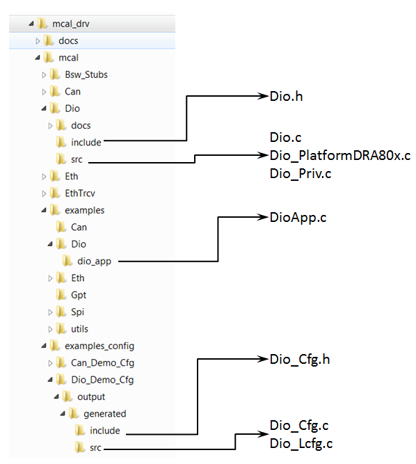
Driver Implemented by
Example Application
| Design ID | DES_DIO_002 |
| Requirements Covered | MCAL-1090, MCAL-1091, MCAL-1092 |
The AUTOSAR DIO Driver Specification details mandatory parameters that shall be configurable via the configurator.Please refer section 10 1
| Design ID | DES_DIO_013 |
| Requirements Covered | MCAL-1074, MCAL-1075, MCAL-1077, MCAL-1078, MCAL-1079, MCAL-1080, MCAL-1081, MCAL-1082, MCAL-1083, MCAL-1084, MCAL-1085, MCAL-1086, MCAL-1076, MCAL-1129, MCAL-1133, MCAL-1136, MCAL-1101, MCAL-1102, MCAL-4170 |
The design's specific configurable parameters are as follows:
| Parameter | Usage comment |
|---|---|
| DioRegisterReadbackApi | This shall allow integrators to specify if the read back of critical registers using the API is required or not. |
| DioDeviceVariant | This shall allow integrators to select the device variant for which integration is being performed.This parameter shall be used by driver to impose device specific constraints. The user guide shall detail the device specific constraints. |
The driver shall support both VARIANT-LINK-TIME & VARIANT-PRE-COMPILE
| Design ID | DES_DIO_013 |
| Requirements Covered | MCAL-1173 |
Errors are classified in two categories, development error and runtime / production error.
| Design ID | DES_DIO_003 |
| Requirements Covered | MCAL-1121, MCAL-1122, MCAL-1123, MCAL-4171, MCAL-4172, MCAL-4173, MCAL-4174 MCAL-4174, MCAL-4173, MCAL-4172, MCAL-4171 |
The detection of development errors is configurable (ON / OFF) at pre-compile time. The switch DioDevErrorDetect will activate or deactivate the detection of all development errors.
| Type of Error | Related Error code | Value (Hex) |
| Invalid channel name requested | DIO_E_PARAM_INVALID_CHANNEL_ID | 0x0A |
| Parameter is NULL Pointer | DIO_E_PARAM_CONFIG | 0x10 |
| Invalid Port Nam3 | DIO_E_PARAM_INVALID_PORT_ID | 0x14 |
| API parameter checking: invalid channel | DIO_E_PARAM_INVALID_GROUP | 0x1F |
| NULL Pointer | DIO_E_PARAM_POINTER | 0x20 |
All detected development errors are reported to Det_ReportError service of the Development Error Tracer (DET).
The detailed API and interface description is available as part of 1 & 4. This section describes the API supported by the MCAL driver and the requirements covered by each of the API.
| Design ID | DES_DIO_004 |
| Requirements Covered | MCAL-1125, MCAL-1126, MCAL-1127, MCAL-1173, MCAL-1130, MCAL-1131, MCAL-1132, MCAL-1139, MCAL-1137, MCAL-1099, MCAL-1134, MCAL-1135 |
The sections below lists some of key data structures that shall be implemented and used in driver implementation
| Type | Identifier | Comments |
|---|---|---|
| uint8 | DIO_HW_UNIT_CNT | Defines the maximum number of Instaces of DIO driver that are configured. |
Type definition used to specify the numeric id of the channel, please refer section 8.2.1 of 1
Type definition used to specify the numeric id of the port, please refer section 8.2.2 of 1
Type definition used to specify the channel group, please refer section 8.2.3 of 1
Used to specify the possible levels of a channel, , please refer section 8.2.4 of 1
Used to specify the possible levels of a port, , please refer section 8.2.5 of 1
Used to specify the direction of a channel.
For the standard APIs please refer 8.3 of 1. Sections below highlight other design considerations for the implementation.
Refer section 8.3.1 of 1
| Design ID | DES_DIO_005 |
| Requirements Covered | MCAL-1143, MCAL-1114, MCAL-1121, MCAL-1096, MCAL-1113, MCAL-1115, MCAL-1119, MCAL-1144, MCAL-1138, MCAL-1093, MCAL-1095, MCAL-1119, MCAL-1094, MCAL-1101 |
Refer section 8.3.2 of 1
| Design ID | DES_DIO_006 |
| Requirements Covered | MCAL-1145, MCAL-1121, MCAL-1108, MCAL-1094, MCAL-1100, MCAL-1096, MCAL-1105, MCAL-1106, MCAL-1146, MCAL-1147, MCAL-1148, MCAL-1094, MCAL-1124, MCAL-1172, MCAL-1107, MCAL-1109, MCAL-1110, MCAL-1093, MCAL-1095, MCAL-1101 |
Refer 8.3.3 of 1
| Design ID | DES_DIO_007 |
| Requirements Covered | MCAL-1149, MCAL-1114, MCAL-1150, MCAL-1122, MCAL-1150, MCAL-1116, MCAL-1151, MCAL-1125 |
Refer section 8.3.4 of 1
| Design ID | DES_DIO_008 |
| Requirements Covered | MCAL-1152, MCAL-1122, MCAL-1108, MCAL-1153, MCAL-1154, MCAL-1155, MCAL-1156 |
Refer section 8.3.5 of 1
| Design ID | DES_DIO_009 |
| Requirements Covered | MCAL-1157, MCAL-1114, MCAL-1123, MCAL-1117, MCAL-1150, MCAL-1158, MCAL-1159, MCAL-1160, MCAL-1094, MCAL-1100, MCAL-1111, MCAL-1154, MCAL-1156, MCAL-1163, MCAL-1140, MCAL-1124, MCAL-1172, MCAL-1099, MCAL-1119, MCAL-1101 |
Refer section 8.3.6 of 1
| Design ID | DES_DIO_010 |
| Requirements Covered | MCAL-1161, MCAL-1123, MCAL-1108, MCAL-1094, MCAL-1100, MCAL-1162, MCAL-1165, MCAL-1112, MCAL-1164, MCAL-1094, MCAL-1100, MCAL-1163, MCAL-1099, MCAL-1101 |
Refer section 8.3.8 of 1
| Design ID | DES_DIO_011 |
| Requirements Covered | MCAL-1168, MCAL-1108, MCAL-1169, MCAL-1096, MCAL-1113, MCAL-1115, MCAL-1119, MCAL-1144, MCAL-1170, MCAL-1171, MCAL-1094, MCAL-1101 |
Refer section 8.3.7 of 1
| Design ID | DES_DIO_012 |
| Requirements Covered | MCAL-1166, MCAL-1124, MCAL-1167 |
As noted from previous implementation, some of the critical configuration registers could potentially be corrupted by other entities (s/w or h/w). One of the recommended detection methods would be to periodically read-back the configuration and confirm configuration is consistent. The service API defined below shall be implemented to enable this detection
| Description | Comments | |
| Service Name | Dio_RegisterReadback | Can potentially be turned OFF (NON Standard configurable parameters) |
| Syntax | uint32 Dio_RegisterReadback (DIO_ChannelType ChannelId) | Returns PID register of associated DIO module |
| Service ID | NA | |
| Sync / Async | Sync | |
| Reentrancy | Non Reentrant | |
| Parameter in | ChannelId | Channel Identifier |
| Parameters out | None | |
| Return Value | Standard unsigned integer | An integer value |
This design expects that implementation will require to use following global variables.
| Variable | Type | Description | Default Value |
|---|---|---|---|
| Dio_ConfigValidChannelMask | uint32 array | Auto generated array of enabled ports | NA |
Sections below list some of the important design decisions and rational behind those decision.
There are different numbers of pins in different SOCs as well as different instances available in domains such as wakeup and main domain. The Driver can also be hosted on different cores. Multiple approaches are available to support to support this and following are top 2 options.
Should be scalable (minimal changes to change reserved pins map) and easy to maintain.
Chosen to use "One Project and conditional generation of configuration" as it scalable and minimizes generation of wrong configuration.
AUTOSAR specification dosen't explicitly specify the width of the PORT, its dependent on the underlying hardware. As per the hardware specification each port is 16 bits wide. However, 2 ports are represented by a single 32 bit register in the hardware. This would require special handling, especially when the ASYNC APIs have to supported.
Low complexity implementation and scalable
Chosen to use "32 bits per port" it minimizes generation use of exclusive areas
The sections below identify some of the aspects of design that would require emphasis during testing of this design implementation
| Revision | Date | Author | Description | Status |
|---|---|---|---|---|
| 0.1 | 25 July 2018 | Vibha Pant | First version | Approved |
| 0.2 | 09 Oct 2018 | Sujith S | Format change and re-order | Approved |
| 0.3 | 09 Oct 2018 | Vibha Pant | Review Comments Addressed | Approved |
| 0.4 | 28 Jan 2019 | Vibha Pant | Section for Autosar V2.3.1 | Approved |
| 0.5 | 19 Jan 2020 | Sunil M S | Updates w.r.o porting AUTOSAR 4.3.1 Version | Approved |
 1.8.15