4.7. IPC
4.7.1. Introduction
TI Jacinto7/AM65XX family of devices consists of many cores - ARM53/72, R5Fs (MCU or Main Domain) and/or DSPs (C66x / C7x). The actual cores vary with actual device. Refer to the datasheet of the device for the actual cores present on SoC. Inter-Processor Communication (IPC) provides a communication channel between various cores. IPCLLD is the low-level driver for IPC, which provides a core-agnostic and OS-agnostic framework for communication.
More information regarding the TI multicore processors is available .
4.7.2. Terms and Abbreviation
| Term | Definition or Explanation |
|---|---|
| IPC | Inter-Processor Communication |
| RirtIO | Virtual I/O driver |
| MailBox | IP which provides queued interrupt mechanism for communication channel |
| VRing | Ring Buffer in shared memory |
| PDK | Platform Development Kit |
| PSDKRA | Processor SDK RTOS Automotive |
| PSDKLA | Processor SDK Linux Automotive |
4.7.3. References
- Sitara Processor Datasheet
- For J721e datasheet, please contact TI presentative
4.7.4. Features
- Provides ipc low-level driver, which can be compiled for any of the cores on AM65xx or J721E devices
- Supports Bios/Bios communication and Linux/Bios concurrently for all cores
- Supports TI RTOS, Linux, QNX and baremetal (No-OS) use.
- It can be extended for any third-party RTOS by adding OS adaptation layer
- IPCLLD also provides many examples for quick reference
4.7.5. Installation
IPCLLD is part of TI PDK (Platform Development Kit) package. Once PRSDK is installed, PDK and all dependent packages and tool-chains are installed automatically. IPCLLD can also be located at <PRSDK_HOME>/pdk/packages/ti/drv/ipc. IPCLLD is also available publically at https://git.ti.com/processor-sdk/pdk/ at packages/ti/drv/ipc.
It can also be cloned using following git command:
- git clone git://git.ti.com/processor-sdk/pdk.git
- Provides many examples for quick reference
The file and directory oraganization are as below.
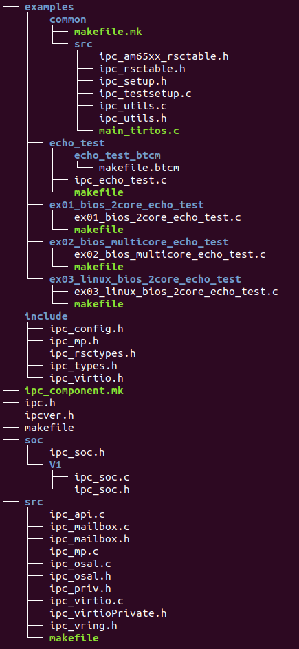
4.7.6. Build
IPCLLD uses the PDK build systems to build the IPCLLD library and example applications.
4.7.6.1. Dependency of External PDK Components
IPCLLD does not access any hardware diretly. It uses the PDK/csl component to configure Mailbox registers. It uses sciclient to set/release Mailbox interrupt. Also it uses PDK/osal to configure OS-related steps like Semaphore etc.
- pdk/csl : Configures Mailbox registers
- pdk/sciclient : Set Mailbox interrupts
- pdk/osal : To register for HWI and other kernel stuffs.
4.7.6.2. Command to build IPCLLD
The build can be done either from the IPCLLD’s path in the PDK packages, or from the PDK build folder. For either method, the following environment variables must be defined, or supplied with the build command (if they are different from the defaults of the SDK installation):
- SDK_INSTALL_PATH: Installation root for sdk
- TOOLS_INSTALL_PATH: where all the tool chains are installed, if different from SDK_INSTALL_PATH
- PDK_INSTALL_PATH: Installtion root for pdk
The following build instructions are for Linux. For Windows build, please replace “make” with “gmake”.
Method 1:
These libraries and examples are built from the IPCLLD’s path in the PDK packages:
PDK_INSTALL_DIR/packages/ti/drv/ipc
| Target | Build Command | Description |
|---|---|---|
| lib | make PDK_INSTALL_PATH=PDK_INSTALL_DIR/packages SDK_INSTALL_PATH=SDK_INSTALL_PATH lib | IPCLLD library |
| apps | make PDK_INSTALL_PATH=PDK_INSTALL_DIR/packages SDK_INSTALL_PATH=SDK_INSTALL_PATH apps | IPCLLD examples |
| clean | make PDK_INSTALL_PATH=PDK_INSTALL_DIR/packages SDK_INSTALL_PATH=SDK_INSTALL_PATH clean | Clean IPCLLD library and examples |
| all | make PDK_INSTALL_PATH=PDK_INSTALL_DIR/packages SDK_INSTALL_PATH=SDK_INSTALL_PATH all | Build IPCLLD library and examples |
Method 2:
If building from the PDK build folder, then use following steps to build
Go to PDK_INSTALL_DIR/packages/ti/build
| Target | Build Command | Description |
|---|---|---|
| lib | make -s -j BUILD_PROFILE=<debug/release> BOARD=<am65xx_evm/j721e_evm> CORE=<core_name> ipc | IPCLLD library |
| example | make -s -j BUILD_PROFILE=<debug/release> BOARD=<am65xx_evm/j721e_evm> CORE=<core_name> ipc_echo_test | ipc_echo_test example (this can be replaced with any available IPC test name to build the specific test) |
| clean | make -s -j BUILD_PROFILE=<debug/release> BOARD=<am65xx_evm/j721e_evm> CORE=<core_name> ipc_echo_test_clean | Clean the ipc_echo_test (this can be replaced with any available IPC test name to build the specific test) |
See Example Details for list of supported examples.
4.7.6.3. Available Core names
- AM65XX:
- mpu1_0 (A53)
- mcu1_0 (r5f0_0)
- mcu1_1 (r5f0_1)
- J721E:
- mpu1_0 (A72)
- mcu1_0 (mcu-r5f0_0)
- mcu1_1 (mcu-r5f0_1)
- mcu2_0 (main-r5f0_0)
- mcu2_1 (main-r5f0_1)
- mcu3_0 (main-r5f1_0)
- mcu3_1 (main-r5f1_1)
- c66xdsp_1 (c66x_0)
- c66xdsp_2 (c66x_1)
- c7x_1 (c71x_0)
4.7.6.4. Expected Output
The built example binaries can be found in the PDK’s binary folder:
PDK_INSTALL_PATH/packages/ti/binary/<test_name>/bin/<board_name>/
4.7.7. Running the IPCLLD examples
IPCLLD comes with the following examples.
4.7.7.1. Example Details
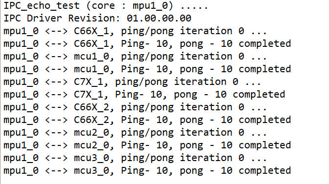
- ipc_echo_test: This is most generic example application where mpu1_0 is running Linux, and all other cores running bios. All cores talk to each other bi-diectionally. It is send ping message and remote end responds pong message. There are 10000 ping/pong messages exchanged between each core-pair.
- ex01_bios_2core_echo_test: This is the simplistic ping/pong application between any two cores running BIOS
- ex02_bios_multicore_echo_test: All cores running BIOS, many-to-many communication, each sending ping/pong with each other. mpu1_0 is also running BIOS.
- ex03_linux_bios_2core_echo_test: This is simplistic ping/pong application where mpu1_0 running Linux and any other core is running Bios.
- ex04_linux_baremetal_2core_echo_test: AM65xx only. This is a ping/pong application where mpu1_0 is running Linux and the other core is baremetal (no OS).
4.7.7.2. Loading Remote Firmware
Remote firmware can be loading using CCS or using uBoot SPL.
Loading using CCS :
Sciclient module contains default system firmware and CCS script to load the system firmware. The load scripts should be modified to reflect the correct full-path of the script location. Once the script is updated,
start TI CCS 9.1 or newer
open CCS script console using menu View –> Scripting Console
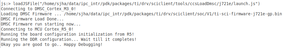
- Run the script using following command (example below is for J721E, use the appropriate one for your target)
- loadJSFile(“PDK_INSTALL_DIR/packages/ti/drv/sciclient/tools/ccsLoadDmsc/j721e/launch.js”)
- Connect the cores
- select the core
- right-click and connect
- Load the remote binaries
- Menu Run –> Load Program
Run the cores.
After running the cores, the sample output should look something like below.
Loading using SPL/uBoot
Run following steps to configure remote firmware for SPL loading with HLOS running on MPU
- Copy the remote firmware to rootfs at /lib/firmware/pdk-ipc folder
- cd /lib/firmware
- Remove old soft link for remote cores
- rm j7*
- Create new soft links
- ln -s /lib/firmware/pdk-ipc/ipc_echo_test_c66xdsp_1_release.xe66 j7-c66_0-fw
- ln -s /lib/firmware/pdk-ipc/ipc_echo_test_c66xdsp_2_release.xe66 j7-c66_1-fw
- ln -s /lib/firmware/pdk-ipc/ipc_echo_test_c7x_1_release.xe71 j7-c71_0-fw
- ln -s /lib/firmware/pdk-ipc/ipc_echo_test_mcu2_0_release.xer5f j7-main-r5f0_0-fw
- ln -s /lib/firmware/pdk-ipc/ipc_echo_test_mcu2_1_release.xer5f j7-main-r5f0_1-fw
- ln -s /lib/firmware/pdk-ipc/ipc_echo_test_mcu3_0_release.xer5f j7-main-r5f1_0-fw
- ln -s /lib/firmware/pdk-ipc/ipc_echo_test_mcu3_1_release.xer5f j7-main-r5f1_1-fw
- ln -s /lib/firmware/pdk-ipc/ipc_echo_testb_mcu1_0_release.xer5f j7-mcu-r5f0_0-fw
- ln -s /lib/firmware/pdk-ipc/ipc_echo_test_mcu1_1_release.xer5f j7-mcu-r5f0_1-fw
- sync : write the changes to filesystem
- Reboot the system
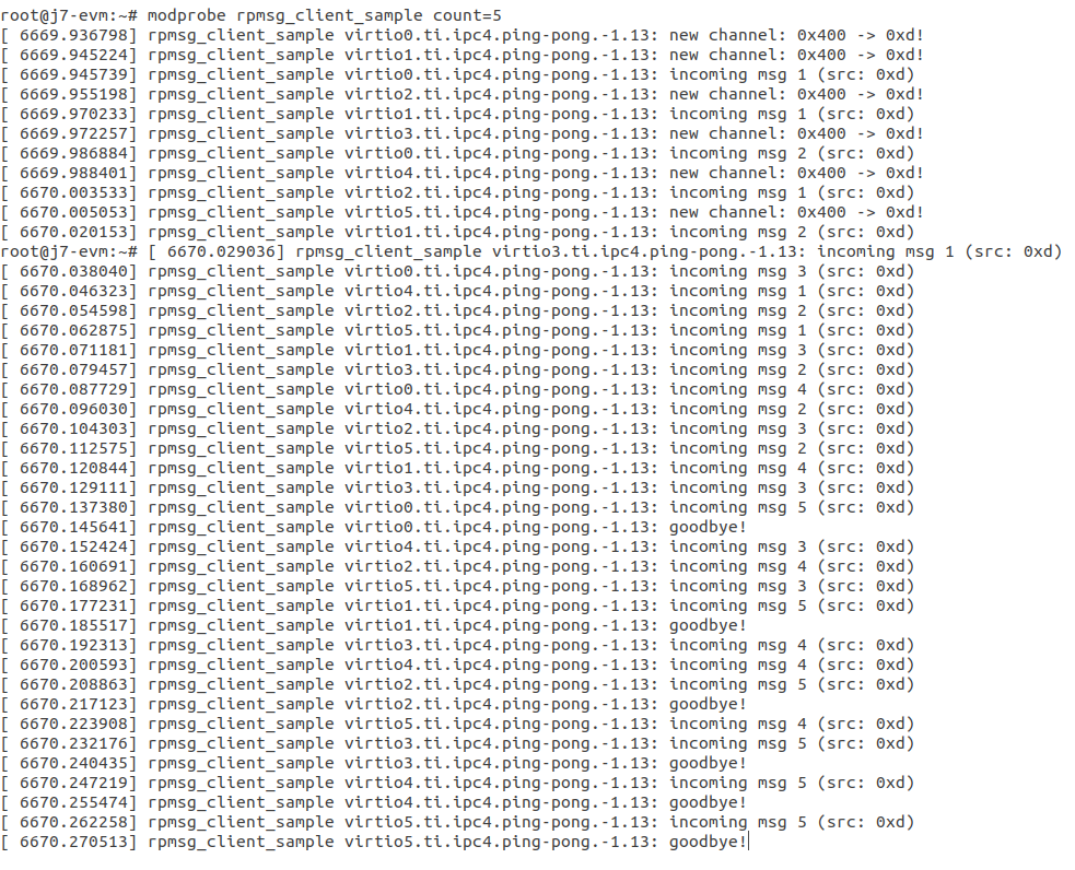
4.7.7.3. Running the Echo Tests
In this section ipc_echo_test is used to demonstrate, but same instructions apply to other examples that have Linux on MPU, though test output may be slightly different.
Login as root
Start sample app as below
- modprobe rpmsg_client_sample count=5
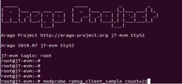
- After running the sample app, it should display something below
4.7.8. IPCLLD Design Details
- Ring Buffer is used as shared memory to transfer the data. It must be reserved system wide. The base-address and size of ring Buffer must be provided to IPCLLD. It must be same for all core applications. The invidual memory-range for Ring Buffer between core combinations are calculated internally inside the library. The default base-address and size used in the IPC examples is
| Device | Base Address | Size |
|---|---|---|
| J721E | 0xAA000000 | 0x1C00000 |
| AM65XX | 0xA2000000 | 0x200000 |
The VRing base address and size is passed from the application during the Ipc_initVirtIO() call. See Writing HelloWorld App using IPCLLD for the example of usage.
Additionally the Ring Buffer memory used when communicating with MPU running Linux must be reserved system wide. The base-address and size of the ring buffer is different from what is used between cores not running Linux. The base-address and size of the ring Buffer is provided to IPCLLD when Linux updates the core’s resource table with the allocated addresses. Linux allocates the base-address from the first memory-region. See Resource Table for more information.
- For each RPmessage object, the memory must be provided to library from local heap. All subsequent send/recv API is using rpmessage buffer provided during the create function.
- RPMessage can transfer maximum of 512 bytes of data. For larger data transfers, it is recommended to pass a pointer/handle/offset to a larger shared memory buffer inside the message data.
- For firmware that will communicate with Linux over IPC, a Resource Table is required. See Resource Table for more information.
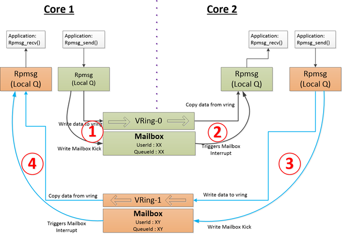
4.7.8.1. Typical Data-Flow in IPCLLD communication between two cores
Following picture illustrates the data flow between two cores using mailbox IP as transport.
4.7.8.2. Resource Table
For applications that will use Linux IPC, a resource table is required. Example resource tables can be found in the IPC examples:
| Device | Resource Table Example Location |
|---|---|
| J721E | examples/common/src/ipc_rsctable.h |
| AM65XX | examples/common/src/ipc_am65xx_rsctable.h |
The resource table must have at least one entry, the VDEV entry, to define the the vrings used for IPC communication with Linux. Optionally, the resource table can also have a TRACE entry which defines the location of the remote core trace buffer.
The VDEV entry specifies the address as RPMSG_VRING_ADDR_ANY, meaning that the address will be allocated by the Linux driver during loading. The allocation is made from the first memory-region specified in the dts file for the remote core. For example, if the dts entry for mcu_r5fss0_core0 is
reserved_memory: reserved-memory {
    #address-cells = <2>;
    #size-cells = <2>;
    ranges;

    mcu_r5fss0_core0_dma_memory_region: r5f-dma-memory@a0000000 {
            compatible = "shared-dma-pool";
            reg = <0 0xa0000000 0 0x100000>;
            no-map;
    };

    mcu_r5fss0_core0_memory_region: r5f-memory@a0100000 {
            compatible = "shared-dma-pool";
            reg = <0 0xa0100000 0 0xf00000>;
            no-map;
    };
}
then the allocation for the vrings will come from the 0xa0000000 entry.
4.7.8.3. Memory Considerations
As mentioned in IPCLLD Design Details, the Ring Buffer memory must be reserved system-wide. In addition, the Ring Buffer memory should be configured as non-cached on all cores using IPCLLD. For examples of configurations for Ring Buffer memory, refer to the examples in pdk/packages/ti/drv/ipc/examples/.
4.7.9. Writing HelloWorld App using IPCLLD
Step1: Initialize MultiProc with SelfId, and how many remote cores
Ipc_mpSetConfig(selfProcId, numProc, remoteProc);
Step2: Load the Resource Table (required only if running Linux on A72/A53)
Ipc_loadResourceTable((void*)&ti_ipc_remoteproc_ResourceTable);
See Resource Table for details on the resource table.
Step3: Initialize VirtIO (note: Base Address for Shared Memory used for RingBuffer)
vqParam.vqObjBaseAddr = (void*)sysVqBuf;
vqParam.vqBufSize     = numProc * Ipc_getVqObjMemoryRequiredPerCore();
vqParam.vringBaseAddr = (void*)VRING_BASE_ADDRESS;
vqParam.vringBufSize  = VRING_BUFFER_SIZE;
Ipc_initVirtIO(&vqParam);
Step4: Initialize RPMessage
RPMessage_init(&cntrlParam);
Step5: Send Message
RPMessage_send(handle, dstProc, ENDPT1, myEndPt, (Ptr)buf, len);
Step6: Receive Message
RPMessage_recv(handle, (Ptr)buf, &len, &remoteEndPt, &remoteProcId, timeout);