7. EVM Setup for J784S4
This section is intended to give a quick reference of EVM related to SDK usage. Full EVM documentation will be referenced at TDA4AP, TDA4VP, TDA4AH, TDA4VH EVM at a later time.
Important
The power supply requires an output voltage of 24-48 VDC, and output capacity of 100-160W, depending on use case and connected peripherals.
When connecting the fusion daughter card, the power cable connecting processor board and fusion board should look exactly like the picture in section Fusion daughter card. (P.S. The same cable from TDA2P EVM has the opposite wire connection at one end)
7.1. EVM Setup to run SDK demos
7.1.1. Daughter card requirements
Below table shows the daughter cards required for various features/demos
Feature |
Fusion 1 card |
IMX390+UB953 FPDLink sensors |
QPENet card |
|---|---|---|---|
eDP (DisplayPort) display (1) |
na |
na |
na |
HDMI display (2) |
na |
na |
na |
CSI2RX camera input |
REQURIED |
REQURIED |
na |
CPSW9G (ETHFW) demos |
na |
na |
REQUIRED |
CAN demos (1) |
na |
na |
na |
7.1.2. UART terminal setup
Connect USB cable to Main UART port on EVM (see EVM)
4 UART ports would be visible at the PC side
Port 0 from this is used this for Linux, RTOS UART terminal from A72
Setup UART for 115200 baud rate, 8 data bits, no party, 1 stop bit
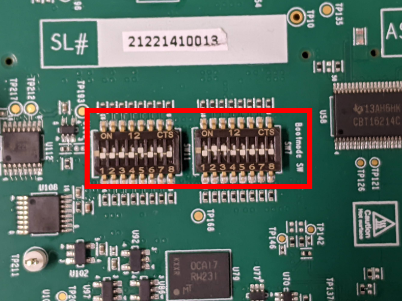
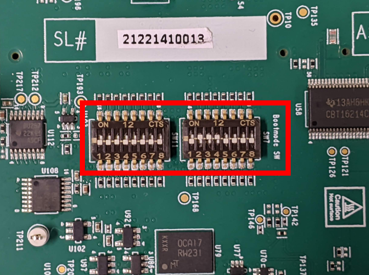
7.1.3. Boot Modes
Bootmodes are selected using the SW11 and SW7 switches on the EVM.
7.1.3.1. No Boot Mode
When you want the binaries to be loaded from a debugger (CCS), the EVM has to be set in the NO boot mode.
Following are the switch settings to do the same.:
SW11[1-8] = 1000 1000
SW7[1-8]  = 0111 0000
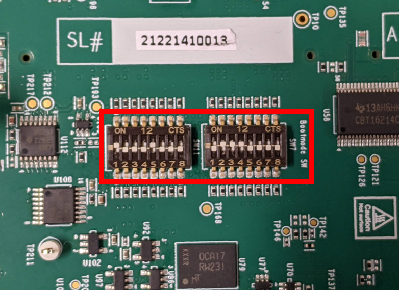
Fig. 7.1 No Boot Mode
7.1.3.2. SD Boot Mode
Following are the switch settings to set the boot mode to SD for EVM.:
SW11[1-8] = 1000 0010
SW7[1-8]  = 0000 0000
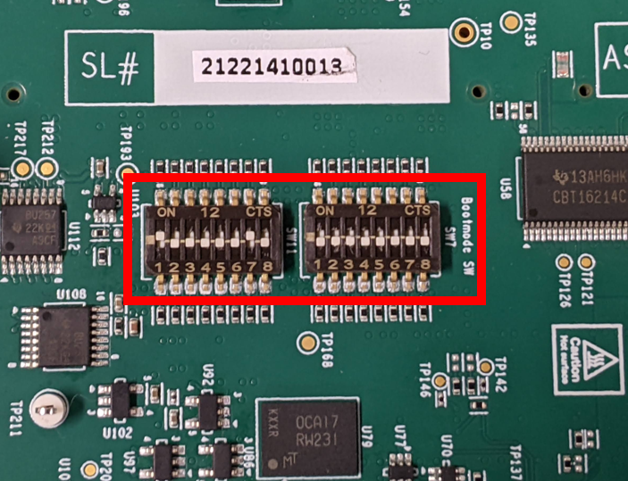
Fig. 7.2 MMC/SD Boot Mode
7.2. EVM and Daughter Card information
7.2.1. EVM
Whereas other J7 family boards consist of a Common Processor Board plus SOM, the J784S4 Evaluation Module (EVM) has these two components combined into a single board. The J784S4 EVM is the main board which includes the following:
J784S4 SoC
Leo PMIC (Power controller)
32 (4x8) GiB LPDDR4 RAM
XSPI NOR flash
In addition, the J784S4 EVM has peripherals to provide most common functionality. It has expander ports to connect to different adapter cards.
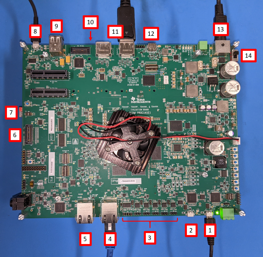
Fig. 7.7 J784S4 EVM
Contents of the board
4xUART to USB port for Main uarts
Port0 from this is used this for Linux, RTOS UART terminal from A72
2xUART to USB port MCU domain uarts
Port0 from this is used for Cortex M4F UART
Port1 from this is used for MCU R5F UART
6x CAN FD Interfaces
Main Domain Ethernet (CPSW2G) port
MCU Domain Ethernet (CPSW2G) port
MIPI JTAG connector
SD card slot
XDS110 on board USB JTAG connector
USB Host ports
Quad Port Ethernet daughter card (bottom of EVM) sold separately
2x Display (eDP/DP) ports
Display0 is used by software for eDP/DP output
USBC port
12V Power input
Power switch
7.2.2. Quad Port Ethernet daughter card
Quad Port Ethernet (QPENet) board is an adapter board which offers additional CPSW9G Ethernet port capabilities to the Jacinto7 EVM. It is connected to the bottom of the EVM beneath the 2x Display (eDP/DP) ports.
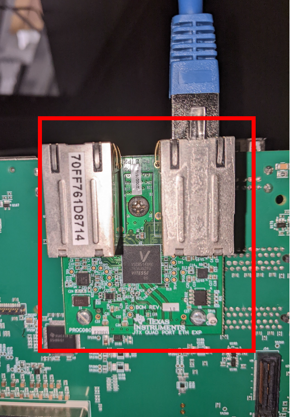
Fig. 7.8 QPENet daughter card
7.2.3. Fusion daughter card
Fusion daughter card is adapter board to connect 8 camera sensors (IMX390+UB953 serializer) through de-serializer (UB960) available on the Fusion1 daughter card to CSI2RX ports of J784S4 SoC.
Connect the daughter card to bottom side of EVM at connector J57.
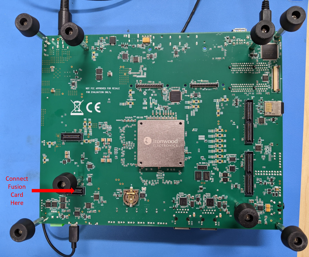
Fig. 7.9 CSI2 Exp Connector
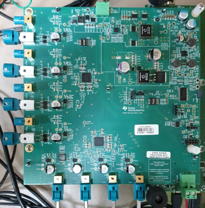
Fig. 7.10 Fusion1 Board
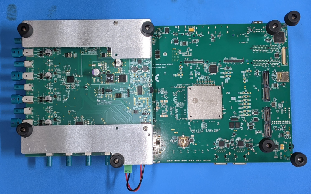
Fig. 7.11 Fusion1 Mounting