7.5. How the Linker Handles Sections
The linker has two main functions related to sections. First, the linker uses the sections in object files as building blocks; it combines input sections to create output sections in an executable output module. Second, the linker chooses memory addresses for the output sections; this is called placement. Two linker directives support these functions:
The MEMORY directive allows you to define the memory map of a target system. You can name portions of memory and specify their starting addresses and their lengths.
The SECTIONS directive tells the linker how to combine input sections into output sections and where to place these output sections in memory.
Subsections let you manipulate the placement of sections with greater precision. You can specify the location of each subsection with the linker’s SECTIONS directive. If you do not specify a subsection, the subsection is combined with the other sections with the same base section name. See SECTIONS Directive Syntax.
It is not always necessary to use linker directives. If you do not use them, the linker uses the target processor’s default placement algorithm described in Default Placement Algorithm. When you do use linker directives, you must specify them in a linker command file.
Refer to the following sections for more information about linker command files and linker directives:
7.5.1. Combining Input Sections
The following figure provides a simplified example of the process of linking two files together. Since this is a simplified example, it does not show all the sections that will be created or the actual sequence of the sections. See Default Placement Algorithm for the actual default memory placement map for Arm.
Figure: Combining Input Sections to Form an Executable Object Module
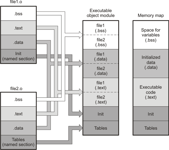
In the above figure, file1.o and file2.o have been assembled to be used as linker input. Each contains the .text, .data, and .bss default sections; in addition, each contains a user-named section. The executable object module shows the combined sections. The linker combines the .text section from file1.o and the .text section from file2.o to form one .text section, then combines the two .data sections and the two .bss sections, and finally places the user-named sections at the end. The memory map shows the combined sections to be placed into memory.
7.5.2. Placing Sections
The previous figure illustrates the linker’s default method for combining sections. Sometimes you may not want to use the default setup. For example, you may not want all of the .text sections to be combined into a single .text section. Or you may want a user-named section placed where the .data section would normally be allocated. Most memory maps contain various types of memory (RAM, ROM, EEPROM, FLASH, etc.) in varying amounts; you may want to place a section in a specific type of memory.
For further explanation of section placement within the memory map, see the discussions in The MEMORY Directive and The SECTIONS Directive. See Default Placement Algorithm for the actual default memory allocation map for Arm.