5.1. Software Pipelining
This chapter introduces the concept of software pipelining, which is a compiler optimization that is essential for achieving high-performance on a VLIW architecture like the C7000 DSP.
5.1.1. Software Pipelining Motivation
As described in C7000 Digital Signal Processor CPU Architecture, the C7000 DSP has a very-long instruction word (VLIW) architecture that contains 13 fully-pipelined functional units on which instructions can execute. Up to 13 instructions can start on any cycle. Keeping these functional units busy executing instructions is key to achieving performance on the C7000 DSP core.
Keeping all of these functional units busy can be challenging. Software pipelining is a technique used on inner loops by a compiler to attempt to keep the functional units as busy as possible. The C7000 compiler performs software pipelining automatically on inner loops, when appropriate compiler options are used.
Without software pipelining, inner loops will likely suffer from poor performance on a VLIW architecture. This is because without software pipelining, only a single iteration of the loop is executed at a time.
Figure 5.1 shows a conceptual representation of an inner loop that is not software pipelined. The loop in this example has five equal sized sections, A through E. The arrow represents repeated execution of the loop body (via a conditional branch instruction at the end of section E).

Figure 5.1 Inner Loop, Not Pipelined
Figure 5.2 shows that same loop's execution over time of three iterations. The y-axis represents time and the x-axis visualizes which iteration of the loop is being executed. The sections of the loop are executed sequentially, from top to bottom, and then jumps to the top of the loop body after the last part of the loop is completed. If n is the number of iterations the loop is to perform, the loop jumps back to the top n-1 times.

Figure 5.2 Inner Loop, Not Pipelined, 3 Iterations
In a normal loop, there are typically few instructions that can be executed in parallel. This is partly because of dependencies within the loop body from one instruction to the next, as one instruction in the loop is calculating a result that is likely consumed by a subsequent instruction in the loop. This can lead to resource under-utilization. In other words, during the execution of this loop, only one or two of the functional units would be used at any given time, and this would lead to many of the functional units being unused.
5.1.2. Software Pipelining Overview and Terminology
Software pipelining is a technique the compiler uses to overlap successive iterations of a loop in order to more fully utilize the multiple functional units on the CPU. In this manner, the loop executes much faster than a sequentially executed loop.
Figure 5.3 shows the execution of this same example loop after software pipelining has been performed. We can see that rather than waiting for an entire iteration of the loop to complete before starting the next iteration, in this example the 2nd iteration starts only after the 1st iteration's section A is complete. In other words, the 2nd iteration starts after only some of 1st iteration is complete. As long as correctness can be preserved, iteration i+1 can start before iteration i finishes. This generally permits a much higher utilization of the machine's resources than might be achieved from other scheduling techniques.
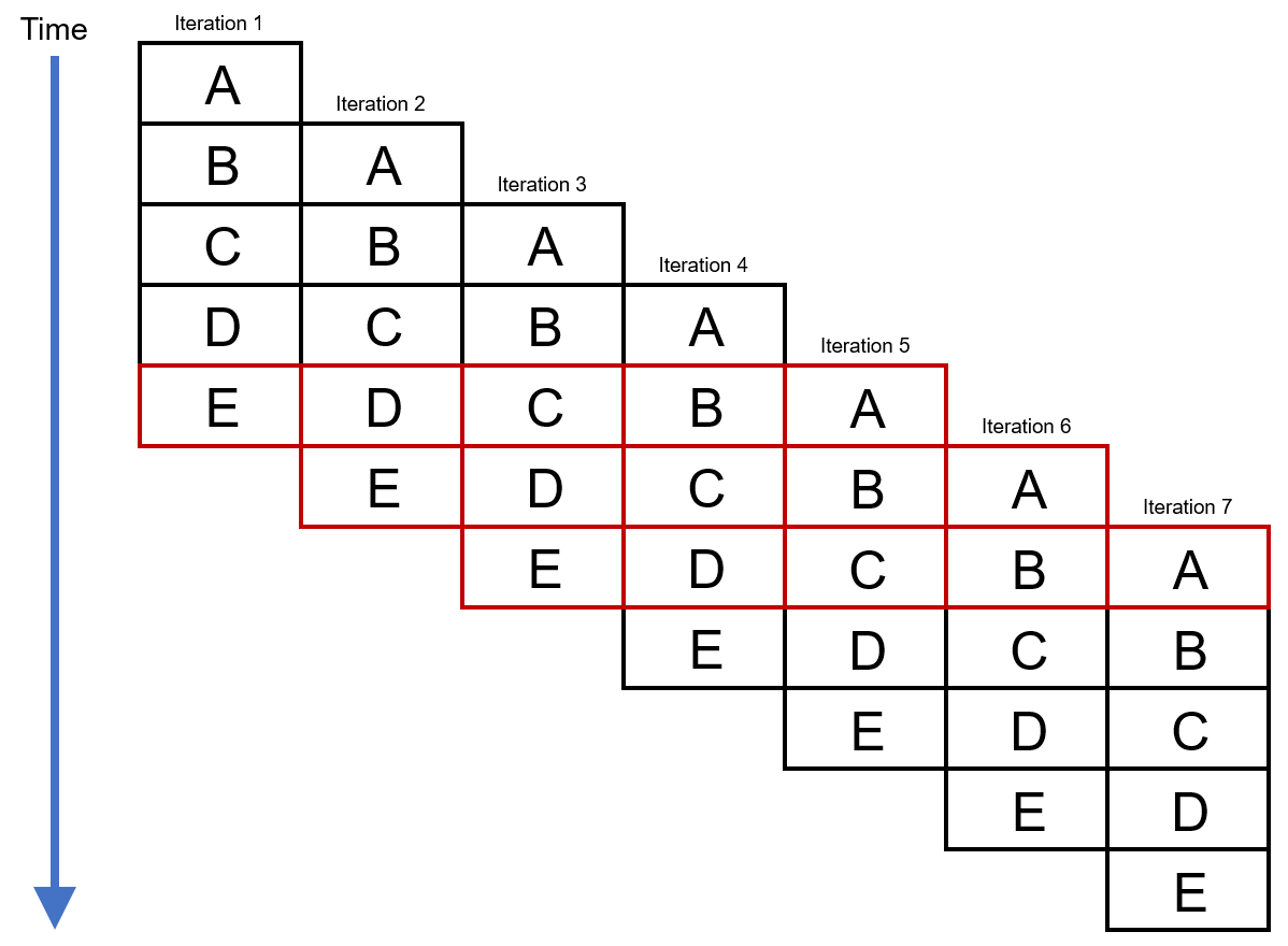
Figure 5.3 Inner Loop, Pipelined, 7 Iterations
Notice in Figure 5.3 that much more work is being performed per unit time in this example. Also note there is a repeating pattern (in the color red) once iteration 5 has started. This pattern continues until iteration 7. This pattern involves each section (A through E) of the loop body being executed at the same time (but from different iterations!). Software pipelining takes advantage of this pattern -- the compiler creates a kernel that repeats as often as it necessary to execute the proper number of iterations of the loop. The compiler also creates sections called the prolog and the epilog to start ("pipe-up") and finish ("pipe-down") the software pipeline execution.
5.1.2.1. Prolog, Kernel, and Epilog
Figure 5.4 shows a conventional diagram of a software pipelined loop with some of the parts identified.
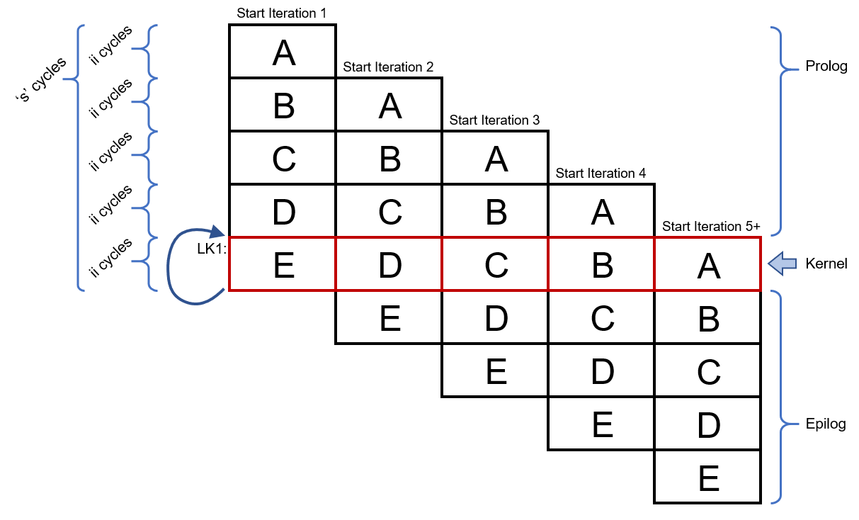
Figure 5.4 Software Pipelined Loop with Components Identified
After software pipelining, the software pipelined loop has three major phases, as shown in Figure 5.4:
pipe-up (prolog) phase during which overlapped iterations are started.
steady-state (kernel), repeating phase during which iterations may start, continue, and/or finish
pipe-down (epilog) phase during which any unfinished iterations are completed
Let's review each phase in more detail.
The prolog portion of the software pipelined loop starts a number of iterations in order to get the software pipelined loop going. The number of iterations that the prolog starts is dependent on how many iterations were overlapped during the software pipelining process by the compiler. The prolog executes once.
The kernel is a repeating portion of the software pipelined loop. The
compiler generates a branch instruction that jumps to the top of the kernel
in order to execute as many repetitions of the kernel as is necessary to
correctly execute all of the user-mandated iterations of the inner loop.
The kernel starts, continues, and finishes iterations, all at the same time.
The kernel in the above figure is colored red. The loop back to the top of
the kernel is depicted by a curved arrow to the top of the kernel and the
assembly label LK1.
After the correct number of iterations of the loop have been started (and some iterations likely have finished by this point), the kernel branch will not be taken and thus execution will fall-through instead of branching to the top of the kernel. Thus, execution will proceed into the epilog portion of the software pipelined loop. This epilog section completes any unfinished loop iterations that were started by the prolog or the kernel. The epilog executes once.
Note that some iterations of the executing software pipelined loop may completely execute (start and finish) within the repeating kernel. Earlier iterations may start in the prolog and finish in the kernel. Later iterations may start in the kernel and finish in the epilog. Loops with small iteration counts may have iterations that start in the prolog, continue in the kernel, and finish in the epilog.
5.1.2.2. Initiation Interval and Single-Scheduled Iteration Length
As shown in Figure 5.4, the number of cycles between starting
two successive iterations of the loop is called the initiation interval,
or ii. In a software-pipelined loop, a new iteration is initiated every
ii cycles. Because the ii has a large effect on a loop's performance, the
compiler tries to schedule a loop at the lowest ii possible. The ii of a
loop (and other information) is printed in a helpful comment section in the
assembly file. See later sections of this document for information on how to
keep the assembly file and generate these assembly comments.
As seen in the figure above, length s is the length of a single
scheduled iteration of the software-pipelined loop. This is the amount
of time it takes for one iteration of the loop to execute when the loop
is software pipelined.
A single iteration of the software pipelined loop (s) may be much more
than ii cycles, but there will be multiple loop iterations executing at
once, all at a different stage of completion.
In an efficient software pipelined loop, ii is usually much less than
the length s.
There are also two other blocks that the compiler adds, one above the prolog block, and one below the epilog block. Often during the process of software pipelining, the compiler needs to add various instructions to facilitate the setup and finalization of a software pipelined loop. These blocks are sometimes able to be merged into surrounding blocks after software pipelining by the compiler, so they may not appear in the final assembly.
The compiler attempts to software pipeline innermost loops. These are loops that do not have any other loops within them. Note that during the compilation process, software pipelining occurs after inlining and after loop transformations that may combine loops. So in certain cases you may see the compiler software pipelining more of your code than you expect.
5.1.3. Software Pipelining: Performance and Code-Size Tradeoff
Typically, software pipelining dramatically improves the performance of an inner loop. However, code size will typically increase as the result of the compiler performing software pipelining.
Software pipelining is not performed by the C7000 compiler when the compiler
option --opt_for_speed=1/-mf1 or --opt_for_speed=0/-mf0 is
used. Therefore, the user is encouraged to use --opt_for_speed=1/-mf1
or --opt_for_speed=0/-mf0 for any files or functions that contain
code where the performance is not important or small code size is desired.
5.1.4. Software Pipelining Example
The following example shows the source code for a simple weighted vector sum.
// weighted_vector_sum.cpp
// Compile with "cl7x -mv7100 --opt_level=3 --debug_software_pipeline
// --src_interlist --symdebug:none weighted_vector_sum.cpp"

void weighted_sum(int * restrict a, int *restrict b, int *restrict out,
int weight_a, int weight_b, int n)
{
    #pragma UNROLL(1)
    #pragma MUST_ITERATE(1024, ,32)
    for (int i = 0; i < n; i++)
    {
        out[i] = a[i] * weight_a + b[i] * weight_b;
    }
}
To simplify this first software-pipelining example, two pragmas are used:
The
UNROLL(1)pragma tells the compiler not to perform vectorization, which is a transformation technique that is demonstrated in the next section.The
MUST_ITERATEpragma conveys information on how many times the loop executes and is explained later in this document. The example uses this pragma to prevent a "duplicate loop" from being generated.
Then we compile this code with the following command:
cl7x --opt_level=3 --debug_software_pipeline --src_interlist --symdebug:none weighted_vector_sum.cpp
The --symdebug:none option prevents the compiler from
generating debug information and the associated debug
directives in the assembly. This debug information is not
relevant to the discussion in this document and if included,
would unnecessarily lengthen the assembly output examples shown here. Normally,
you would not turn off debug generation as the generation of
debug information does not degrade performance.
Because the --src_interlist option is used, the
compiler-generated assembly file is not deleted and has the
following contents:
  1   ;*----------------------------------------------------------------------------*
  2   ;*   SOFTWARE PIPELINE INFORMATION
  3   ;*
  4   ;*      Loop found in file      : weighted_vector_sum.cpp
  5   ;*      Loop source line        : 10
  6   ;*      Loop opening brace source line   : 11
  7   ;*      Loop closing brace source line   : 13
  8   ;*      Known Minimum Iteration Count    : 1024
  9   ;*      Known Max Iteration Count Factor : 32
 10   ;*      Loop Carried Dependency Bound(^) : 0
 11   ;*      Unpartitioned Resource Bound     : 2
 12   ;*      Partitioned Resource Bound       : 2 (pre-sched)
 13   ;*
 14   ;*      Searching for software pipeline schedule at ...
 15   ;*        ii = 2  Schedule found with 7 iterations in parallel
 16   ;*
 17   ;*      Partitioned Resource Bound(*)    : 2 (post-sched)
 18   . . .
 19   ;*----------------------------------------------------------------------------*
 20   ;*        SINGLE SCHEDULED ITERATION
 21   ;*
 22   ;*        ||$C$C36||:
 23   ;*   0              TICK    ; [A_U]
 24   ;*   1              SLDW    .D1     *D1++(4),BM0      ; [A_D1] |12|
 25   ;*     ||           SLDW    .D2     *D2++(4),BM1      ; [A_D2] |12|
 26   ;*   2              NOP     0x5     ; [A_B]
 27   ;*   7              MPYWW   .N2     BM2,BM0,BL0       ; [B_N] |12|
 28   ;*     ||           MPYWW   .M2     BM3,BM1,BL1       ; [B_M2] |12|
 29   ;*   8              NOP     0x3     ; [A_B]
 30   ;*  11              ADDW    .L2     BL1,BL0,B0        ; [B_L2] |12|
 31   ;*  12              STW     .D1X    B0,*D0++(4)       ; [A_D1] |12|
 32   ;*     ||           BNL     .B1     ||$C$C36||        ; [A_B] |10|
 33   ;*  13     ; BRANCHCC OCCURS {||$C$C36||}    ; [] |10|
 34   ;*----------------------------------------------------------------------------*
 35   ||$C$L1||:    ; PIPED LOOP PROLOG
 36   ;         EXCLUSIVE CPU CYCLES: 8
 37
 38             TICK    ; [A_U] (R) (SP) <1,0>
 39   ||        SLDW    .D1     *D1++(4),BM1      ; [A_D1] |12| (P) <1,1>
 40   ||        SLDW    .D2     *D2++(4),BM0      ; [A_D2] |12| (P) <1,1>
 41
 42
 43             MV      .L2X    A7,B0    ; [B_L2] |7| (R)
 44   ||        TICK    ; [A_U] (P) <2,0>
 45
 46             MV      .L2X    A8,B1    ; [B_L2] |7| (R)
 47   ||        SLDW    .D1     *D1++(4),BM0      ; [A_D1] |12| (P) <2,1>
 48   ||        SLDW    .D2     *D2++(4),BM1      ; [A_D2] |12| (P) <2,1>
 49
 50             MV      .S2     B0,BM2   ; [B_S2] (R)
 51   ||        MV      .L2     B1,BM3   ; [B_L2] (R)
 52   ||        TICK    ; [A_U] (P) <3,0>
 53
 54
 55             MPYWW   .N2     BM2,BM1,BL0       ; [B_N] |12| (P) <0,7>
 56   ||        MPYWW   .M2     BM3,BM0,BL1       ; [B_M2] |12| (P) <0,7>
 57   ||        SLDW    .D1     *D1++(4),BM0      ; [A_D1] |12| (P) <3,1>
 58   ||        SLDW    .D2     *D2++(4),BM1      ; [A_D2] |12| (P) <3,1>
 59
 60             TICK    ; [A_U] (P) <4,0>
 61
 62             MPYWW   .N2     BM2,BM1,BL0       ; [B_N] |12| (P) <1,7>
 63   ||        MPYWW   .M2     BM3,BM0,BL1       ; [B_M2] |12| (P) <1,7>
 64   ||        SLDW    .D1     *D1++(4),BM0      ; [A_D1] |12| (P) <4,1>
 65   ||        SLDW    .D2     *D2++(4),BM1      ; [A_D2] |12| (P) <4,1>
 66
 67             MV      .D2     A6,D0    ; [A_D2] (R)
 68   ||        ADDD    .D1     SP,0xfffffff8,SP  ; [A_D1] (R)
 69   ||        TICK    ; [A_U] (P) <5,0>
 70
 71   ;** --------------------------------------------------------------------------*
 72   ||$C$L2||:    ; PIPED LOOP KERNEL
 73   ;         EXCLUSIVE CPU CYCLES: 2
 74
 75             ADDW    .L2     BL1,BL0,B0        ; [B_L2] |12| <0,11>
 76   ||        MPYWW   .N2     BM2,BM0,BL0       ; [B_N] |12| <2,7>
 77   ||        MPYWW   .M2     BM3,BM1,BL1       ; [B_M2] |12| <2,7>
 78   ||        SLDW    .D1     *D1++(4),BM0      ; [A_D1] |12| <5,1>
 79   ||        SLDW    .D2     *D2++(4),BM1      ; [A_D2] |12| <5,1>
 80
 81             BNL     .B1     ||$C$L2||; [A_B] |10| <0,12>
 82   ||        STW     .D1X    B0,*D0++(4)       ; [A_D1] |12| <0,12>
 83   ||        TICK    ; [A_U] <6,0>
 84   ;** --------------------------------------------------------------------------*
 85   ||$C$L3||:    ; PIPED LOOP EPILOG
 86   ;         EXCLUSIVE CPU CYCLES: 7
 87   ;**     -----------------------    return;
 88
 89             ADDD    .D2     SP,0x8,SP; [A_D2] (O)
 90   ||        LDD     .D1     *SP(16),A9        ; [A_D1] (O)
 91   ||        ADDW    .L2     BL1,BL0,B0        ; [B_L2] |12| (E) <4,11>
 92   ||        MPYWW   .N2     BM2,BM0,BL1       ; [B_N] |12| (E) <6,7>
 93   ||        MPYWW   .M2     BM3,BM1,BL0       ; [B_M2] |12| (E) <6,7>
 94
 95             STW     .D1X    B0,*D0++(4)       ; [A_D1] |12| (E) <4,12>
 96             ADDW    .L2     BL1,BL0,B0        ; [B_L2] |12| (E) <5,11>
 97             STW     .D1X    B0,*D0++(4)       ; [A_D1] |12| (E) <5,12>
 98             ADDW    .L2     BL0,BL1,B0        ; [B_L2] |12| (E) <6,11>
 99             STW     .D1X    B0,*D0++(4)       ; [A_D1] |12| (E) <6,12>
100
101             RET     .B1     ; [A_B] (O)
102   ||        PROT    ; [A_U] (E)
103
104             ; RETURN OCCURS {RP}     ; [] (O)
This assembly output shows the software pipelined loop from the compiler-generated assembly file along with part of the software pipelining information comment block, which includes important information about various characteristics of the loop.
If the compiler successfully software pipelines a loop, the
compiler-generated assembly code contains a software pipeline
information comment block that contains a message about "ii =
xx Schedule found with yy iterations in parallel". The
initiation interval, (ii), is a measure of how often the
software pipelined loop is able to start executing a new
iteration of the loop. The smaller the initiation interval, the
fewer cycles it will take to execute the entire loop. The
software-pipelined loop information also includes the source
lines from which the loop originates, a description of the
resource and latency requirements for the loop, and whether the
loop was unrolled, as well as other information described below.
In this example, the achieved initiation interval (ii) is 2 cycles, and the number of iterations that will run in parallel is 7.
The comment block finishes with a single-scheduled iteration view of the software pipelined loop. The single-scheduled iteration view of the software pipelined loop allows you to see how the compiler transformed the code and how the compiler scheduled one iteration of the software pipelined loop in order to overlap iterations in software pipelining. See Software Pipeline Information Comment Block for more information on how to interpret the information in this comment block.
5.1.5. Software Pipeline Information Comment Block
This section provides an explanation of the Software Pipeline
Information comment block added to the assembly output for
each software pipelined loop. In order to keep the assembly
files, use the --keep_assembly or --src_interlist
compiler options.
Some of the information below is placed in the assembly
files by default. Other information is added only when
the --debug_software_pipeline compiler option is
specified.
By understanding the feedback that is generated when the compiler pipelines a loop, you may be able tune your C code to obtain better performance.
5.1.5.1. Dependency and Resource Bounds
The second stage of software pipelining involves collecting loop resource and dependency graph information. The results of Stage 2 are shown in the Software Pipeline Information comment block as follows:
;*      Loop Carried Dependency Bound(^) : 2
;*      Unpartitioned Resource Bound     : 12
;*      Partitioned Resource Bound       : 12 (pre-sched)
The statistics provided in this section of the block are:
Loop Carried Dependency Bound: The distance of the largest loop carry path, if one exists. A loop carry path occurs when one iteration of a loop writes a value that must be read in a future iteration. Instructions that are part of the loop carry bound are marked with the ^ symbol. The number shown for the loop carried dependency bound is the minimum iteration interval due to a loop carry dependency bound for the loop.
If the Loop Carried Dependency Bound is larger than the Resource Bounds, there may be an inefficiency in the loop, and you may be able to improve performance by conveying additional information to the compiler. Potential solutions for this are discussed in the section, Use of the restrict Keyword.
Unpartitioned Resource Bound: The best-case resource bound minimum initiation interval (
mii) before the compiler has partitioned each instruction to the A or B side. The unpartitioned resource bound is a measure of the minimum achievable ii when mapping the loop's instructions onto the available functional units of the CPU, ignoring dependences. The most used resource constrains the minimum initiation interval. For instance, if four instructions require a .D unit, they require at least two cycles to execute (four instructions / two parallel .D units = 2 cycles). The partitioned resource bound is a lower-bound on how few cycles it takes to make the loop's instructions onto the available functional units of the CPU, ignoring any dependences.Partitioned Resource Bound (pre-sched, post-sched): The minimum initiation interval (
mii) after instructions are partitioned to the A and B sides, ignoring dependences. Some instructions can only execute on the B side. Fore example, a vector instruction with inputs and/or outputs greater than 64 bits must execute on the B side as only the B side has the capability to execute vector instructions that are wider than 64-bits. Pre-scheduling and post-scheduling partioned resource bound values are given. The post-scheduling value is the partitioned resource bound after scheduling occurs. Scheduling sometimes adds instructions, which may affect the resource bound.
The starting initiation interval of the compiled loop is always equal to the maximum of: - the largest loop carried dependence bound of the loop and - the partitioned resource bound.
The compiler will start scheduling attempts at the starting ii. However, the compiler may not find a schedule at the starting ii due to various factors and thus the scheduled ii may be higher than the starting ii.
5.1.5.2. Initiation Interval (ii) and Iterations
The following information is provided about software pipelining attempts:
Initiation interval (ii): In the example, the compiler was able to construct a software pipelined loop that starts a new iteration every 13 cycles. The smaller the initiation interval, the fewer cycles it will take to execute the loop.
Iterations in parallel: When in the steady-state (kernel), the example loop is executing different parts of three iterations at the same time. This means that before iteration
nhas completed, iterationsn+1andn+2have begun.
;*      Searching for software pipeline schedule at ...
;*        ii = 12 Cannot allocate machine registers
. . .
;*        ii = 12 Register is live too long
;*        ii = 13 Schedule found with 3 iterations in parallel
5.1.5.3. Resources Used and Register Tables
The Resource Partition table summarizes how the instructions have been assigned to various machine resources and how they have been partitioned between the A and B side. Examples are shown below.
An asterisk (*) marks entries that determine the resource bound
value (that is, the maximum mii). Because many C7000
instructions can execute on more than one functional unit, the
table breaks the functional units into categories by possible
resource combinations.
Individual Functional Units (.L, .S, .D, .M, .C units, etc.) show the total number of instructions that specifically require that unit. Instructions that can operate on multiple functional units are not included in these counts.
;*      .S units 0        0
;*      .M units 4       12*
. . .
Grouped Functional Units (.M/.N, .L/.S, .L/.S/.C, etc) show the total number of instructions that can execute on all of the listed functional units. For example, if the .L/.S line shows an A-side value of 14 and a B-side value of 12, it means that there are 14 instructions that will execute on either .L1 or .S1 and 12 instructions that will execute on either .L2 or .S2.
;*      .L/.S units       1        8
;*      .L/.S/.C units    0        0
. . .
.X cross paths shows the number of cross path buses needed to move data from one datapath to another (A-to-B or B-to-A).
;* .X cross paths 13* 0Bound: shows the minimum
iiat which the loop can software pipeline when only considering instructions that can operate on the set of functional units listed on that line. For example, if the .L .S .LS line shows an A-side value of 3 and a B-side value of 2, it means that there are enough instructions that need to go on .L and .S that require .L1 and .S1 for three cycles in the software pipeline schedule and .L2 and .S2 for two cycles in the software pipeline schedule. Note that the .L .S .LS notation means we take into account instructions that can go only on the .L unit or can go only on .S or can go on either .L or .S.;* Bound(.L .S .LS) 1 4Register Usage Tables When the
--debug_software_pipelinecompiler option is specified, the software pipeline information comment block in the assembly code will show which CPU registers are used on each cycle of the software pipelined kernel. It is difficult to use this information to improve the performance of the loop, but the information can give you an idea of how many registers are active throughout the loop.;* Regs Live Always : 6/ 1/ 4/ ;* Max Regs Live : 56/26/29/ ;* Max Cond Regs Live : 0/ 0/ 0/
5.1.5.4. Loop and Iteration Count Information
If the compiler qualifies the loop for software pipelining, the first few lines look like the following example:
;*----------------------------------------------------------------------------*
;*   SOFTWARE PIPELINE INFORMATION
;*
;*      Loop found in file      : s.cpp
;*      Loop source line        : 5
;*      Loop opening brace source line   : 6
;*      Loop closing brace source line   : 8
;*      Known Minimum Iteration Count    : 768
;*      Known Maximum Iteration Count    : 1024
;*      Known Max Iteration Count Factor : 256
The loop counter is called the "iteration counter" because it is the number of iterations through a loop. The statistics provided in this section of the block are:
Loop found in file, Loop source line, Loop opening brace source line, Loop closing brace source line: Information about where the loop is located in the original C/C++ source code.
Known Minimum Iteration Count: The minimum number of times the loop might execute given the amount of information available to the compiler.
Known Maximum Iteration Count: The maximum number of times the loop might execute given the amount of information available to the compiler.
Known Max Iteration Count Factor: The maximum number that will divide evenly into the iteration count. Even though the exact value of the iteration count is not deterministic, it may be known that the value is a multiple of 2, 4, etc., which may allow more aggressive packed data/SIMD optimization.
The compiler tries to identify information about the loop counter such as minimum value (known minimum iteration count), and whether it is a multiple of something (has a known maximum iteration count factor).
If a Max Iteration Count Factor greater than 1 is known, the compiler might be more aggressive in packed data processing and loop unrolling optimizations. For example, if the exact value of a loop counter is not known but it is known that the value is a multiple of some number, the compiler may be better able to unroll the loop to improve performance.
5.1.5.5. Minimum Safe Iteration Count
The minimum safe iteration count is always displayed in the software pipeline information comment block. This value is the minimum number of iterations that the loop must execute in order for the generated software pipeline loop to be safely used. If the value of the loop's run-time iteration count is less than the minimum safe trip count, a non-software pipelined version of the loop will be executed. This non-software pipelined version of the loop is called a redundant loop.
If the compiler doesn't know about the loop's minimum iteration count (either through analysis or through a user-supplied MUST_ITERATE pragma in the source code), the compiler may have to generate a redundant loop in addition to the software pipelined loop.
Note that the minimum safe iteration count is a value that is calculated after software pipelining has occurred. Thus, this value is affected by vectorization, loop unrolling, and other loop transformations that may have occurred before software pipelining. Therefore, this value may not represent the number of iterations of the original loop in the source code. See the rest of this chapter for more details on potential loop transformations the compiler may perform.
See the MUST_ITERATE and PROB_ITERATE Pragmas and Attributes section
for more information on Redundant Loops and the use of the
MUST_ITERATE pragma to potentially eliminate the need for
the compiler to generate a redundant loop.
;*      Redundant loop generated

;*      Minimum safe iteration count  : 3 (after unrolling)
5.1.5.6. Stage Collapsing and Load Speculation
In some cases, the compiler can reduce the minimum safe
iteration count (see previous section) of a software pipelined
loop through a transformation called stage collapsing.
Information on stage
collapsing is displayed in the Software Pipeline Information
comment block when the --debug_software_pipeline option
is specified. An example is shown below.
Stage collapsing always helps reduce code size. Stage collapsing is usually beneficial for performance, because it can lower the minimum safe iteration count for the software pipelined loop so that when the loop executes only a small number of times, it is more likely the (faster) software pipelined loop can be executed and execution does not have to be transferred to the duplicate loop (which is slower and not-software pipelined).
;*      Epilog not entirely removed
;*      Collapsed epilog stages       : 2
;*
;*      Prolog not removed
;*      Collapsed prolog stages       : 0
;*
;*      Max amt of load speculation   : 128 bytes
The feedback in the example above shows that two epilog stages were collapsed. However, the compiler was not able to collapse any prolog stages and thus was not able to reduce the minimum safe iteration count of the software pipelined loop down to one (which is the best-case). There are complex technical reasons why a software pipelined loop prolog or epilog may not be removed, and it is difficult for a programmer to affect this outcome.
When performing stage collapsing, the compiler may generate code that executes load instructions speculatively, meaning that the result of the load might not be used. In cases where the compiler needs to speculatively execute load instructions, it only does so with load instructions that will not cause an exception if the address accessed is outside the range of legal memory. The feedback "Max amt of load speculation" specifies how far outside the range of normal address accesses the load speculation will access.
5.1.5.7. Constant Extensions
Each execute packet can hold up to two constant extensions.
;*      Constant Extension #0 Used [C0]  : 10
;*      Constant Extension #1 Used [C1]  : 10
Constant extension slots are for use by instructions in the execute packet if an instruction's operand constant is too large to fit in the encoding space within the instruction. For instructions that have a constant operand, the encoding space for the constant is usually only a few bits. If a constant will not fit in those few bits, the compiler may use a constant extension slot.
The "Constant Extension #n Used" feedback shows the number of constant extension slots used for each of the C0 and C1 slots.
5.1.5.8. Memory Bank Conflicts
The compiler has limited understanding of the memory bank
structure of the cache hierarchy and the alignment of the
objects being accessed via memory. Nevertheless, the compiler
tries to estimate the effects on performance of an unlucky
memory alignment due to memory bank conflicts stalls. It
presents this information in the Software Pipeline Information
comment block when the --debug_software_pipeline option
is specified.
;*      Mem bank conflicts/iter(est.) : { min 0.000, est 0.000, max 0.000 }
;*      Mem bank perf. penalty (est.) : 0.0%
5.1.5.9. Loop Duration Formula
The compiler also emits a formula for the number of cycles it
will take to execute the software pipelined loop in question
when the --debug_software_pipeline option is specified.
Because the compiler often schedules the prolog and/or epilog
in parallel with some of the other code surrounding the loop,
this formula is not precise when trying to compute the expected
number of cycles for an entire function.
;* Total cycles (est.): 13 + iteration_cnt * 4
5.1.5.10. Single Scheduled Iteration Comment Block
Because the iterations of a software-pipelined loop overlap, it can be difficult to understand the assembly code corresponding to the software pipelined loop. By default, a single-scheduled iteration comment block is added to the generated assembly source file at the end of the SOFTWARE PIPELINE INFORMATION comment block for each software pipelined loop. The single scheduled iteration notionally represents one of the vertical columns (thus, one of the overalapped iterations) in the software pipeline diagrams above. Examining this code can make it easier to understand what the compiler has done and in turn makes optimizing the loop easier.
;*----------------------------------------------------------------------------*
;*        SINGLE SCHEDULED ITERATION
;*
;*        ||$C$C51||:
;*   0              TICK    ; [A_U]
;*   1              LDW     .D2     *D1++(4),BM0      ; [A_D2] |12|  ^
;*     ||           LDW     .D1     *D2++(4),BM1      ; [A_D1] |12|  ^
;*   2              NOP     0x5     ; [A_B]
;*   7              MPYWW   .M2     BM2,BM0,BL0       ; [B_M2] |12|  ^
;*     ||           MPYWW   .N2     BM3,BM1,BL1       ; [B_N2] |12|  ^
;*   8              NOP     0x3     ; [A_B]
;*  11              ADDW    .L2     BL1,BL0,B0        ; [B_L2] |12|  ^
;*  12              STW     .D1X    B0,*D0++(4)       ; [A_D1] |12|  ^
;*     ||           BNL     .B1     ||$C$C51||        ; [A_B] |10|
;*  13              ; BRANCHCC OCCURS {||$C$C51||}    ; [] |10|
;*----------------------------------------------------------------------------*
5.1.6. Software Pipeline Processing Steps
The C7000 compiler goes through three basic stages when software pipelining a loop. The three stages are:
Qualify the loop for software pipelining
Collect loop resource and dependency graph information
Attempt to software pipeline the loop
By the time the compiler tries to software pipeline an inner loop, the compiler may have applied certain transformations to the code in the loop, and also may have combined adjacent or nested loops.
Stage 1: Qualification
Several conditions must be met before software pipelining is attempted by the compiler. Two of the most common conditions that cause software pipelining to fail at this stage are:
The loop cannot have too many instructions. Loops that are too big typically require more registers than are available and require a longer compilation time.
Another function cannot be called from within the loop unless the called function is inlined. Any break in control flow makes it impossible to software pipeline, since multiple iterations are executing in parallel.
If any conditions for software pipelining are not met, qualification of the pipeline halts and a disqualification message appears in the assembly code. See the section Issues that Prevent a Loop from Being Software Pipelined for more information.
If all conditions for software pipelining are met, the compiler continues to Stage 2.
Stage 2: Collecting Loop and Dependency Information
The second stage of software pipelining involves collecting loop resource and dependency graph information. See the section Dependency and Resource Bounds for information about compiler output from this stage.
Stage 3: Software Pipelining Attempts
Once the compiler has qualified the loop for software pipelining, partitioned it, and analyzed the necessary loop carry and resource requirements, it can attempt software pipelining.
The compiler attempts to software pipeline a loop starting at a
certain initiation interval (ii). The compiler may or
may not find a legal schedule at a given ii. If the compiler
fails to software pipelining at a particular initiation interval,
the ii is increased, and another software pipelining
attempt is made. The increase in the attempted ii can often be seen in the
Software Pipeline Information comment block. This process continues until a
software pipelining attempt succeeds or ii is equal to the
length of a scheduled loop with no software pipelining. If
ii reaches the length of a scheduled loop with no software
pipelining, attempts to software pipeline stop and the compiler
generates a non-software pipelined loop. See the section
Software Pipeline Information Comment Block for more about the information
provided during this stage.
If a software pipelining attempt is not successful, the compiler provides additional feedback in the Software Pipeline Information Comment Block to help explain why. See the section Software Pipeline Failure Messages for a list of the most common software pipeline failures and strategies for mitigation.
Note that if the compiler is not successful in software pipelining a loop, a regular, non-software pipelined loop will be used instead. This means that the source loop will run correctly, but because it does not utilize a software pipelined loop, the loop may run inefficiently.
After a successful software pipeline schedule and register allocation is found at a particular initiation interval, more information about the loop is emitted to the assembly code. See the section Software Pipeline Information Comment Block for more information about the information in this section.