Interrupt FAQ for C2000
Introduction
This is an frequently asked question list for C28x interrupts and the Peripheral Interrupt Expansion (PIE) unit.
Electrical Specifications
Electrical specifications can change between devices, peripheral types and device families. Always refer to the data manual and errata for a particular device for Electrical Specifications.
Frequently Asked Questions
Documentation
- Q: Where is the CPU’s context save and return documented?
Refer to the C28x TMS320C28x CPU and Instruction Set Reference Guide for more information.
- Q: Where is the PIE registers and the PIE vector table documented?
Refer to the System Control and Interrupts Reference Guide for your device. All reference guides for each device family are listed in this document: TMS320x28xx, 28xxx DSP Peripherals Reference Guide (SPRU566)
Nesting
- Q: Can interrupts be nested?
Absolutely. Interrupts are automatically disabled when an interrupt begins. That is, the interrupt mask bit, INTM, of the main cpu is automatically set. This will prevent new interrupts from being serviced until software re-enables them or you exit the ISR. Refer to Interrupt Nesting on C28x for more information
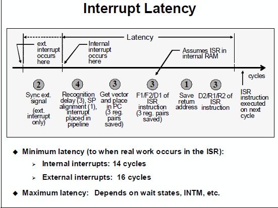
ISR Latency
Consider the following diagram, taken from the C2000 Workshop Material:
- The actual maximum latency will change, as indicated in the below image. Things that can delay an interrupt:
Are interrupts disabled (INTM)? When you take an interrupt this is automatically done - so to allow nested interrupts it has to be cleared.
Is the CPU executing a RPT instruction (single repeat). This cannot be interrupted.
Multiple cycle instructions - for example, if the CPU was just executing a loop - each time through the loop a branch would be taken which could delay an interrupt for 4 cycles. One way to avoid this is to put the CPU into idle so it will be in the same state each time the interrupt comes in.
Is code execution in wait stated memory
Is stack in wait stated memory. It is rare to have data memory with a wait state in c2000 but say, just as an example, the stack was in external memory (XINTF).
Is the stack and the code in the same physical memory block
If the interrupt source is from an external pin, then any qualification on the pin will add to the delay.
Setting up the PIE vector table
- Q: How do I link my ISR function to the corresponding interrupt flag bit?
The C/C++ Header Files and Peripheral Examples are a great place to start as they provide peripheral examples with the interrupts already configured. No matter if you are using SPI, SCI, ADC, etc. this software package has interrupt examples. In controlSUITE these examples can be found in the device_support directory for your particular device.
The ITRAP Interrupt
- Q: What causes an illegal (ITRAP) interrupt?
An invalid instruction is decoded (this includes invalid addressing modes).
The opcode value 0x0000 is decoded. This opcode corresponds to the ITRAP0 instruction.
The opcode value 0xFFFF is decoded. This opcode corresponds to the ITRAP1 instruction.
A 32-bit operation attempts to use the @SP register addressing mode.
Address mode setting AMODE=1 and PAGE0=1which is an illegal combination.
- Q: How can I debug an ITRAP?
An ITRAP is often a sign of stack overflowing or a buffer overflowing. To quickly see if it is the stack you can fill the region with a known value and then run the application. By the addresses written to you will be able to see how big the stack grew.
This application note has a method for using on-chip resources to detect when a stack overflow occurs: Online Stack Overflow Detection on the TMS320C28x DSP (spra820).
Make sure code isn’t getting too close to the end of a valid memory block (which is followed by invalid memory). This is explained in the device errata.
Make sure that if any code is being loaded into flash and run from RAM that it is properly copied to RAM before the function is called.
Make sure the CPU is not pre-fetching into the code security password location.
Insert a return instruction into the ISR. Set a breakpoint on this instruction and then step to see where the code came from.
Another option is to look at the stack. When you take an illegal instruction trap, registers are automatically pushed on the stack, including the return address. By looking at the return address value on the stack, you can find out where the ITRAP occurred.