|
C2000Ware Digital Power SDK
5.03.00.00
|


|
|
C2000Ware Digital Power SDK
5.03.00.00
|
|
Data Structures | |
| struct | SPLL_3PH_SRF_LPF_COEFF |
| Defines the coefficients for a loop filter. More... | |
| struct | SPLL_3PH_SRF |
| Defines the SPLL_3PH_SRF structure. More... | |
Functions | |
| static void | SPLL_3PH_SRF_init (float32_t grid_freq, float32_t delta_t, SPLL_3PH_SRF *spll_obj) |
| Initialize SPLL_3PH_SRF module. More... | |
| static void | SPLL_3PH_SRF_reset (SPLL_3PH_SRF *spll_obj) |
| Reset SPLL_3PH_SRF module. More... | |
| static void | SPLL_3PH_SRF_run (float32_t v_q, SPLL_3PH_SRF *spll_obj) |
| Run SPLL_3PH_SRF module. More... | |
Typedefs | |
| typedef float | float32_t |
| typedef long double | float64_t |
Macros | |
| #define | C2000_IEEE754_TYPES |
The Software Phase Lock Loop based on synchronous reference frame (SPLL_3PH_SRF) API provides a set of functions that implements a software phase lock loop based on based on synchronous reference frame for grid connection to three phase grid.

It is common to transform three phase time varying system to a dc system, in a rotating reference frame with the help of transforms. Assuming the below equation for the three phase quantities the sequence of the voltages is
![\[ V_{a}->V_{b}->V_{c} \]](form_54.png)
, and the frequency is ω.


The three phase quantities are first reduced to an orthogonal component system ( alpha, beta also called stationary reference frame), by taking the projections of the three phase quantities on the orthogonal axis. This is called the clark transform:
![\[ V_{\alpha\beta 0} = T_{abc->\alpha\beta 0} V_{abc} \]](form_55.png)

Now the net voltage vector can be assumed to be making an angle θ with the orthogonal reference frame and rotating at a frequency of ω. Thus the system can be reduced to DC by taking projection of the orthogonal components on the rotating reference frame:
![\[ V_{dq0} = T_{\alpha\beta 0->dq0} V_{\alpha\beta 0} \]](form_56.png)
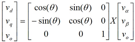

Using trigonometric identities:

For the PLL to be almost locked, i.e.
![\[\theta \]](form_57.png)
is equal to
![\[\omega t \]](form_58.png)
the quadrature component can be linearized as follows:
![\[ v_{q} \approx (\omega t - \theta)\]](form_59.png)
As seen in the above analysis the q component is zero for a balanced three phase system. This property is exploited in the phase locked loop for three phase grid connected application. The q component is used as the error signal for the PLL to track to the appropriate phase. First the three phase quantities are transformed into the rotating reference frame and the q component is used as the phase detect. A low pass filter/PI is then used to eliminate steady state error and the output fed to a VCO which generated the angle and sine values.
A functional diagram of a PLL is shown in the figure below, which consists of a phase detect (PD) consisting of park transform, a loop filter(LPF) and a voltage controlled oscillator(VCO):
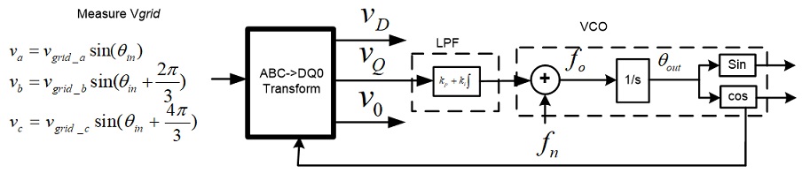
The ABC-> DQ0 transform is kept separate from the PLL structure.
Using equations from the SPLL_1ph description above using settling time to be 30ms and the error band to be 5% and damping ratio to be 0.7 we can obtain the natural frequency to be 119.014 and then back substituting we get
![\[ K_{p} = 166.6\]](form_60.png)
and
![\[ K_{i} = 27755.55\]](form_61.png)
Back substituting these values into the digital loop filter coefficients we get:
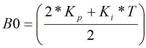
and
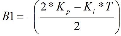
Now for 50Khz run rate for the PLL, B0= 166.877556 and B1= -166.322444
An excel file is also provided to tune this values.
The following is a sequence of steps that can be followed to use the SPLL_3PH_SRF API library functions in an existing C program. For a set of code examples that illustrates the use of this library, see the examples in the Digial Power SDK.
Before you can using the library you must add the libraries directory path as a searchable directory in the project include options. This can be done by right-clicking on the project in the Project Explorer window, selecting "Properties". In the window that opens, navigate to "Build, C2000 Compiler, Include Options". In the include path
window, click on the green add directory path button on the right and enter the path to the Digital Power SDK libraries directory.
This allows CCS to search the entire directory for library files.
Once that is done you should follow these steps to incorporate the library into a project:
There is only one module in this package, the APIs can be referenced at SPLL_3PH_SRF. The module headers are located at spll_3ph_srf.h.
| #define C2000_IEEE754_TYPES |
Definition at line 47 of file spll_3ph_srf.h.
| typedef float float32_t |
Definition at line 52 of file spll_3ph_srf.h.
| typedef long double float64_t |
Definition at line 53 of file spll_3ph_srf.h.
|
inlinestatic |
Initialize SPLL_3PH_SRF module.
| grid_freq | The grid frequency |
| delta_t | 1/Frequency of calling the PLL routine |
| *spll_obj | The SPLL_3PH_SRF structure |
Definition at line 92 of file spll_3ph_srf.h.
|
inlinestatic |
Reset SPLL_3PH_SRF module.
| *spll_obj | The SPLL_3PH_SRF structure |
Definition at line 114 of file spll_3ph_srf.h.
|
inlinestatic |
Run SPLL_3PH_SRF module.
| v_q | Q component of the grid voltage |
| *spll_obj | The SPLL_3PH_SRF structure |
Definition at line 133 of file spll_3ph_srf.h.
 1.8.17