|
C2000Ware Digital Power SDK
5.03.00.00
|


|
|
C2000Ware Digital Power SDK
5.03.00.00
|
|
Data Structures | |
| struct | SPLL_1PH_NOTCH_COEFF |
| Defines the SPLL_1PH_NOTCH_COEFF structure. More... | |
| struct | SPLL_1PH_NOTCH_LPF_COEFF |
| Defines the SPLL_1PH_NOTCH_LPF_COEFF structure. More... | |
| struct | SPLL_1PH_NOTCH |
| Defines the SPLL_1PH_NOTCH structure. More... | |
Functions | |
| static void | SPLL_1PH_NOTCH_reset (SPLL_1PH_NOTCH *spll_obj) |
| Resets internal data to zero,. More... | |
| static void | SPLL_1PH_NOTCH_coeff_calc (SPLL_1PH_NOTCH *spll_obj, float32_t c1, float32_t c2) |
| Calculates the coefficients for SPLL_1PH_NOTCH filter. More... | |
| static void | SPLL_1PH_NOTCH_config (SPLL_1PH_NOTCH *spll_obj, float32_t acFreq, float32_t isrFrequency, float32_t lpf_b0, float32_t lpf_b1, float32_t c1, float32_t c2) |
| Configures the SPLL_1PH_NOTCH module. More... | |
| static void | SPLL_1PH_NOTCH_run (SPLL_1PH_NOTCH *spll_obj, float32_t acValue) |
| Runs the SPLL_1PH_NOTCH module. More... | |
Typedefs | |
| typedef float | float32_t |
| typedef long double | float64_t |
Macros | |
| #define | C2000_IEEE754_TYPES |
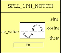
The Software Phase Lock Loop for Single Phase Grid with NOTCH filter (SPLL_1PH_NOTCH) API provides a set of functions that calculate the instantaneous phase of a single phase grid. It also computes the sine and cosine values of the grid that can then be used in the closed loop control.
A functional diagram of a PLL is shown in the Figure 7.2, which consists of a phase detect (PD), a loop filter (LPF) and a voltage controlled oscillator (VCO) block
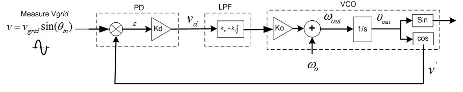
A sinusoidal measured value of the grid is given by,
![\[ v = v_{grid}sin({\theta_{in}}) = v_{grid}sin({\omega_{grid}}t + {\theta_{grid}}) \]](form_10.png)
Now let the VCO output be,
![\[ v' = cos({\theta_{out}}) = cos({\omega_{PLL}}t + {\theta_{PLL}}) \]](form_11.png)
Phase Detect block multiplies the VCO output and the measured input value to get,
![\[ v_{d} = \frac{K_{d}v_{grid}}2 [sin(({\omega_{grid}} - {\omega_{PLL}})t + ({\theta_{grid}} - {\theta_{PLL}})) + sin(({\omega_{grid}} + {\omega_{PLL}})t + ({\theta_{grid}} + {\theta_{PLL}}))] \]](form_12.png)
The output of PD block has information of the phase difference. However, it has a high frequency component as well.
Thus the second block the loop filter, which is nothing but a PI controller is used which to low pass filter the high frequency components. Thus the output of the PI is
![\[ \overline{v_{d}} = \frac{K_{d}v_{grid}}2 sin(({\omega_{grid}} - {\omega_{PLL}})t + ({\theta_{grid}} - {\theta_{PLL}})) \]](form_13.png)
For steady state operation, ignore the  term, and sin(Θ) = Θ the linearized error is given as,
![\[ err = \frac{v_{grid}({\theta_{grid}} - {\theta_{PLL}})}2 \]](form_15.png)
Small signal analysis is done using the network theory, where the feedback loop is broken to get the open loop transfer equation and then the closed loop transfer function is given by
Thus the PLL transfer function can be written as follows
![\[ H_{o}(s) = \frac{{\theta_{out}}(s)}{{\theta_{in}(s)}} = \frac{LF(s)}{s + LF(s)} = \frac{v_{grid}(k_{p}s + \frac{k_{p}}{T_{i}})}{s^2 + v_{grid}k_{p}s + v_{grid}\frac{k_{p}}T_{i}} \]](form_16.png)
![\[ E_{o}(s) = \frac{V_{d}(s)}{\theta_{in}(s)} = 1- H_{o}(s) = \frac{s}{s + LF(s)} = \frac{s^2}{s^2 + k_{p}s + \frac{k_{p}}{T_{i}}} \]](form_17.png)
The closed loop phase transfer function represents a low pass filter characteristics, which helps in attenuating the higher order harmonics. From the error transfer function it is clear that there are two poles at the origin which means that it is able to track even a constant slope ramp in the input phase angle without any steady state error.
Comparing the closed loop phase transfer function to the generic second order system transfer function
![\[ H(s) = \frac{2\zeta\omega_{n}s + {\omega_{n}}^2}{s^2 + 2\zeta\omega_{n}s + {\omega_{n}}^2} \]](form_18.png)
Now comparing this with the closed loop phase transfer function, we can get the natural frequency and the damping ration of the linearalized PLL.
![\[ \omega_{n} = \sqrt{\frac{v_{grid}K_{p}}{T_{i}}}\]](form_19.png)
![\[ \zeta = \sqrt{\frac{v_{grid}{T_{i}}{K_{p}}}{4}} \]](form_20.png)
Note in the PLL the PI serves dual purpose
Now if the carrier is high enough in frequency, the low pass characteristics of the PI are good enough and one does not have to worry about low frequency passing characteristics of the LPF and only tune for the dynamic response of the PI. However as the grid frequency is very low (50Hz-60Hz) the roll off provided by the PI is not satisfactory enough and introduces high frequency element to the loop filter output, which affects the performance of the PLL.
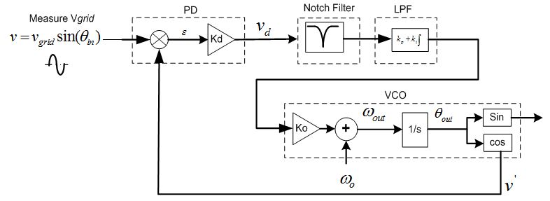
Therefore a notch filter is used at the output of the Phase Detect block which attenuates the twice the grid frequency component very well. An adaptive notch filter is used to selectively notch the exact frequency in case there are variations in the grid frequency.
In this case, the PI tuning can be done solely based on dynamic response of the PLL and not worry about the LPF characteristics.
The Loop Filter or PI is implemented as a digital controller with the following equation
![\[ ylf[n] = ylf[n-1] * A1 + ynotch[n] * B0 + ynotch[n-1] * B1 \]](form_21.png)
Using Z transform, this equation can be written as
![\[ \frac{ylf(z)}{ynotch(z)} = \frac{B0 + B1*z^{-1}}{1-z^{-1}} \]](form_22.png)
Now the laplace transform of the loop filter from the analog domain is
![\[ \frac{ylf(s)}{ynotch(s)} = K_{p} + \frac{K_{i}}s \]](form_23.png)
Now using Bi-linear transformation  =>
=>
![\[ \frac{ylf(z)}{ynotch(z)} = \frac{(\frac{2*K_{p}+K_{i}*T}{2}) - (\frac{2*K_{p}-K_{i}*T}{2})z^{-1}}{1-z^{-1}} \]](form_25.png)
where T = Sampling Time
Now the question is how to select an appropriate value for the proportional and integral gain. Now the step response to a general second order equation i.e.
 is given as:
Ignoring the LHP zero from the above equation, now the settling time is given as the time it takes for the response to settle between an error band, let's say this error is ∂, then
![\[ 1-\partial = 1-ce^{-\sigma{t_{s}}} => \partial = ce^{-\sigma{t_s}} => t_{s} = \frac{1}{\sigma} * ln(\frac{c}{\sigma}) \]](form_28.png)
Where  and
and  and
and 
Now using settling time to be 30ms and the error band to be 5% and damping ratio to be 0.7 we can obtain the natural frequency to be 119.014 and then back substituting we get  and
and 
Back substituting these values into the digital loop filter coefficients, we get:

Now for 50Khz run rate for the PLL, B0= 166.877556 and B1= -166.322444
The software module provides the structure for a software based PLL to be used in a single phase grid tied application using the method described in the Software Phase PLL with Notch Filter figure.
Design of the notch filter is achieved using discretizing the notch filter equation from s domain:  where
where 
Using zero order hold i.e.  we get
![\[ H_{nf}(s) = \frac{z^2 + (2\zeta_{2}\omega_{n}T - 2)z + (-2\zeta_{2}\omega_{n}T + {\omega_{n}}^2{T^2} + 1)}{z^2 + (2\zeta_{1}\omega_{n}T -2)z + (-2\zeta_{1}\omega_{n}T + {\omega_{n}}^2{T^2} + 1)} = \frac{B_{0}+ B_{1}z^{-1} + B_{2}z^{-2}}{A_{0}+ A_{1}z^{-1} +A_{2}z^{-2}} \]](form_38.png)
Hence, the coefficients for the notch filter can be adaptively changed as the grid frequency varies. The coefficients are chosen such that attenuation at twice the grid frequency is steep without affecting other frequencies.
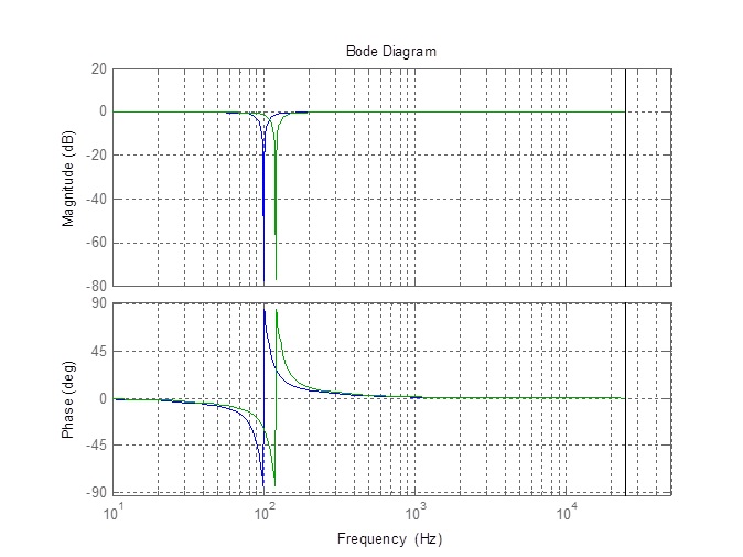
Taking  , and
, and  and
and  , the response of the notch is as shown below for 50 and 60Hz grid where the coefficients are calculated based on the grid frequency estimate.


The following is a sequence of steps that can be followed to use the SPLL_1PH_notch API library functions in an existing C program. For a set of code examples that illustrates the use of this library, see the examples in the Digial Power SDK.
Before you can using the library you must add the libraries directory path as a searchable directory in the project include options. This can be done by right-clicking on the project in the Project Explorer window, selecting "Properties". In the window that opens, navigate to "Build, C2000 Compiler, Include Options". In the include path
window, click on the green add directory path button on the right and enter the path to the Digital Power SDK libraries directory.
There is only one module in this package, the APIs can be referenced at SPLL_1PH_NOTCH. The module headers are located at spll_1ph_notch.h.
| #define C2000_IEEE754_TYPES |
Definition at line 48 of file spll_1ph_notch.h.
| typedef float float32_t |
Definition at line 53 of file spll_1ph_notch.h.
| typedef long double float64_t |
Definition at line 54 of file spll_1ph_notch.h.
|
inlinestatic |
Resets internal data to zero,.
| *spll_obj | The SPLL_1PH_NOTCH structure pointer |
Definition at line 106 of file spll_1ph_notch.h.
|
inlinestatic |
Calculates the coefficients for SPLL_1PH_NOTCH filter.
| *spll_obj | The SPLL_1PH_NOTCH structure pointer |
| c1 | c1 Notch paramater |
| c2 | c2 Notch Parameter |
Definition at line 136 of file spll_1ph_notch.h.
|
inlinestatic |
Configures the SPLL_1PH_NOTCH module.
| *spll_obj | The SPLL_1PH_NOTCH structure pointer |
| acFreq | Nominal AC frequency for the SPLL Module |
| isrFrequency | Nominal AC frequency for the SPLL Module |
| lpf_b0 | B0 coefficient of LPF of SPLL |
| lpf_b1 | B1 coefficient of LPF of SPLL |
| c1 | c1 Notch paramater |
| c2 | c2 Notch Parameter |
Definition at line 174 of file spll_1ph_notch.h.
|
inlinestatic |
Runs the SPLL_1PH_NOTCH module.
| *spll_obj | The SPLL_1PH_NOTCH structure pointer |
| acValue | AC grid voltage in per unit (pu) |
Definition at line 199 of file spll_1ph_notch.h.
 1.8.17