Example Applications
This section provides an overview of the TI-OpenThread out-of-box example applications and instructions on how to run them.
Note
All TI-OpenThread example applications are supported for the following
three boards: CC26X2R1_LAUNCHXL, CC1352R1_LAUNCHXL and
CC1352P2_LAUNCHXL. By default the READMEs below will link to the
CC26X2R1_LAUNCHXL board. If a different board is intended to be used,
just replace the board name in the path to find the corresponding README
document.
Project Configurations
Some example applications supports both an FTD and an MTD device
configuration, and therefore two types of project configurations exist for
such example applications: one with the <name>_ftd_* naming convention for
the FTD configuration, and one with the <name>_mtd_* naming convention
for the MTD naming convention. For example, the CLI example has both a
cli_ftd_* and a cli_mtd_* project configuration for a FTD and MTD
configuration, respectively.
All example applications support the CCS, GCC, IAR, and TI-CLANG
toolchains, and therefore four project configurations exist for each example
application: one with the *_ccs suffix which uses CCS, one with the
*_gcc suffix which uses GCC, one with the *_iar suffix which uses
IAR, and one with the *_ticlang suffix which uses TI-CLANG.
Both Thread device configuration and toolchain selection is configured separately, and therefore multiple projects are available for some example projects as a combination of said configurations.
Factory Reset
Some of the example applications contain convenience functionality to reset the non-volatile storage on the internal flash, as well as a reset to some stored factory image. Refer to each respective section for instructions on how to perform each kind of factory reset.
Reset of Non-Volatile Storage
Non-volatile storage (NVS) in the internal flash stores information about the Thread network which allows Thread devices to restart network operations after a reset without user intervention. However, in order for a Thread device to forget a Thread network it has been commissioned to, the NVS must be erased.
For the end-product examples, a convenience functionality has been added in order to easily erase NVS and quickly start fresh. Given that the running application supports this functionality, do the following steps to reset NVS:
- Hold down the right button (BTN-2) on the CC13x2 or CC26x2 LaunchPad.
- While holding down the right button, press the reset button.
- At startup the application will check the pin state and jump to the invalidate-NVS routine.
Warning
Reset of NVS does not erase the actual application image on the internal flash.
Revert to Factory Image
OAD-enabled examples can revert back to a factory image, if a factory image is present on the external flash. Given that a factory image is stored, do the following steps to reset to the factory image:
Given that the running application supports this functionality, do the following steps to reset to factory image:
- Hold down the left button (BTN-1) on the CC13x2 or CC26x2 LaunchPad.
- While holding down the left button, press the reset button.
- At startup the application will check the pin state and jump to the reset-to-factory-image routine.
Warning
Reverting to the factory image does not erase NVS in the internal flash.
The application should check that a valid factory image is present before reverting. This can be done by ensuring there is valid metadata in external flash page 0. See OAD External Flash Image Header for more information.
Common User Interface
The common user interface (CUI) is a module on application examples.
Serial communication is utilized for the user to configure certain parameters,
and to display various device information.
The Thread application examples which use CUI implement the functionality
in both its respective application file and tiop_ui.c.
The CUI consists of a series of circular menus that are navigated with the arrow keys. To enter a submenu, press the Enter key. Adjustable values on submenus (e.g. PAN ID, channel) may be changed using the keyboard (e.g. arrow keys, letters, numbers) and pressing Enter afterwards.
Note
When editing a value, the Esc key may be used to exit edit mode. While on a submenu, the Esc key may be used to return to the main menu.
The CUI is also dependent on the capabilities of the compiled device. For example, a Full Thread Device may form a network while a Minimal Thread Device must join a network.
It is recommended to use PuTTY as the serial terminal program for these sample applications because the serial output has been verified to be formatted correctly in this program. For serial port setup, select 115200 for baud rate and disable flow control.
Below is an overview of the menus common across all CUI-enabled examples.
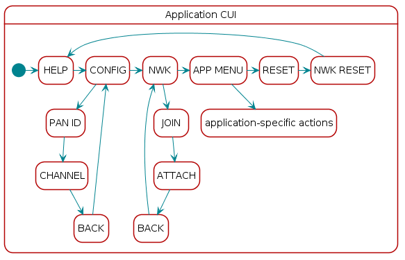
Figure 22. CUI Overview
Help Screen
The initial screen displays the application name and leads to the Help Screen, which outlines the generic functionality of the keys throughout the application. The following sections describe the specific functionality of the keys for each menu screen.
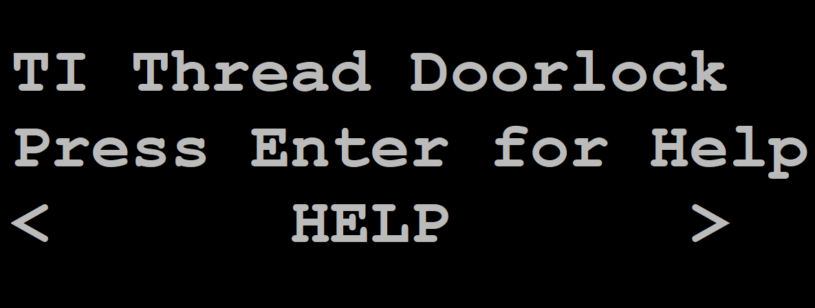
Figure 23. Initial screen

Figure 24. Help screen
| Welcome and Help Screens | ||
|---|---|---|
| Key | Function | Comment |
| Left/Right Arrow Keys | Menu navigation | Move to previous/next screen |
| Enter | Help | Press Enter to show the help screen. Press Enter again to go back to the Welcome Screen. |
Information Screen
The lower portion of the screen displays various information about the device such as the 64-bit unique identifier, network name, and PAN ID.
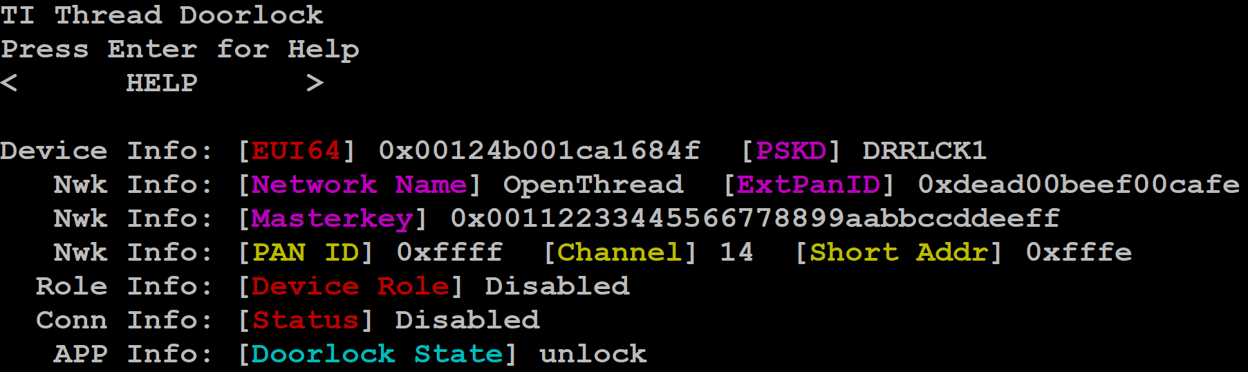
Figure 25. Info screen example
Device Info
The Device Info line shows information about the device.
- EUI64: Extended Unique Identifier of the device (64 bits), which the device will use for commissioning.
- PSKD: Pre-shared Key of Device, which the device will use for commissioning.
Nwk Info
The Nwk Info lines show information of the network which this device belongs to.
- Network Name: The human-readable name of this network.
- ExtPanID: The 64-bit extended PANID of this network.
- Masterkey: The 128-bit masterkey in use by the network.
- PAN ID: The 16-bit PAN ID of this network.
- Channel: The 2.4 GHz channel occupied by this network.
- Short Addr: The 16-bit network address assigned to this device.
Role Info
The role info line shows the current role of the device:
- Disabled: Thread stack is disabled; the default initial state of the device on reset.
- Detached: Device is not part of a Thread network.
- Child: Device is operating as a child in its Thread network.
- Router: Device is operating as a router in its Thread network.
- Leader: Device is operating as the leader in its Thread network.
Conn Info
The conn info line shows the connection status of the device:
- Disabled: No connection; the default initial state of the connection on reset.
- Joining Nwk: Device is attempting to connect to a network.
- Nwk Joined: Device has successfully joined a network.
- Join Failure: Device failed an attempt to connect to a network.
APP Info
The app info line shows the application-specific state of the device. For more details, refer to the application’s respective README.
Config
The Configure menu contains sub-menus that allow the user to change common network parameters.
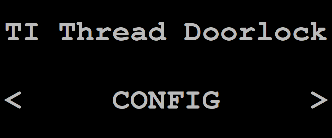
Figure 26. Configure Menu
PAN ID
The PAN ID menu allows the user to configure the PAN ID of the network to join or form. A value of 0xFFFF indicates an unspecified PAN ID. After this device is part of a network, this value indicates the PAN ID of that network, and changing this value is not valid.
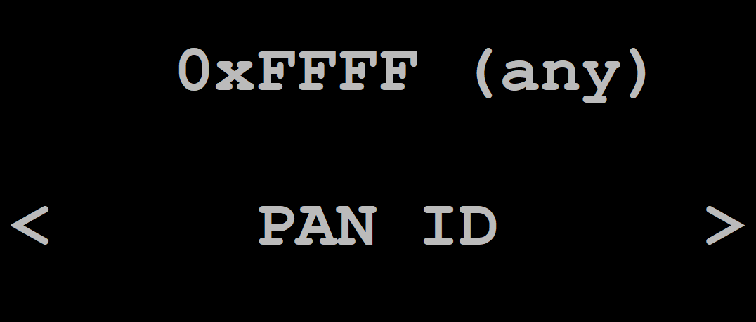
Figure 27. PAN ID Screen
| PAN ID - view mode | ||
|---|---|---|
| Key | Function | Comment |
| Left/Right | Menu navigation | Move to previous/next screen |
| Enter | Select | Enter edit mode |
| PAN ID - edit mode | ||
|---|---|---|
| Key | Function | Comment |
| Left/Right | Digit navigation | Move to previous/next digit |
| Up/Down | Value change | Increase/decrease the value of the highlighted digit |
| Keyboard (hex values) | Value change | Set the selected byte of the PAN ID to the key pressed |
| Enter | Select | Save and enter view mode |
Channel
The channel of the network that this device will attempt to attach or form. Once joined to a network, this value indicates the channel of that network.
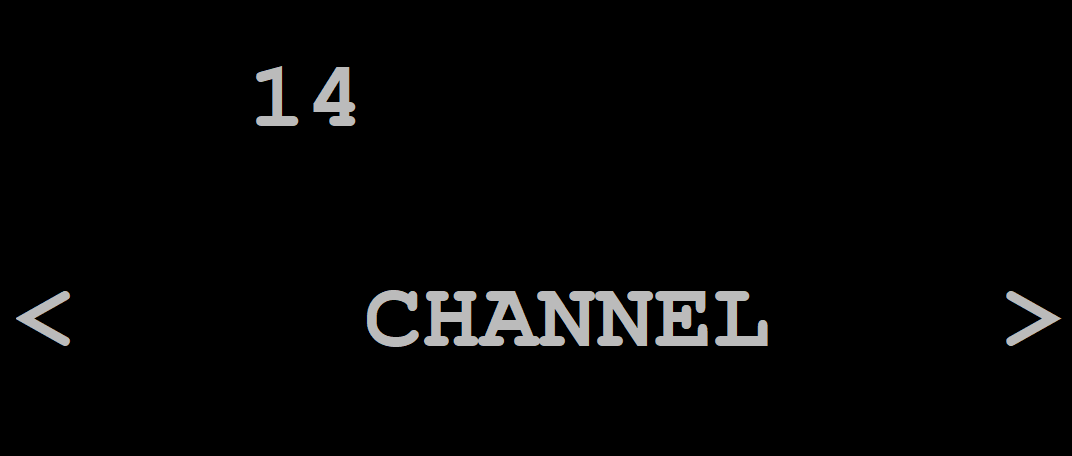
Figure 28. Channel Screen
| Channel - view mode | ||
|---|---|---|
| Key | Function | Comment |
| Enter | Select | Enter edit mode |
| Channel - edit mode | ||
|---|---|---|
| Key | Function | Comment |
| Enter | Select | Save and enter view mode |
| Left/Right | Select digit | Move to previous/next digit |
| Number key | Set channel | Channel must be between 11 and 26 (inclusively) |
NWK
The Network menu contains sub-menus that allow the user to start network operations.
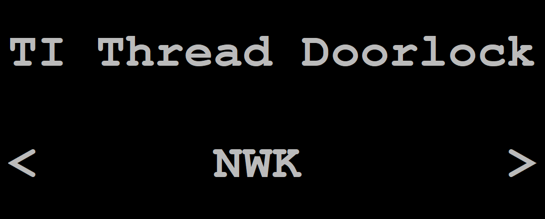
Figure 29. Network Menu
Join
Start the network join process via the commissioner using the pre-configured PSKd. Press Enter on this menu to trigger this.
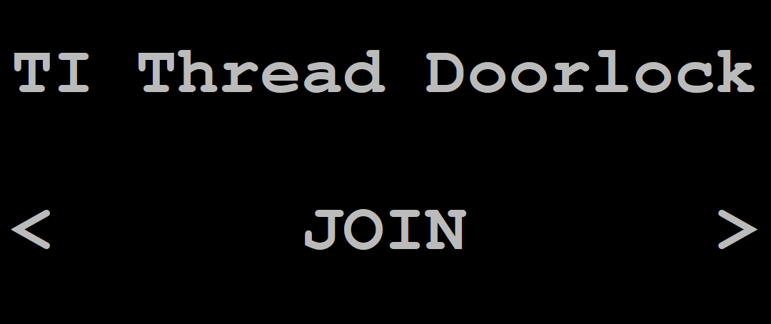
Figure 30. Join Menu
Attach
Application attempts to bring up the interface and setup the Thread network, using the current device dataset. Press Enter on this menu to trigger this.
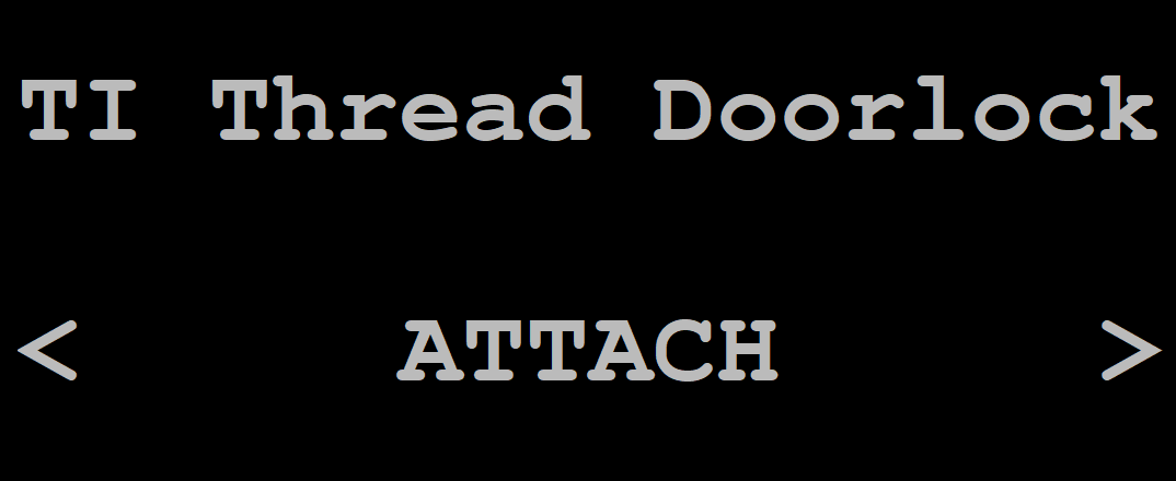
Figure 31. Attach Menu
App Menu
The App menu contain application-specific sub-menus and actions. Refer to the README of the respective application example for details on what actions are supported.
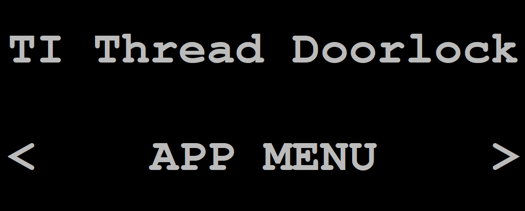
Figure 32. App Menu
Reset
The Reset menu may be used to reset the OpenThread Instance without clearing out previous network data. Press Enter on this menu to trigger this.
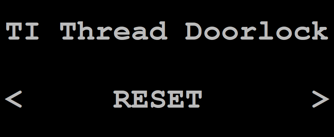
Figure 33. Reset Menu
NWK Reset
The Network Reset menu may be used to reset the OpenThread Instance and clear out the previous network data. Press Enter on this menu to trigger this.
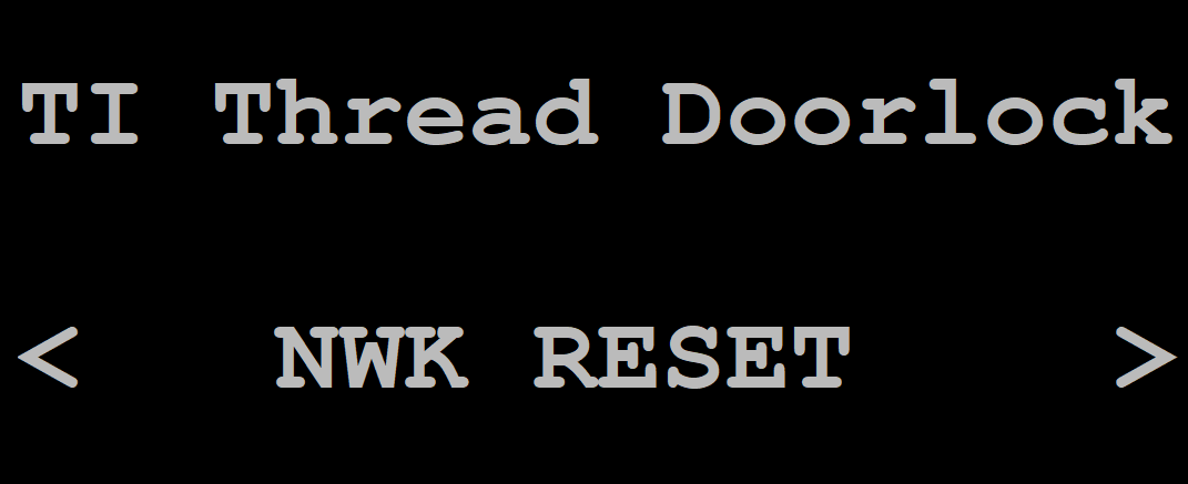
Figure 34. NWK Reset Menu
End Product Examples
Door Lock
The door lock project presents a simple CoAP server representing a door lock. Only an MTD configuration is available. The door lock example is best used with a Sharp Memory LCD and microSD BoosterPack, but also can be used with only the basic UART log.
There are also OAD-enabled variants of the Door Lock example. For more information, please refer to Section Door Lock OAD.
Shade
The shade project presents a simple CoAP server representing window blinds. Only an MTD configuration is available. The shade example is best used with a Sharp Memory LCD and microSD BoosterPack, but also can be used with only the basic UART log.
Temperature Sensor
The Temperature Sensor project presents a simple CoAP server and client representing an embedded temperature sensor. Only an MTD configuration is available.
Thermostat
The thermostat project presents a simple CoAP server representing a thermostat. Only an FTD configuration is available. The thermostat example is best used with a Sharp Memory LCD and microSD BoosterPack, but also can be used with only the basic UART log.
Other Examples
Command Line Interface (CLI)
The CLI projects can be used to interact with and explore the different aspects of the Thread protocol. Both an FTD and MTD configuration is available. The CLI interface OpenThread presents is also used for certification with the Thread Group test harness.
There is also an OAD-enabled variant of the CLI example. For more information, please refer to Section OAD CLI.
Network Co-Processor (NCP)
The NCP project is used to connect the TI-OpenThread to a host processor. Only an FTD configuration is available. For more information about the interface between the NCP and host processor, see Section NCP Interface.
Border Router
The border router example is a basic implementation of a Thread Border Router, which bridges IP traffic from an external IP network to the Thread network and vice-versa. A Thread Border Router also enables off-mesh commissioning of new devices into the Thread network.
OAD Server
The OAD Server example is a C program meant to run on a Linux environment which is connected to a border router. For more information, see Section OAD Server.