Create a TI-OpenThread OAD Image
OAD-Enable a Thread Image
Section TI-OpenThread OAD Examples shows an overview of available
OAD-enabled example applications. The oad_cli example will be used for
this section as a case study for adding OAD support to an existing project.
Changes to linker script
One of the major changes between the downloadable CLI example application and the regular CLI example is the linker script. Changes include: reserving space for the metadata headers, reserving the last page of flash, and moving the CCFG.
To reserve the necessary memory for the image header, a memory section was
added to the flash map. See line 4 in Listing 22..
As mentioned in OAD Image Header, the required size and position is
fixed at the base of the flash layout and is 0x100 bytes in size.
Another memory section is reserved for the reset vectors. To ensure that the
application’s reset vectors are placed at 0x100, this section is
explicitly placed. See line 5 in Listing 22.. The
length of that section is set at 0x100 to ensure that more than enough
room is reserved for the reset vectors.
Finally, as noted in Boot Image Manager (BIM), we need to reserve enough space for
BIM itself. This is defined as the last page in our flash map. This
reservation can be seen by noticing that the FLASH_BULK section is 3 pages
smaller than the flash size. See line 6 in
Listing 22.. A section is also added for a debug
BIM and CCFG on line 9. This is used to place a pre-built BIM and CCFG.
Note
This OAD example application reserves two flash pages for the NV storage, that is the second and third to last flash page. This is different than the regular CLI example, but both approaches are valid.
1 2 3 4 5 6 7 8 9 10 | MEMORY
{
/* Application stored in and executes from internal flash */
FLASH_IMG_HDR : origin = FLASH_BASE + 0x000 , length = 0x100
FLASH (RX) : origin = FLASH_BASE + 0x100 , length = (FLASH_SIZE - 0x100)
FLASH_BIM_CCFG (RX) : origin = FLASH_BIM_CCFG_BASE , length = FLASH_BIM_CCFG_SIZE
/* Application uses internal RAM for data */
SRAM (RWX) : origin = RAM_BAS , length = RAM_SIZE
GPRAM (RWX) : origin = GPRAM_BASE , length = GPRAM_SIZE
}
|
Then the two new sections need to be filled with information. Place the OAD image header in the flash image header section. And, move the interrupt vectors into the new flash entry section. Don’t forget to rename the placements for the old flash section.
1 2 3 4 5 6 7 8 9 10 11 12 13 14 15 | SECTIONS
{
.oad_image_header : > FLASH_IMG_HDR
GROUP > FLASH
{
.intvecs
/* ... application flash sections ... */
.flash_end_address
}
.bim_oad_debug_image_bin : > FLASH_BIM_CCFG
/* ... application SRAM sections ... */
}
|
Remove the now unused ccfg placement. For the ti-cgt toolchain examples, this
usually shows up as .ccfg : > FLASH (HIGH) in the linker script.
Remove or change project files
Remove the ccfg.c file from the project. This will prevent the
CCFG from being added to the final built image. The CCFG is now owned
by the BIM project, and the CC13x2 or CC26x2 will use that CCFG.
Add the oad_image_header.c and oad_image_header.h files to your
project. These can be copied from the oad_cli project directly. These
source files define the OAD image header that is placed at the origin of the
image.
Optionally add the bim_oad_debug_image_bin.c and
bim_oad_debug_image_bin.h files to your project. These are not required
for creating a downloadable image. These source files add a C array at the end
of flash that is a known good BIM image. This only serves to make programming
and debugging within the CCS environment easy. It may be advisable for you to
look at the BIM project, or to create your own.
Consult the main_oad.c source file in the oad_cli project for a
mechanism to erase the CRC metadata in the image header. This will allow you
to invalidate your running image and force BIM to reload the factory image.
Add the post-build steps to the project
Finally, we need to define the post-build step that converts the *.out
file to a *.hex file, and lastly creates the final downloadable *.bin
file.
First we need to define the location of the OAD image tool. Open the project
properties by right clicking on the project in the project explorer and
selecting Properties. Then navigate to the Linked Resources page by
selecting Resource → Linked Resources. From there, add a new path
variable by clicking New... as seen below.
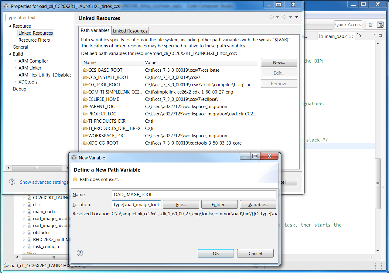
Figure 74. Defining the OAD image tool location
Note
CCS may complain that the location does not exist, this is due to the
${OsType} build variable in the path. This variable is only valid at
build time.
Add the post-build steps to the configuration. In the project’s Properties,
navigate to the Build page by selecting Build. Then select the Steps
tab and add the following lines to the Post-build steps text box.
${CG_TOOL_HEX} -order MS --memwidth=8 --romwidth=8 --intel -o ${ProjName}.hex ${ProjName}.out
${OAD_IMAGE_TOOL} --verbose ccs ${PROJECT_LOC}/${ConfigName} 7 -hex1 ${ProjName}.hex -o ${ProjName}_oad
This will add the necessary steps to flatten the image into a *.hex, and
create the downloadable *.bin binary.
Creating a Production Image
A production image is an image that is ready for flashing at the factory, and to be released in a commercial OAD enabled product.
Change to Release BIM
By default, the projects in the SimpleLink CC13x2 / 26x2 SDK will use a debug version of the BIM. This is helpful for evaluation of the TI OAD solution, but is not recommended for a production OAD build for the following reasons:
- The debug configuration of BIM will not check the CRC of the image before booting. This removes a layer of redundancy in the system in favor of allowing the developer to load an OAD image straight from the IDE.
- The debug configuration has LED output that may not be desirable in production.
Warning
When switching to a release configuration of BIM, images loaded straight from the IDE will not run after a reset. This is expected behavior as the OAD image tool is responsible for populating the CRC field in these images. See the Loading a Production Image section for more information.
Additionally, it may be desirable to remove the secondary device trim in the application for production images. See Device trim for more information.
Loading a Production Image
Images loaded straight from the IDE will not have a valid CRC or signature. However, the OAD image tool will add the CRC and signature automatically at the completion of each build. Refer to Figure 61. for a diagram of the build process.
Before loading the application, be sure to load the release BIM project. This can be flashed via the BIM’s hex file in UNIFLASH.
Warning
If flashing the BIM image (or a merged image containing BIM) using
uniflash, be sure that the Keep CCFG data box is not checked
(Settings & Utilities → Download). BIM will use a custom
CCFG, so it is important that any existing image on the device is removed.
Another safeguard is the mass erase the device before starting with OAD.
In release configurations, it is necessary to load the device using the
*_oad.bin application file that is output by the oad_image_tool using
UNIFLASH.
- The binary from the tool will be placed in the build folder alongside the default
.outfile.
The address offset should be 0x0000000 as shown in the screen capture below
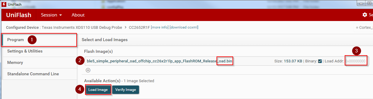
Note the following error is benign and can be ignored for OAD images. Verify the device has booted correctly by verifying the terminal output.
