Power Configuration
Overview
The following sections provides different code and variables to be considered when designing a low-power mesh network. Power management functionality is handled by the TI-RTOS power driver and used by the peripheral drivers (e.g. UART, SPI, I2C, etc). For power consumption measurements on Z-Stack, refer to SWRA625.
TX Power Configuration
The following sections provide configurations which can be implemented to modify the application’s TX power, to achieve a greater distance the device can communicate with other devices on the network, or lower the application’s power consumption for a longer battery life in your device.
Changing TX Power Level
By default, the CC1352R/CC2652R has the TX power set to 5 dBm. P-devices,
having a Power Amplifier integrated in the device, have the TX power set to 20
dBm by default. To modify the TX power level at runtime to a different value,
the best place to insert the following code is inside of the ZCL application
zcl[application]_Init function. For example, the switch project would be
zclSampleSw_Init.
zstack_sysSetTxPowerReq_t powerReq;
zstack_sysSetTxPowerRsp_t powerRsp;
powerReq.requestedTxPower = 0; // Set power to 0 dBm

Zstackapi_sysSetTxPowerReq(appServiceTaskId, &powerReq, &powerRsp);
The maximum power level supported for a regular CC1352R/CC2652R device in IEEE 802.15.4 mode is 5 dBm. A P-type device can support up to 20 dBm. This code snippet can be used for any example project (excluding Green Power projects).
Boost Mode
In order for the Power Amplifier to output the maximum 20 dBm TX power in IEEE mode, Boost Mode is enabled inside of the TX power tables in the application. Boost Mode increases the VDDR from 1.7 V to 1.95 V, which increases the maximum TX power output from 17 dBm to 20 dBm, while also increasing current consumption by 15%. The TX power tables are located inside the mac_user_config_[DEVICE]r1_rftable.h file. You can find this file for the CC1352P device in the SDK installation directory:
C:\ti\<SimpleLink SDK>\source\ti\ti154stack\common\boards\mac_user_config_cc13x2r1_rftable.h
Note
Configuring Boost Mode should only be done when using a device with an integrated Power Amplifier (e.g. a CC1352P device).
The list txPowerTable_ieee_CC1352P1 defines all available TX power
levels to be used when the PA is enabled. The
RF_TxPowerTable_HIGH_PA_ENTRY define has the following structure:
RF_TxPowerTable_HIGH_PA_ENTRY(bias, ibboost, boost, coefficient, ldotrim)
To disable Boost Mode, set the boost value to 0 inside the TX power table for the desired TX power level entry.
Additional Optimizations
Z-Stack provides several parameters which control the device runtime behavior.
The Application Preprocessor Configuration section discusses several of these parameters.
One additional parameter which can be useful for cutting out extra power
consumption is BOARD_DISPLAY_USE_UART. Undefining this parameter
will disable UART communication for application information.
Additionally, shutting down the external flash can save on current consumption.
To shutdown external flash, you should add the following line inside
of main():
Board_shutDownExtFlash();
Example Application Power Test Definitions
Power consumption use cases have been included inside of the zcl_samplelight
and zcl_samplesw example applications for users to further evaluate the low
power operation of Z-Stack as part of the SimpleLink CC13x2 / 26x2 SDK. To include this feature,
Z_POWER_TEST must be added to the project preprocessor symbols (refer to
Application Preprocessor Configuration for more information) along with
POWER_TEST_TX_PWR set to a valid TX power level for the CC13x2 or CC26x2 being used
and one specific power test case configuration:
POWER_TEST_POLL_ACKPOWER_TEST_DATA_ACKPOWER_TEST_POLL_DATA
The operation and behavior of each will be further explained by the following sections. The LEDs and UI are disabled in these modes for greater power savings, also the devices start commissioning automatically on startup. Otherwise, behavior of the examples, including CC13x2 or CC26x2 LaunchPad BTN-1/2 operation, is the same as described in the Running the Example Applications READMEs.
Average power consumption will vary based on the hardware used. When using a CC13x2 or CC26x2 LaunchPad with an external DC power analyzer (as shown in the provided screenshots) note that all XDS110 jumpers should be removed for accurate results. If taking measurements using EnergyTrace™ software please reference the EnergyTrace User Guide.
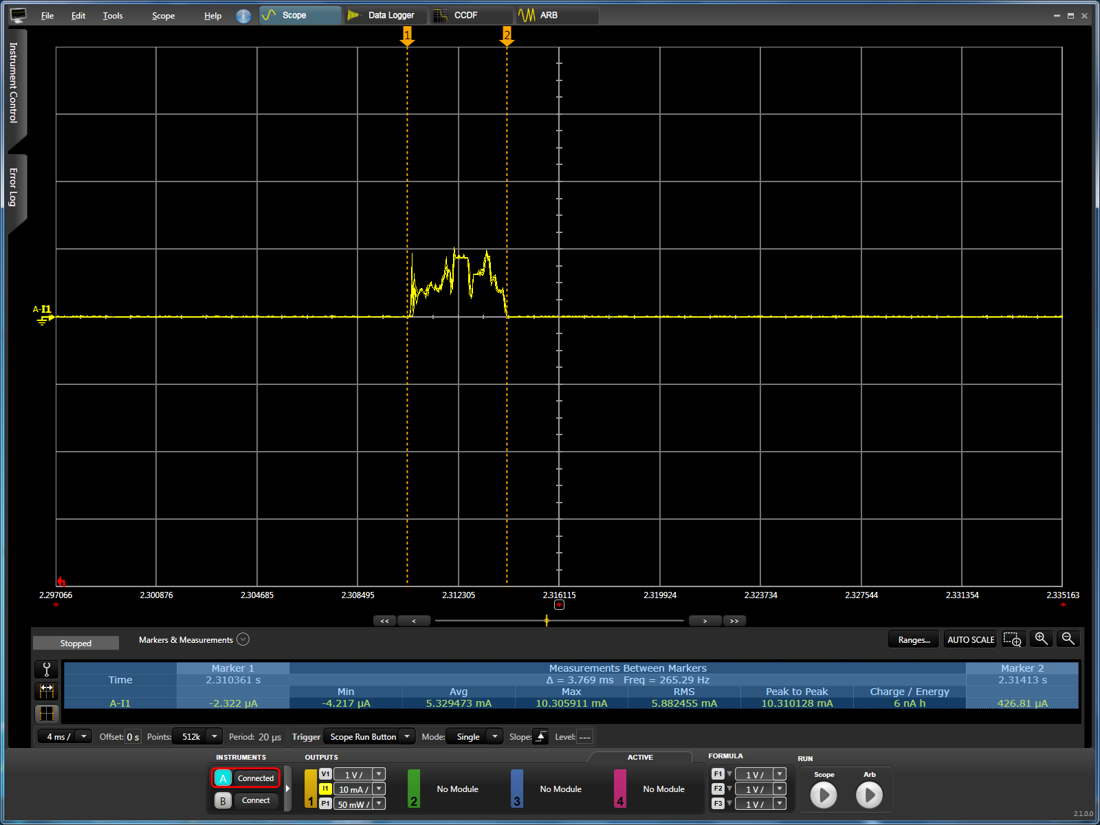
POWER_TEST_POLL_ACK
This test measures the current consumption of a ZED switch as it polls, with no data transferred between either device.
zc_light behavior:
- Form the network and perform steering to open permit joining, but do not commence the finding & binding procedure
- Stay idle and do not buffer any packets from
zed_swafter the ZED joins the network
zed_sw behavior:
- Start steering to search for and join the ZC’s network
- After joining, set
zgPollRateto 5 seconds withZstackapi_sysConfigWriteReq - Send a data poll over-the-air every
zgPollRateseconds
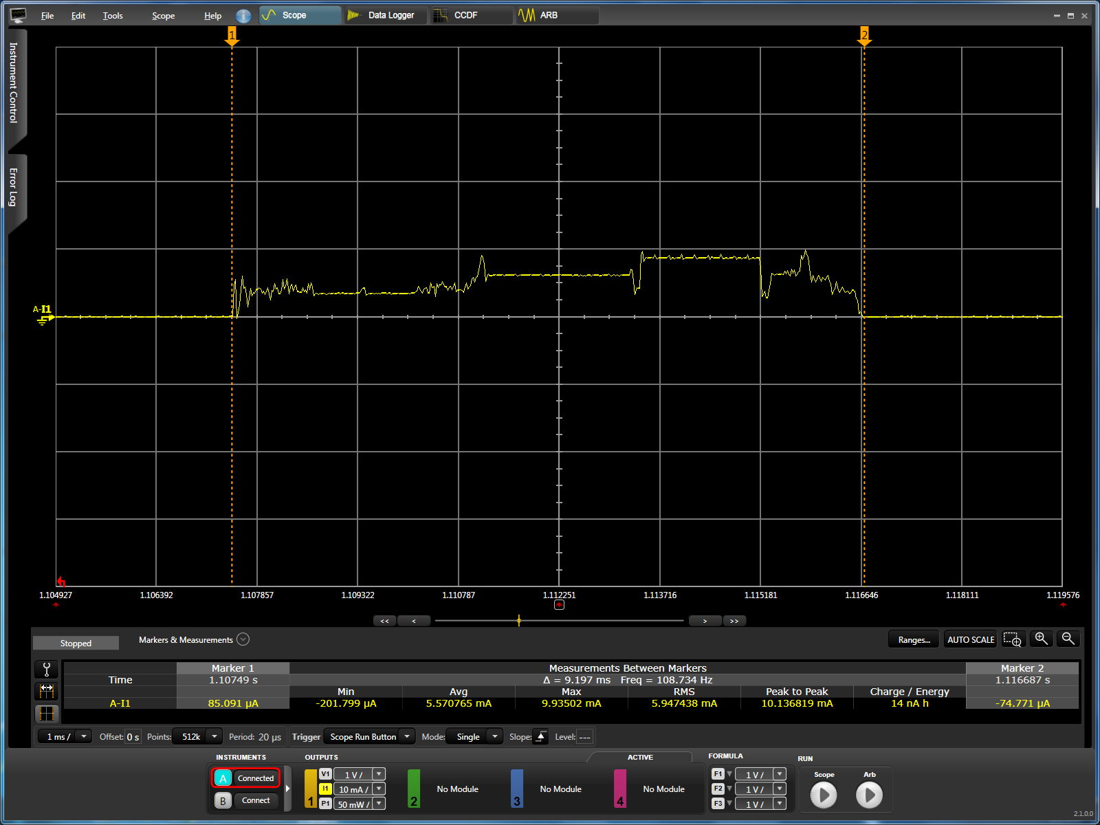
POWER_TEST_DATA_ACK
This test measures the current consumption of a ZED switch as it sends ZCL ON/OFF packets to the ZC light.
zc_light behavior:
- Form the network, perform steering to open permit joining, and begin the Finding & Binding procedure
- Remain idle
zed_sw behavior:
- Start steering to search for and join the ZC’s network
- Once joined, finding & binding is enabled so that a bind may automatically be created on the switch client for the On/Off cluster
- After finding & binding, set
zgPollRateto 0 seconds to disable data reception from the ZC - Send ZCL on/off toggle packets over-the-air every 5 seconds with
OsalPortTimers_startReloadTimerandSAMPLEAPP_POWER_TEST_TOGGLE_EVT
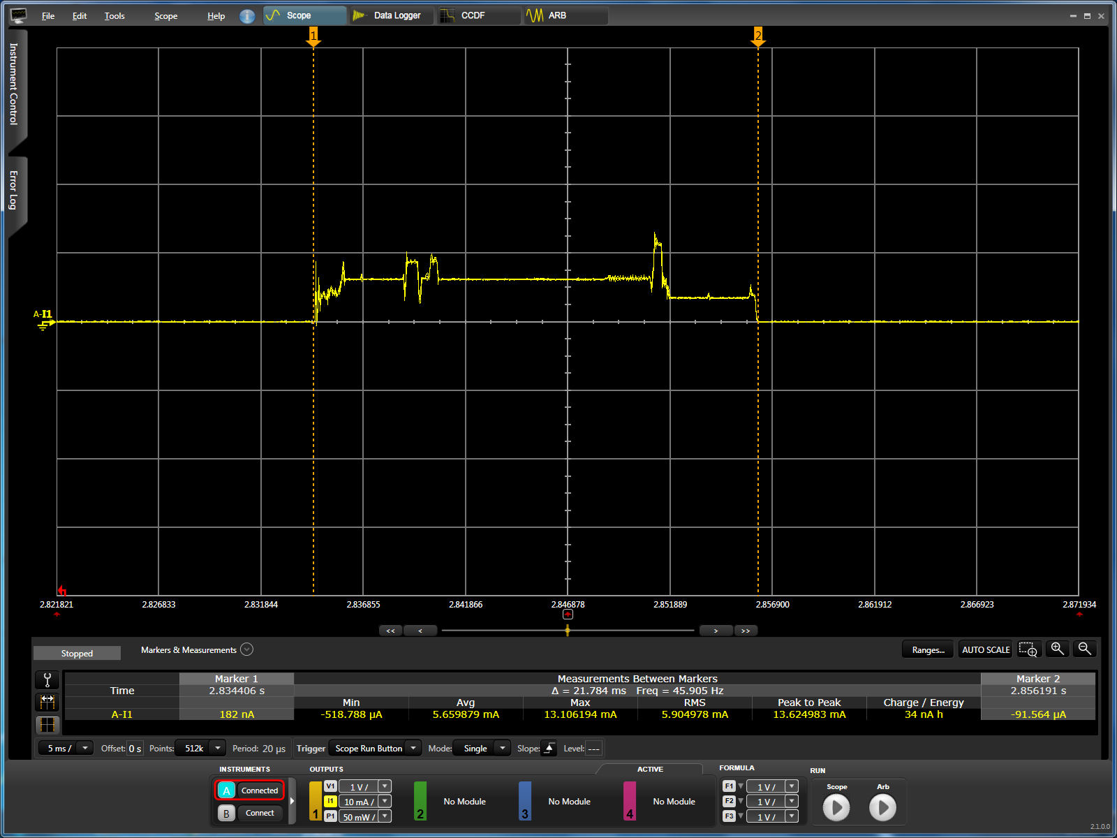
POWER_TEST_POLL_DATA
This test measures the current consumption of a ZED switch as it polls and receives ZCL data from the ZC light
zc_light behavior:
- Form the network and perform steering to open permit joining on startup, but do not find & bind to prevent the ZED switch from sending ZCL On/Off packets
- After the ZED joins the network, process the
zstackmsg_CmdIDs_ZDO_DEVICE_ANNOUNCEto locally save the short address of the ZED - Use
OsalPortTimers_startReloadTimerandSAMPLEAPP_POWER_TEST_ZCL_DATA_EVTto occassionally send ZCL data to the ZED switch withZstackapi_AfDataReq
zed_sw behavior:
- Start steering to search for and join the ZC’s network
- After joining, set
zgPollRateto 5 seconds withZstackapi_sysConfigWriteReq - Send a data poll over-the-air every
zgPollRateseconds and receive ZCL packet from the ZC if it indicates that data is pending
For more information regarding low power operaion of the CC13x2 or CC26x2 with Z-Stack, including battery-less Green Power devices and further practical usage scenarios for battery life estimations, please refer to SWRA625.