|
CC13xx Driver Library
|
|
CC13xx Driver Library
|
Functions | |
| void | IOCPortConfigureSet (uint32_t ui32IOId, uint32_t ui32PortId, uint32_t ui32IOConfig) |
| Set the configuration of an IO port. More... | |
| uint32_t | IOCPortConfigureGet (uint32_t ui32IOId) |
| Get the configuration of an IO port. More... | |
| void | IOCIOShutdownSet (uint32_t ui32IOId, uint32_t ui32IOShutdown) |
| Set wake-up mode from shutdown on an IO port. More... | |
| void | IOCIOModeSet (uint32_t ui32IOId, uint32_t ui32IOMode) |
| Set the IO Mode of an IO Port. More... | |
| void | IOCIOIntSet (uint32_t ui32IOId, uint32_t ui32Int, uint32_t ui32EdgeDet) |
| Setup edge detection and interrupt generation on an IO Port. More... | |
| void | IOCIOPortPullSet (uint32_t ui32IOId, uint32_t ui32Pull) |
| Set the pull on an IO port. More... | |
| void | IOCIOHystSet (uint32_t ui32IOId, uint32_t ui32Hysteresis) |
| Configure hysteresis on and IO port. More... | |
| void | IOCIOInputSet (uint32_t ui32IOId, uint32_t ui32Input) |
| Enable/disable IO port as input. More... | |
| void | IOCIOSlewCtrlSet (uint32_t ui32IOId, uint32_t ui32SlewEnable) |
| Configure slew rate on an IO port. More... | |
| void | IOCIODrvStrengthSet (uint32_t ui32IOId, uint32_t ui32IOCurrent, uint32_t ui32DrvStrength) |
| Configure the drive strength source and current mode of an IO port. More... | |
| void | IOCIOPortIdSet (uint32_t ui32IOId, uint32_t ui32PortId) |
| Setup the Port ID for this IO. More... | |
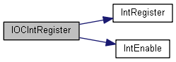
| static void | IOCIntRegister (void(*pfnHandler)(void)) |
| Register an interrupt handler for an IO edge interrupt in the dynamic interrupt table. More... | |
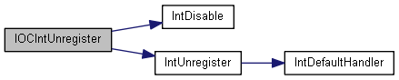
| static void | IOCIntUnregister (void) |
| Unregisters an interrupt handler for a IO edge interrupt in the dynamic interrupt table. More... | |
| void | IOCIntEnable (uint32_t ui32IOId) |
| Enables individual IO edge detect interrupt. More... | |
| void | IOCIntDisable (uint32_t ui32IOId) |
| Disables individual IO edge interrupt sources. More... | |
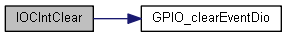
| static void | IOCIntClear (uint32_t ui32IOId) |
| Clears the IO edge interrupt source. More... | |
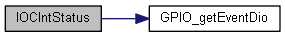
| static uint32_t | IOCIntStatus (uint32_t ui32IOId) |
| Returns the status of the IO interrupts. More... | |
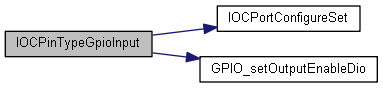
| void | IOCPinTypeGpioInput (uint32_t ui32IOId) |
| Setup an IO for standard GPIO input. More... | |
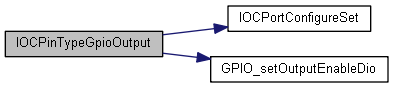
| void | IOCPinTypeGpioOutput (uint32_t ui32IOId) |
| Setup an IO for standard GPIO output. More... | |
| void | IOCPinTypeUart (uint32_t ui32Base, uint32_t ui32Rx, uint32_t ui32Tx, uint32_t ui32Cts, uint32_t ui32Rts) |
| Configure a set of IOs for standard UART peripheral control. More... | |
| void | IOCPinTypeSsiMaster (uint32_t ui32Base, uint32_t ui32Rx, uint32_t ui32Tx, uint32_t ui32Fss, uint32_t ui32Clk) |
| Configure a set of IOs for standard SSI peripheral master control. More... | |
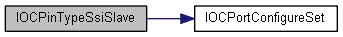
| void | IOCPinTypeSsiSlave (uint32_t ui32Base, uint32_t ui32Rx, uint32_t ui32Tx, uint32_t ui32Fss, uint32_t ui32Clk) |
| Configure a set of IOs for standard SSI peripheral slave control. More... | |
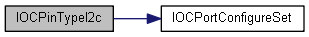
| void | IOCPinTypeI2c (uint32_t ui32Base, uint32_t ui32Data, uint32_t ui32Clk) |
| Configure a set of IOs for standard I2C peripheral control. More... | |
| void | IOCPinTypeAux (uint32_t ui32IOId) |
| Configure an IO for AUX control. More... | |
The Input/Output Controller (IOC) controls the functionality of the pins (called DIO). The IOC consists of two APIs:
For more information on the AON IOC see the AON IOC API.
A DIO is considered "software controlled" if it is configured for GPIO control which allows the System CPU to set the value of the DIO via the GPIO API. Alternatively, a DIO can be "hardware controlled" if it is controlled by other modules than GPIO.
The API functions can be grouped like this:
Configure all settings at the same time:
Configure individual settings:
Handle edge detection events:
Configure IOCs for typical use cases (can also be used as example code):
|
inlinestatic |
Clears the IO edge interrupt source.
The specified IO edge interrupt source is cleared, so that it no longer asserts. This function must be called in the interrupt handler to keep the interrupt from being recognized again immediately upon exit.
| void IOCIntDisable | ( | uint32_t | ui32IOId | ) |
Disables individual IO edge interrupt sources.
This function disables the indicated IO edge interrupt source. Only the sources that are enabled can be reflected to the processor interrupt; disabled sources have no effect on the processor.
| void IOCIntEnable | ( | uint32_t | ui32IOId | ) |
Enables individual IO edge detect interrupt.
This function enables the indicated IO edge interrupt sources. Only the sources that are enabled can be reflected to the processor interrupt; disabled sources have no effect on the processor.
| ui32IOId | is the IO to enable edge detect interrupt for. |
|
inlinestatic |
Register an interrupt handler for an IO edge interrupt in the dynamic interrupt table.
This function registers a function as the interrupt handler for a specific interrupt and enables the corresponding interrupt in the interrupt controller.
Specific IO interrupts must be enabled via IOCIntEnable(). It is the interrupt handler's responsibility to clear the interrupt source.
| pfnHandler | is a pointer to the function to be called when the IOC interrupt occurs. |
|
inlinestatic |
Returns the status of the IO interrupts.
|
inlinestatic |
Unregisters an interrupt handler for a IO edge interrupt in the dynamic interrupt table.
This function does the actual unregistering of the interrupt handler. It clears the handler to be called when an IO edge interrupt occurs.
| void IOCIODrvStrengthSet | ( | uint32_t | ui32IOId, |
| uint32_t | ui32IOCurrent, | ||
| uint32_t | ui32DrvStrength | ||
| ) |
Configure the drive strength source and current mode of an IO port.
The drive strength of an IO is configured by a combination of multiple settings in several modules. The drive strength source ui32DrvStrength is used for controlling drive strength at different supply levels. When set to AUTO the battery monitor (BATMON) adjusts the drive strength to compensate for changes in supply voltage in order to keep IO current constant. Alternatively, drive strength source can be controlled manually by selecting one of three options each of which is configurable in the AON IOC by AONIOCDriveStrengthSet().
Each drive strength source has three current modes: Low-Current (LC), High-Current (HC), and Extended-Current (EC), and typically drive strength doubles when selecting a higher mode. I.e. EC = 2 x HC = 4 x LC.
| ui32IOId | defines the IO to configure. |
| ui32IOCurrent | selects the IO current mode.
|
| ui32DrvStrength | sets the source for drive strength control of the IO port.
|
| void IOCIOHystSet | ( | uint32_t | ui32IOId, |
| uint32_t | ui32Hysteresis | ||
| ) |
Configure hysteresis on and IO port.
This function is used to enable/disable hysteresis on an IO.
| ui32IOId | defines the IO to configure. |
| ui32Hysteresis | enable/disable input hysteresis on IO. |
| void IOCIOInputSet | ( | uint32_t | ui32IOId, |
| uint32_t | ui32Input | ||
| ) |
Enable/disable IO port as input.
This function is used to enable/disable input on an IO.
| ui32IOId | defines the IO to configure. |
| ui32Input | enable/disable input on IO. |
| void IOCIOIntSet | ( | uint32_t | ui32IOId, |
| uint32_t | ui32Int, | ||
| uint32_t | ui32EdgeDet | ||
| ) |
Setup edge detection and interrupt generation on an IO Port.
This function is used to setup the edge detection and interrupt generation on an IO.
| ui32IOId | defines the IO to configure. |
| ui32Int | enables/disables interrupt generation on this IO port. |
| ui32EdgeDet | enables/disables edge detection events on this IO port. |
| void IOCIOModeSet | ( | uint32_t | ui32IOId, |
| uint32_t | ui32IOMode | ||
| ) |
Set the IO Mode of an IO Port.
This function is used to set the input/output mode of an IO.
| ui32IOId | defines the IO to configure. |
| ui32IOMode | sets the port IO Mode. |
| void IOCIOPortIdSet | ( | uint32_t | ui32IOId, |
| uint32_t | ui32PortId | ||
| ) |
Setup the Port ID for this IO.
The ui32PortId specifies which functional peripheral to hook up to this IO.
| void IOCIOPortPullSet | ( | uint32_t | ui32IOId, |
| uint32_t | ui32Pull | ||
| ) |
Set the pull on an IO port.
This function is used to configure the pull on an IO.
| ui32IOId | defines the IO to configure. |
| ui32Pull | enables/disables pull on this IO port. |
| void IOCIOShutdownSet | ( | uint32_t | ui32IOId, |
| uint32_t | ui32IOShutdown | ||
| ) |
Set wake-up mode from shutdown on an IO port.
This function is used to set the wake-up mode from shutdown of an IO.
IO must be configured as input in order for wakeup to work. See IOCIOInputSet().
| ui32IOId | defines the IO to configure. |
| ui32IOShutdown | enables wake-up from shutdown on LOW/HIGH by this IO port. |
| void IOCIOSlewCtrlSet | ( | uint32_t | ui32IOId, |
| uint32_t | ui32SlewEnable | ||
| ) |
Configure slew rate on an IO port.
This function is used to enable/disable reduced slew rate on an IO.
| ui32IOId | defines the IO to configure. |
| ui32SlewEnable | enables/disables reduced slew rate on an output. |
| void IOCPinTypeAux | ( | uint32_t | ui32IOId | ) |
Configure an IO for AUX control.
Use this function to enable AUX to control a specific IO. Please note, that when using AUX to control the IO, the input/output control in the IOC is bypassed and completely controlled by AUX, so enabling or disabling input in the IOC has no effect.
| ui32IOId | is the IO to setup for AUX usage.
|

| void IOCPinTypeGpioInput | ( | uint32_t | ui32IOId | ) |
Setup an IO for standard GPIO input.
Setup an IO for standard GPIO input with the following configuration:
| void IOCPinTypeGpioOutput | ( | uint32_t | ui32IOId | ) |
Setup an IO for standard GPIO output.
Setup an IO for standard GPIO output with the following configuration:
| void IOCPinTypeI2c | ( | uint32_t | ui32Base, |
| uint32_t | ui32Data, | ||
| uint32_t | ui32Clk | ||
| ) |
Configure a set of IOs for standard I2C peripheral control.
| ui32Base | is the base address of the I2C module to connect to the IOs |
| ui32Data | is the I2C data line
|
| ui32Clk | is the I2C input clock
|
| void IOCPinTypeSsiMaster | ( | uint32_t | ui32Base, |
| uint32_t | ui32Rx, | ||
| uint32_t | ui32Tx, | ||
| uint32_t | ui32Fss, | ||
| uint32_t | ui32Clk | ||
| ) |
Configure a set of IOs for standard SSI peripheral master control.
| ui32Base | is the base address of the SSI module to connect to the IOs |
| ui32Rx | is the IO to connect to the SSI MISO line.
|
| ui32Tx | is the IO to connect to the SSI MOSI line.
|
| ui32Fss | is the IO to connect to the SSI FSS line.
|
| ui32Clk | is the IO to connect to the SSI Clock output line.
|

| void IOCPinTypeSsiSlave | ( | uint32_t | ui32Base, |
| uint32_t | ui32Rx, | ||
| uint32_t | ui32Tx, | ||
| uint32_t | ui32Fss, | ||
| uint32_t | ui32Clk | ||
| ) |
Configure a set of IOs for standard SSI peripheral slave control.
| ui32Base | is the base address of the SSI module to connect to the IOs |
| ui32Rx | is the IO to connect to the SSI MOSI line.
|
| ui32Tx | is the IO to connect to the SSI MISO line.
|
| ui32Fss | is the IO to connect to the SSI FSS line.
|
| ui32Clk | is the IO to connect to the SSI Clock input line. |
| void IOCPinTypeUart | ( | uint32_t | ui32Base, |
| uint32_t | ui32Rx, | ||
| uint32_t | ui32Tx, | ||
| uint32_t | ui32Cts, | ||
| uint32_t | ui32Rts | ||
| ) |
Configure a set of IOs for standard UART peripheral control.
The UART pins must be properly configured for the UART peripheral to function correctly. This function provides a typical configuration for those pin(s). Other configurations may work as well depending upon the board setup (for example, using the on-chip pull-ups).
| ui32Base | is the base address of the UART module. |
| ui32Rx | is the IO Id of the IO to use as UART Receive.
|
| ui32Tx | is the IO Id of the IO to use as UART Transmit.
|
| ui32Cts | is the IO Id of the IO to use for UART Clear to send.
|
| ui32Rts | is the IO Id of the IO to use for UART Request to send.
|
| uint32_t IOCPortConfigureGet | ( | uint32_t | ui32IOId | ) |
Get the configuration of an IO port.
This function is used for getting the configuration of an IO.
Each IO port has a dedicated register for setting up the IO. This function returns the current configuration for the given IO.
| void IOCPortConfigureSet | ( | uint32_t | ui32IOId, |
| uint32_t | ui32PortId, | ||
| uint32_t | ui32IOConfig | ||
| ) |
Set the configuration of an IO port.
This function is used to configure the functionality of an IO.
The ui32IOId parameter specifies which IO to configure.
The ui32PortId parameter specifies which functional peripheral to hook up to this IO.
The ui32IOConfig parameter consists of a bitwise OR'ed value of all the available configuration modes
| ui32IOId | defines the IO to configure and must be one of the following: |
| ui32PortId | selects the functional IO port to connect. The available IO ports are:
|
| ui32IOConfig | is the IO configuration consisting of the bitwise OR of all configuration modes:
|
Referenced by IOCPinTypeAux(), IOCPinTypeGpioInput(), IOCPinTypeGpioOutput(), IOCPinTypeI2c(), IOCPinTypeSsiMaster(), IOCPinTypeSsiSlave(), IOCPinTypeUart(), and SetupAfterColdResetWakeupFromShutDownCfg3().
| #define IOC_BOTH_EDGES 0x00030000 |
Referenced by IOCIOIntSet().
| #define IOC_CURRENT_2MA 0x00000000 |
Referenced by IOCIODrvStrengthSet(), and IOCPinTypeI2c().
| #define IOC_CURRENT_4MA 0x00000400 |
Referenced by IOCIODrvStrengthSet().
| #define IOC_CURRENT_8MA 0x00000800 |
Referenced by IOCIODrvStrengthSet().
| #define IOC_FALLING_EDGE 0x00010000 |
Referenced by IOCIOIntSet().
| #define IOC_HYST_DISABLE 0x00000000 |
Referenced by IOCIOHystSet(), and IOCPinTypeI2c().
| #define IOC_HYST_ENABLE 0x40000000 |
Referenced by IOCIOHystSet(), and SetupAfterColdResetWakeupFromShutDownCfg3().
| #define IOC_INPUT_DISABLE 0x00000000 |
Referenced by IOCIOInputSet().
| #define IOC_INPUT_ENABLE 0x20000000 |
Referenced by IOCIOInputSet(), and IOCPinTypeI2c().
| #define IOC_INT_DISABLE 0x00000000 |
Referenced by IOCIOIntSet(), and IOCPinTypeI2c().
| #define IOC_INT_ENABLE 0x00040000 |
Referenced by IOCIOIntSet().
| #define IOC_INT_M 0x00070000 |
| #define IOC_IOID_MASK 0x000000FF |
| #define IOC_IOMODE_INV 0x01000000 |
Referenced by IOCIOModeSet().
| #define IOC_IOMODE_NORMAL 0x00000000 |
Referenced by IOCIOModeSet().
| #define IOC_IOMODE_OPEN_DRAIN_INV 0x05000000 |
Referenced by IOCIOModeSet().
| #define IOC_IOMODE_OPEN_DRAIN_NORMAL 0x04000000 |
Referenced by IOCIOModeSet(), and IOCPinTypeI2c().
| #define IOC_IOMODE_OPEN_SRC_INV 0x07000000 |
Referenced by IOCIOModeSet().
| #define IOC_IOMODE_OPEN_SRC_NORMAL 0x06000000 |
Referenced by IOCIOModeSet().
| #define IOC_IOPULL_DOWN 0x00002000 |
Referenced by IOCIOPortPullSet().
| #define IOC_IOPULL_M 0x00006000 |
| #define IOC_IOPULL_M 0x00006000 |
| #define IOC_IOPULL_UP 0x00004000 |
Referenced by IOCIOPortPullSet(), and IOCPinTypeI2c().
| #define IOC_NO_EDGE 0x00000000 |
Referenced by IOCIOIntSet(), and IOCPinTypeI2c().
| #define IOC_NO_IOPULL 0x00006000 |
Referenced by IOCIOPortPullSet().
| #define IOC_NO_WAKE_UP 0x00000000 |
Referenced by IOCIOShutdownSet(), and IOCPinTypeI2c().
| #define IOC_PORT_AON_CLK32K 0x00000007 |
Referenced by SetupAfterColdResetWakeupFromShutDownCfg3().
| #define IOC_PORT_AUX_IO 0x00000008 |
Referenced by IOCPinTypeAux().
| #define IOC_PORT_GPIO 0x00000000 |
Referenced by IOCPinTypeGpioInput(), and IOCPinTypeGpioOutput().
| #define IOC_PORT_MCU_I2C_MSSCL 0x0000000E |
Referenced by IOCPinTypeI2c().
| #define IOC_PORT_MCU_I2C_MSSDA 0x0000000D |
Referenced by IOCPinTypeI2c().
| #define IOC_PORT_MCU_I2S_AD0 0x00000025 |
| #define IOC_PORT_MCU_I2S_AD1 0x00000026 |
| #define IOC_PORT_MCU_I2S_BCLK 0x00000028 |
| #define IOC_PORT_MCU_I2S_MCLK 0x00000029 |
| #define IOC_PORT_MCU_I2S_WCLK 0x00000027 |
| #define IOC_PORT_MCU_PORT_EVENT0 0x00000017 |
| #define IOC_PORT_MCU_PORT_EVENT1 0x00000018 |
| #define IOC_PORT_MCU_PORT_EVENT2 0x00000019 |
| #define IOC_PORT_MCU_PORT_EVENT3 0x0000001A |
| #define IOC_PORT_MCU_PORT_EVENT4 0x0000001B |
| #define IOC_PORT_MCU_PORT_EVENT5 0x0000001C |
| #define IOC_PORT_MCU_PORT_EVENT6 0x0000001D |
| #define IOC_PORT_MCU_PORT_EVENT7 0x0000001E |
| #define IOC_PORT_MCU_SSI0_CLK 0x0000000C |
Referenced by IOCPinTypeSsiMaster(), and IOCPinTypeSsiSlave().
| #define IOC_PORT_MCU_SSI0_FSS 0x0000000B |
Referenced by IOCPinTypeSsiMaster(), and IOCPinTypeSsiSlave().
| #define IOC_PORT_MCU_SSI0_RX 0x00000009 |
Referenced by IOCPinTypeSsiMaster(), and IOCPinTypeSsiSlave().
| #define IOC_PORT_MCU_SSI0_TX 0x0000000A |
Referenced by IOCPinTypeSsiMaster(), and IOCPinTypeSsiSlave().
| #define IOC_PORT_MCU_SSI1_CLK 0x00000024 |
Referenced by IOCPinTypeSsiMaster(), and IOCPinTypeSsiSlave().
| #define IOC_PORT_MCU_SSI1_FSS 0x00000023 |
Referenced by IOCPinTypeSsiMaster(), and IOCPinTypeSsiSlave().
| #define IOC_PORT_MCU_SSI1_RX 0x00000021 |
Referenced by IOCPinTypeSsiMaster(), and IOCPinTypeSsiSlave().
| #define IOC_PORT_MCU_SSI1_TX 0x00000022 |
Referenced by IOCPinTypeSsiMaster(), and IOCPinTypeSsiSlave().
| #define IOC_PORT_MCU_SWV 0x00000020 |
| #define IOC_PORT_MCU_UART0_CTS 0x00000011 |
Referenced by IOCPinTypeUart().
| #define IOC_PORT_MCU_UART0_RTS 0x00000012 |
Referenced by IOCPinTypeUart().
| #define IOC_PORT_MCU_UART0_RX 0x0000000F |
Referenced by IOCPinTypeUart().
| #define IOC_PORT_MCU_UART0_TX 0x00000010 |
Referenced by IOCPinTypeUart().
| #define IOC_PORT_RFC_GPI0 0x00000033 |
| #define IOC_PORT_RFC_GPI1 0x00000034 |
Referenced by IOCIOPortIdSet(), and IOCPortConfigureSet().
| #define IOC_PORT_RFC_GPO0 0x0000002F |
| #define IOC_PORT_RFC_GPO1 0x00000030 |
| #define IOC_PORT_RFC_GPO2 0x00000031 |
| #define IOC_PORT_RFC_GPO3 0x00000032 |
| #define IOC_PORT_RFC_SMI_CL_IN 0x00000038 |
| #define IOC_PORT_RFC_SMI_CL_OUT 0x00000037 |
| #define IOC_PORT_RFC_SMI_DL_IN 0x00000036 |
| #define IOC_PORT_RFC_SMI_DL_OUT 0x00000035 |
| #define IOC_PORT_RFC_TRC 0x0000002E |
| #define IOC_RISING_EDGE 0x00020000 |
Referenced by IOCIOIntSet().
| #define IOC_SLEW_DISABLE 0x00000000 |
Referenced by IOCIOSlewCtrlSet(), and IOCPinTypeI2c().
| #define IOC_SLEW_ENABLE 0x00001000 |
Referenced by IOCIOSlewCtrlSet().
| #define IOC_STD_INPUT |
Referenced by IOCPinTypeAux(), IOCPinTypeGpioInput(), IOCPinTypeSsiMaster(), IOCPinTypeSsiSlave(), IOCPinTypeUart(), and SetupAfterColdResetWakeupFromShutDownCfg3().
| #define IOC_STD_OUTPUT |
Referenced by IOCPinTypeGpioOutput(), IOCPinTypeSsiMaster(), IOCPinTypeSsiSlave(), and IOCPinTypeUart().
| #define IOC_STRENGTH_AUTO 0x00000000 |
Referenced by IOCIODrvStrengthSet(), and IOCPinTypeI2c().
| #define IOC_STRENGTH_MAX 0x00000300 |
Referenced by IOCIODrvStrengthSet().
| #define IOC_STRENGTH_MED 0x00000200 |
Referenced by IOCIODrvStrengthSet().
| #define IOC_STRENGTH_MIN 0x00000100 |
Referenced by IOCIODrvStrengthSet().
| #define IOC_WAKE_ON_HIGH 0x18000000 |
Referenced by IOCIOShutdownSet().
| #define IOC_WAKE_ON_LOW 0x10000000 |
Referenced by IOCIOShutdownSet().
| #define IOID_0 0x00000000 |
| #define IOID_1 0x00000001 |
| #define IOID_10 0x0000000A |
| #define IOID_11 0x0000000B |
| #define IOID_12 0x0000000C |
| #define IOID_13 0x0000000D |
| #define IOID_14 0x0000000E |
| #define IOID_15 0x0000000F |
| #define IOID_16 0x00000010 |
| #define IOID_17 0x00000011 |
| #define IOID_18 0x00000012 |
| #define IOID_19 0x00000013 |
| #define IOID_2 0x00000002 |
| #define IOID_20 0x00000014 |
| #define IOID_21 0x00000015 |
| #define IOID_22 0x00000016 |
| #define IOID_23 0x00000017 |
| #define IOID_24 0x00000018 |
| #define IOID_25 0x00000019 |
| #define IOID_26 0x0000001A |
| #define IOID_27 0x0000001B |
| #define IOID_28 0x0000001C |
| #define IOID_29 0x0000001D |
| #define IOID_3 0x00000003 |
| #define IOID_30 0x0000001E |
| #define IOID_31 0x0000001F |
Referenced by IOCIntClear(), IOCIntDisable(), IOCIntEnable(), IOCIntStatus(), IOCIODrvStrengthSet(), IOCIOHystSet(), IOCIOInputSet(), IOCIOIntSet(), IOCIOModeSet(), IOCIOPortIdSet(), IOCIOPortPullSet(), IOCIOShutdownSet(), IOCIOSlewCtrlSet(), IOCPinTypeAux(), IOCPinTypeGpioInput(), IOCPinTypeGpioOutput(), IOCPinTypeI2c(), IOCPinTypeSsiMaster(), IOCPinTypeSsiSlave(), IOCPinTypeUart(), IOCPortConfigureGet(), and IOCPortConfigureSet().
| #define IOID_4 0x00000004 |
| #define IOID_5 0x00000005 |
| #define IOID_6 0x00000006 |
| #define IOID_7 0x00000007 |
| #define IOID_8 0x00000008 |
| #define IOID_9 0x00000009 |
| #define IOID_UNUSED 0xFFFFFFFF |
Referenced by IOCPinTypeAux(), IOCPinTypeI2c(), IOCPinTypeSsiMaster(), IOCPinTypeSsiSlave(), and IOCPinTypeUart().
| #define NUM_IO_MAX 32 |
| #define NUM_IO_PORTS 56 |

