|
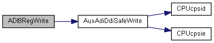
| static void | ADI8RegWrite (uint32_t ui32Base, uint32_t ui32Reg, uint8_t ui8Val) |
| | Write an 8 bit value to a register in an ADI slave. More...
|
| |
| static void | ADI16RegWrite (uint32_t ui32Base, uint32_t ui32Reg, uint16_t ui16Val) |
| | Write a 16 bit value to 2 registers in the ADI slave. More...
|
| |
| static void | ADI32RegWrite (uint32_t ui32Base, uint32_t ui32Reg, uint32_t ui32Val) |
| | Write a 32 bit value to 4 registers in the ADI slave. More...
|
| |
| static uint32_t | ADI8RegRead (uint32_t ui32Base, uint32_t ui32Reg) |
| | Read the value of an 8 bit register in the ADI slave. More...
|
| |
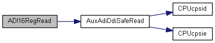
| static uint32_t | ADI16RegRead (uint32_t ui32Base, uint32_t ui32Reg) |
| | Read the value in a 16 bit register. More...
|
| |
| static uint32_t | ADI32RegRead (uint32_t ui32Base, uint32_t ui32Reg) |
| | Read the value in a 32 bit register. More...
|
| |
| static void | ADI8BitsSet (uint32_t ui32Base, uint32_t ui32Reg, uint8_t ui8Val) |
| | Set specific bits in a single 8 bit ADI register. More...
|
| |
| static void | ADI16BitsSet (uint32_t ui32Base, uint32_t ui32Reg, uint16_t ui16Val) |
| | Set specific bits in 2 x 8 bit ADI slave registers. More...
|
| |
| static void | ADI32BitsSet (uint32_t ui32Base, uint32_t ui32Reg, uint32_t ui32Val) |
| | Set specific bits in 4 x 8 bit ADI slave registers. More...
|
| |
| static void | ADI8BitsClear (uint32_t ui32Base, uint32_t ui32Reg, uint8_t ui8Val) |
| | Clear specific bits in an 8 bit ADI register. More...
|
| |
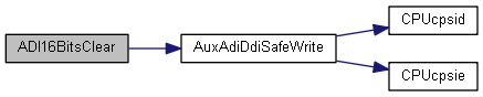
| static void | ADI16BitsClear (uint32_t ui32Base, uint32_t ui32Reg, uint16_t ui16Val) |
| | Clear specific bits in two 8 bit ADI register. More...
|
| |
| static void | ADI32BitsClear (uint32_t ui32Base, uint32_t ui32Reg, uint32_t ui32Val) |
| | Clear specific bits in four 8 bit ADI register. More...
|
| |
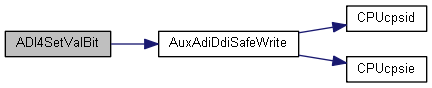
| static void | ADI4SetValBit (uint32_t ui32Base, uint32_t ui32Reg, bool bWriteHigh, uint8_t ui8Mask, uint8_t ui8Val) |
| | Set a value on any 4 bits inside an 8 bit register in the ADI slave. More...
|
| |
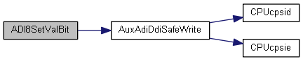
| static void | ADI8SetValBit (uint32_t ui32Base, uint32_t ui32Reg, uint16_t ui16Mask, uint16_t ui16Val) |
| | Set a value on any bits inside an 8 bit register in the ADI slave. More...
|
| |
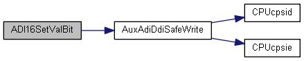
| static void | ADI16SetValBit (uint32_t ui32Base, uint32_t ui32Reg, uint32_t ui32Mask, uint32_t ui32Val) |
| | Set a value on any bits inside an 2 x 8 bit register aligned on a half-word (byte) boundary in the ADI slave. More...
|
| |
| void | SafeHapiVoid (FPTR_VOID_VOID_T fPtr) |
| |
| void | SafeHapiAuxAdiSelect (FPTR_VOID_UINT8_T fPtr, uint8_t ut8Signal) |
| |
| static void ADI16SetValBit |
( |
uint32_t |
ui32Base, |
|
|
uint32_t |
ui32Reg, |
|
|
uint32_t |
ui32Mask, |
|
|
uint32_t |
ui32Val |
|
) |
| |
|
inlinestatic |
Set a value on any bits inside an 2 x 8 bit register aligned on a half-word (byte) boundary in the ADI slave.
This function allows 2 byte (16 bit) access to the ADI slave registers.
Use this function to write any value in the range 0-15 bits aligned on a half-word (byte) boundary. Fx. for writing the value 0b101 to bits 1 and 3 the ui32Val = 0x000A and the ui32Mask = 0x000E. Bits 0 and 5-15 will not be affected by the operation, as the corresponding bits are not set in the ui32Mask.
- Note
- AUX_ADI4_BASE : Both the AUX module and the clock for the AUX SMPH module must be enabled before calling this function.
- Parameters
-
| ui32Base | is the base address of the ADI port. |
| ui32Reg | is the Least Significant Register in the ADI slave that will be affected by the write operation. |
| ui32Mask | is the mask defining which of the 16 bit that should be overwritten. The mask must be defined in the lower half of the 32 bits. |
| ui32Val | is the value to write. The value must be defined in the lower half of the 32 bits. |
- Returns
- None
- See also
- ADI4SetValBit(), ADI8SetValBit()
814 uint32_t ui32RegOffset;
817 ASSERT(ADIBaseValid(ui32Base));
819 ASSERT(!(ui32Val & 0xFFFF0000));
820 ASSERT(!(ui32Mask & 0xFFFF0000));
824 ui32RegOffset = ADI_O_MASK16B + ((ui32Reg << 1) & 0xFC);
830 HWREG(ui32Base + ui32RegOffset) = (ui32Mask << 16) | ui32Val;
#define ASSERT(expr)
Definition: debug.h:73
#define ADI_SLAVE_REGS
Definition: adi.h:77
static void AuxAdiDdiSafeWrite(uint32_t nAddr, uint32_t nData, uint32_t nSize)
Safely write to AUX ADI/DDI interfaces using a semaphore.
Definition: ddi.h:137
| static void ADI4SetValBit |
( |
uint32_t |
ui32Base, |
|
|
uint32_t |
ui32Reg, |
|
|
bool |
bWriteHigh, |
|
|
uint8_t |
ui8Mask, |
|
|
uint8_t |
ui8Val |
|
) |
| |
|
inlinestatic |
Set a value on any 4 bits inside an 8 bit register in the ADI slave.
This function allows halfbyte (4 bit) access to the ADI slave registers. The parameter bWriteHigh determines whether to write to the lower or higher part of the 8 bit register.
Use this function to write any value in the range 0-3 bits aligned on a half byte boundary. Fx. for writing the value 0b101 to bits 1 to 3 the ui8Val = 0xA and the ui8Mask = 0xE. Bit 0 will not be affected by the operation, as the corresponding bit is not set in the ui8Mask.
- Note
- AUX_ADI4_BASE : Both the AUX module and the clock for the AUX SMPH module must be enabled before calling this function.
- Parameters
-
| ui32Base | is the base address of the ADI port. |
| ui32Reg | is the Least Significant Register in the ADI slave that will be affected by the write operation. |
| bWriteHigh | defines which part of the register to write in.
true: Write upper half byte of register.false: Write lower half byte of register.
|
| ui8Mask | is the mask defining which of the 4 bits that should be overwritten. The mask must be defined in the lower half of the 8 bits of the parameter. |
| ui8Val | is the value to write. The value must be defined in the lower half of the 8 bits of the parameter. |
- Returns
- None
- See also
- ADI8SetValBit(), ADI16SetValBit
709 uint32_t ui32RegOffset;
712 ASSERT(ADIBaseValid(ui32Base));
715 ASSERT(!(ui8Mask & 0xF0));
719 ui32RegOffset = ADI_O_MASK4B + (ui32Reg << 1) + (bWriteHigh ? 1 : 0);
725 HWREGB(ui32Base + ui32RegOffset) = (ui8Mask << 4) | ui8Val;
#define ASSERT(expr)
Definition: debug.h:73
#define ADI_SLAVE_REGS
Definition: adi.h:77
static void AuxAdiDdiSafeWrite(uint32_t nAddr, uint32_t nData, uint32_t nSize)
Safely write to AUX ADI/DDI interfaces using a semaphore.
Definition: ddi.h:137
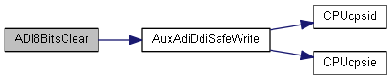
| static void ADI8BitsClear |
( |
uint32_t |
ui32Base, |
|
|
uint32_t |
ui32Reg, |
|
|
uint8_t |
ui8Val |
|
) |
| |
|
inlinestatic |
Clear specific bits in an 8 bit ADI register.
This function will clear bits in a register in the analog domain. The access to the registers in the analog domain is either 8, 16 or 32 bit aligned, but arranged in chunks of 32 bits. You can only do 16 bit access on registers 0-1 / 2-3, etc. Similarly 32 bit accesses are always performed on register 0-3 / 4-7 etc. Addresses for the registers and values being written to the registers will be truncated according to this access scheme.
- Note
- This operation is write only for the specified register. This function is used to clear bits in a specific 8 bit register in the ADI slave. Only bits in the selected register are affected by the operation.
-
AUX_ADI4_BASE : Both the AUX module and the clock for the AUX SMPH module must be enabled before calling this function.
- Parameters
-
| ui32Base | is ADI base address. |
| ui32Reg | is the base registers to clear the bits in. |
| ui8Val | is the 8 bit one-hot encoded value specifying which bits to clear in the register. |
- Returns
- None
- See also
- ADI16BitsClear(), ADI32BitsClear()
Referenced by AUXADCDisable().
552 uint32_t ui32RegOffset;
555 ASSERT(ADIBaseValid(ui32Base));
560 ui32RegOffset = ADI_O_CLR;
566 HWREGB(ui32Base + ui32RegOffset + ui32Reg) = ui8Val;
#define ASSERT(expr)
Definition: debug.h:73
#define ADI_SLAVE_REGS
Definition: adi.h:77
static void AuxAdiDdiSafeWrite(uint32_t nAddr, uint32_t nData, uint32_t nSize)
Safely write to AUX ADI/DDI interfaces using a semaphore.
Definition: ddi.h:137
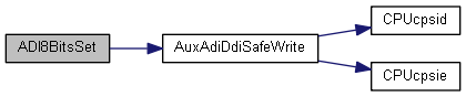
| static void ADI8BitsSet |
( |
uint32_t |
ui32Base, |
|
|
uint32_t |
ui32Reg, |
|
|
uint8_t |
ui8Val |
|
) |
| |
|
inlinestatic |
Set specific bits in a single 8 bit ADI register.
This function will set bits in a single register in the analog domain. The access to the registers in the analog domain is either 8, 16 or 32 bit aligned, but arranged in chunks of 32 bits. You can only do 16 bit access on registers 0-1 / 2-3, etc. Similarly 32 bit accesses are always performed on register 0-3 / 4-7 etc. Addresses for the registers and values being written to the registers will be truncated according to this access scheme.
- Note
- This operation is write only for the specified register. This function is used to set bits in a specific 8 bit register in the ADI slave. Only bits in the selected register are affected by the operation.
-
AUX_ADI4_BASE : Both the AUX module and the clock for the AUX SMPH module must be enabled before calling this function.
- Parameters
-
| ui32Base | is ADI base address. |
| ui32Reg | is the base register to assert the bits in. |
| ui8Val | is the 8 bit one-hot encoded value specifying which bits to set in the register. |
- Returns
- None
- See also
- ADI16BitsSet(), ADI32BitsSet()
Referenced by AUXADCDisableInputScaling(), AUXADCEnableAsync(), and AUXADCEnableSync().
399 uint32_t ui32RegOffset;
402 ASSERT(ADIBaseValid(ui32Base));
407 ui32RegOffset = ADI_O_SET;
413 HWREGB(ui32Base + ui32RegOffset + ui32Reg) = ui8Val;
#define ASSERT(expr)
Definition: debug.h:73
#define ADI_SLAVE_REGS
Definition: adi.h:77
static void AuxAdiDdiSafeWrite(uint32_t nAddr, uint32_t nData, uint32_t nSize)
Safely write to AUX ADI/DDI interfaces using a semaphore.
Definition: ddi.h:137