3.3.4. Kernel Drivers
3.3.4.1. ADC
Introduction
An analog-to-digital converter (abbreviated ADC) is a device that uses sampling to convert a continuous quantity to a discrete time representation in digital form.
The TSC_ADC_SS (Touchscreen_ADC_subsystem) is an 8 channel general purpose ADC, with optional support for interleaving Touch Screen conversions. The TSC_ADC_SS can be used and configured in one of the following application options:
- 8 general purpose ADC channels
- 4 wire TS, with 4 general purpose ADC channels
- 5 wire TS, with 3 general purpose ADC channels
ADC used is 12 bit SAR ADC with a sample rate of 200 KSPS (Kilo Samples Per Second). The ADC samples the analog signal when “start of conversion” signal is high and continues sampling 1 clock cycle after the falling edge. It captures the signal at the end of sampling period and starts conversion. It uses 12 clock cycles to digitize the sampled input; then an “end of conversion” signal is enabled high indicating that the digital data ADCOUT<11:0> is ready for SW to consume. A new conversion cycle can be initiated after the previous data is read. Please note that the ADC output is positive binary weighted data.
Convert Analog voltage to Digital
To cross verify the digital values read use,
D = Vin * (2^n - 1) / Vref
Where:
D = Digital value
Vin = Input voltage
n = No of bits
Vref = reference voltage
Ex: Read value on channel AIN4 for input voltage supplied 1.01:
Formula:
D = 1.01 * (2^12 -1 )/ 1.8
D = 2297.75
Accessing ADC Pins on TI EVMs
AM335x EVM
On top of EVM, on LCD daughter board, J8 connector can be used, where ADC channel input AIN0-AN7 pins are brought out. For further information of J8 connector layout please refer to EVM schematics here
Beaglebone/Beaglebone Black
On BeagleBone platform, P9 expansion header can be used. For further information on expansion header layout please refer to the Beaglebone schematics here
Driver Configuration
You can enable ADC driver in the kernel as follows.
Device Drivers  --->
         [*]  Industrial I/O support  --->
                  [*]  Enable buffer support within IIO
                       Analog to digital converters  --->
                               <*> TI's AM335X ADC driver
Should the entry “TI’s AM335X ADC driver” be missing the MFD component —>
Device Drivers  --->
    Multifunction device drivers  --->
        <M> TI ADC / Touch Screen chip support
Building as Loadable Kernel Module
- In-case if you want to build the driver as module, use <M> instead of <*> during menuconfig while selecting the drivers (as shown below). For more information on loadable modules refer Loadable Module HOWTO
Device Drivers  --->
         [M]  Industrial I/O support  --->
                  [*]  Enable buffer support within IIO
                       Analog to digital converters  --->
                               <M> TI's AM335X ADC driver
- Use “make modules” during kernel build to build the ADC driver as
module. The module should be present in
drivers/iio/adc/ti_am335x_adc.ko. - The driver should autoload on filesystem boot. If not, load the driver using
modprobe ti_am335x_adc.ko
Device Tree
ADC device tree data is added in
file(arch/arm/boot/dts/am335x-evm.dts) as shown below.
&tscadc {
        adc {
                ti,adc-channels = <4 5 6 7>;
        };
};
- This example is using channels AIN4, AIN5, AIN6, and AIN7 are used by ADC. The remaining channels (0 to 3) are used by TSC.
You can find the source code for ADC here
Usage
To test ADC, Connect a DC voltage supply to each of the AIN0 through AIN7 pins (based on your channel configuration), and vary voltage between 0 and 1.8v reference voltage.
CAUTION Make sure that the voltage supplied does not cross 1.8v
On loading the module you would see the IIO device created
root@arago-armv7:~# ls -al /sys/bus/iio/devices/iio\:device0/
drwxr-xr-x    5 root     root             0 Nov  1 22:06 .
drwxr-xr-x    4 root     root             0 Nov  1 22:06 ..
drwxr-xr-x    2 root     root             0 Nov  1 22:06 buffer
-r--r--r--    1 root     root          4096 Nov  1 22:06 dev
-rw-r--r--    1 root     root          4096 Nov  1 22:06 in_voltage4_raw
-rw-r--r--    1 root     root          4096 Nov  1 22:06 in_voltage5_raw
-rw-r--r--    1 root     root          4096 Nov  1 22:06 in_voltage6_raw
-rw-r--r--    1 root     root          4096 Nov  1 22:06 in_voltage7_raw
-r--r--r--    1 root     root          4096 Nov  1 22:06 name
lrwxrwxrwx    1 root     root             0 Nov  1 22:06 of_node -> ../../../../../../firmware/devicetree/base/ocp/tscadc@44e0d000/adc
drwxr-xr-x    2 root     root             0 Nov  1 22:06 power
drwxr-xr-x    2 root     root             0 Nov  1 22:06 scan_elements
lrwxrwxrwx    1 root     root             0 Nov  1 22:06 subsystem -> ../../../../../../bus/iio
-rw-r--r--    1 root     root          4096 Nov  1 22:06 uevent
Modes of operation
When the ADC sequencer finishes cycling through all the enabled channels, the user can decide if the sequencer should stop (one-shot mode), or loop back and schedule again (continuous mode). If one-shot mode is enabled, then the sequencer will only be scheduled one time (the sequencer HW will automatically disable the StepEnable bit after it is scheduled which will guarantee only one sample is taken per channel). When the user wants to continuously take samples, continuous mode needs to be enabled. One cannot read ADC data from one channel operating in One-shot mode and and other in continuous mode at the same time.
One-shot Mode
To read a single ADC output from a particular channel this interface can be used.
root@arago-armv7:~# cat /sys/bus/iio/devices/iio\:device0/in_voltage4_raw
645
This feature is exposed by IIO through the following files:
- in_voltageX_raw: raw value of the channel X of the ADC
Continuous Mode
Overview
Important folders in the iio:deviceX directory are:
bufferenable: get and set the state of the bufferlength: get and set the length of the buffer.
root@charlie:~# ls -l /sys/bus/iio/devices/iio\:device0/buffer/
total 0
-rw-r--r-- 1 root root 4096 Nov  3 22:53 enable
-rw-r--r-- 1 root root 4096 Nov  3 22:53 length
-rw-r--r-- 1 root root 4096 Nov  3 22:53 watermark
- Scan_elements directory contains interfaces for elements that will be captured for a single sample set in the buffer.
root@arago-armv7:~# ls -al /sys/bus/iio/devices/iio\:device0/scan_elements/
drwxr-xr-x    2 root     root            0 Jan  1 00:00 .
drwxr-xr-x    5 root     root            0 Jan  1 00:00 ..
-rw-r--r--    1 root     root         4096 Jan  1 00:02 in_voltage0_en
-r--r--r--    1 root     root         4096 Jan  1 00:02 in_voltage0_index
-r--r--r--    1 root     root         4096 Jan  1 00:02 in_voltage0_type
-rw-r--r--    1 root     root         4096 Jan  1 00:02 in_voltage1_en
-r--r--r--    1 root     root         4096 Jan  1 00:02 in_voltage1_index
-r--r--r--    1 root     root         4096 Jan  1 00:02 in_voltage1_type
-rw-r--r--    1 root     root         4096 Jan  1 00:02 in_voltage2_en
-r--r--r--    1 root     root         4096 Jan  1 00:02 in_voltage2_index
-r--r--r--    1 root     root         4096 Jan  1 00:02 in_voltage2_type
-rw-r--r--    1 root     root         4096 Jan  1 00:02 in_voltage3_en
-r--r--r--    1 root     root         4096 Jan  1 00:02 in_voltage3_index
-r--r--r--    1 root     root         4096 Jan  1 00:02 in_voltage3_type
-rw-r--r--    1 root     root         4096 Jan  1 00:02 in_voltage4_en
-r--r--r--    1 root     root         4096 Jan  1 00:02 in_voltage4_index
-r--r--r--    1 root     root         4096 Jan  1 00:02 in_voltage4_type
-rw-r--r--    1 root     root         4096 Jan  1 00:02 in_voltage5_en
-r--r--r--    1 root     root         4096 Jan  1 00:02 in_voltage5_index
-r--r--r--    1 root     root         4096 Jan  1 00:02 in_voltage5_type
-rw-r--r--    1 root     root         4096 Jan  1 00:02 in_voltage6_en
-r--r--r--    1 root     root         4096 Jan  1 00:02 in_voltage6_index
-r--r--r--    1 root     root         4096 Jan  1 00:02 in_voltage6_type
-rw-r--r--    1 root     root         4096 Jan  1 00:02 in_voltage7_en
-r--r--r--    1 root     root         4096 Jan  1 00:02 in_voltage7_index
-r--r--r--    1 root     root         4096 Jan  1 00:02 in_voltage7_type
root@arago-armv7:~#
scan_elements exposes 3 files per channel:
- in_voltageX_en: is this channel enabled?
- in_voltageX_index: index of this channel in the buffer’s chunks
- in_voltageX_type : How the ADC stores its data. Reading this file should return you a string something like below:
root@arago-armv7:~# cat /sys/bus/iio/devices/iio\:device0/scan_elements/in_voltage1_type
le:u12/16>>0
Where:
- le represents the endianness, here little endian
- u is the sign of the value returned. It could be either u (for unsigned) or s (for signed)
- 12 is the number of relevant bits of information
- 16 is the actual number of bits used to store the datum
- 0 is the number of right shifts needed.
How to set it up
To read ADC data continuously we need to enable buffer and channels to be used.
Set up the channels in use (you can enable any combination of the channels you want)
root@arago-armv7:~# echo 1 > /sys/bus/iio/devices/iio\:device0/scan_elements/in_voltage0_en
root@arago-armv7:~# echo 1 > /sys/bus/iio/devices/iio\:device0/scan_elements/in_voltage5_en
root@arago-armv7:~# echo 1 > /sys/bus/iio/devices/iio\:device0/scan_elements/in_voltage7_en
Set up the buffer length
root@arago-armv7:~# echo 100 > /sys/bus/iio/devices/iio\:device0/buffer/length
Enable the capture
root@arago-armv7:~# echo 1 > /sys/bus/iio/devices/iio\:device0/buffer/enable
/dev/iio:device0To stop the capture, just disable the buffer
root@arago-armv7:~# echo 0 > /sys/bus/iio/devices/iio\:device0/buffer/enable
Userspace Sample Application
The source code is located under kernel sources at
tools/iio/iio_generic_buffer.c.
How to compile:
$ make -C <kernel-src-dir>/tools/iio ARCH=arm
The iio_generic_buffer application does all the ADC channel “enable”
and “disable” actions for you. You will only need to specify the IIO
driver. Application takes buffer length to use (256 in this example)
and the number of iterations you want to run (3 in this example). By
just enabling the buffer ADC switches to continuous mode.
root@charlie:~# ./iio_generic_buffer -?
Usage: generic_buffer [options]...
Capture, convert and output data from IIO device buffer
  -a         Auto-activate all available channels
  -A         Force-activate ALL channels
  -c <n>     Do n conversions
  -e         Disable wait for event (new data)
  -g         Use trigger-less mode
  -l <n>     Set buffer length to n samples
  --device-name -n <name>
  --device-num -N <num>
        Set device by name or number (mandatory)
  --trigger-name -t <name>
  --trigger-num -T <num>
        Set trigger by name or number
  -w <n>     Set delay between reads in us (event-less mode)
For example:-
root@charlie:~# ./iio_generic_buffer -N 0 -g -a
iio device number being used is 0
trigger-less mode selected
Enabling all channels
Enabling: in_voltage7_en
Enabling: in_voltage4_en
Enabling: in_voltage6_en
Enabling: in_voltage5_en
525.000000 924.000000 988.000000 1039.000000
754.000000 986.000000 1071.000000 1117.000000
877.000000 1067.000000 1150.000000 1169.000000
1003.000000 1143.000000 1230.000000 1226.000000
1078.000000 1222.000000 1298.000000 1286.000000
1139.000000 1286.000000 1372.000000 1343.000000
...
...
1863.000000 1954.000000 2031.000000 2074.000000
1858.000000 1959.000000 2023.000000 2083.000000
1852.000000 1958.000000 2024.000000 2076.000000
1866.000000 1964.000000 2029.000000 2083.000000
1850.000000 1952.000000 2026.000000 2074.000000
Disabling: in_voltage7_en
Disabling: in_voltage4_en
Disabling: in_voltage6_en
Disabling: in_voltage5_en
ADC Driver Limitations
This driver is based on the IIO (Industrial I/O subsystem), however this driver has limited functionality:
- “Out of Range” not supported by ADC driver.
3.3.4.2. Audio
Introduction
- This page gives a basic information for audio usage on supported boards
- More comprehensive information regarding to Linux audio (ALSA, ASoC) can be found:
http://processors.wiki.ti.com/index.php/AM335x_Audio_Driver%27s_Guide
http://processors.wiki.ti.com/index.php/Sitara_SDK_Linux_Audio
- For a generic linux kernel guide, try:
http://processors.wiki.ti.com/index.php/Linux_Kernel_Users_Guide
Generic commands and instructions
Most of the boards have simple audio setup which means we have one sound card with one playback and one capture PCM. To list the available sound cards and PCMs for playback:
aplay -l
To list the available sound cards and PCMs for capture:
arecord -l
In most cases -Dplughw:0,0 is the device we want to use for audio
but in case we have several audio devices (onboard + USB for example)
one need to specify which device to use for audio:
-Dplughw:omap5uevm,0 will use the onboard audio on OMAP5-uEVM
board.
To play audio on card0’s PCM0 and let ALSA to decide if resampling is needed:
aplay -Dplughw:0,0 <path to wav file>
To record audio to a file:
arecord -Dplughw:0,0 -t wav <path to wav file>
To test full duplex audio (play back the recorded audio w/o intermediate file):
arecord -Dplughw:0,0 | aplay -Dplughw:0,0
To request specific format to be used for playback/capture take a look
at the help of aplay/arecord and specify the format with -f -r -c
and open the hw device not the plughw -Dhw:0,0
For example, record 48KHz, stereo 16bit audio:
arecord -Dhw:0,0 -fdat -t wav record_48K_stereo_16bit.wav
Or to record record 96KHz, stereo 24bit audio:
arecord -Dhw:0,0 -fS24_LE -c2 -r96000 -t wav record_96K_stereo_24bit.wav
It is a good practice to save the mixer settings found to be good and reload them after every boot (if your distribution is not doing this already)
Set the mixers for the board with amixer, alsamixer
alsactl -f board.aconf store
After booting up the board it can be restored with a single command:
alsactl -f board.aconf restore
Board specific instructions
TBAL
OMAP5 uEVM
Kernel config
Device Drivers  --->
  Common Clock Framework  --->
    <*> Clock driver for TI Palmas devices
  Sound card support  --->
    Advanced Linux Sound Architecture  --->
      ALSA for SoC audio support  --->
        <*>   SoC Audio for the Texas Instruments OMAP chips
        <*>   SoC Audio support for OMAP boards using ABE and twl6040 codec
User space
To set up the audio routing on the board (Headset playback/capture):
amixer -c omap5uevm sset 'Headset Left Playback' 'HS DAC'  # HS Left channel from DAC
amixer -c omap5uevm sset 'Headset Right Playback' 'HS DAC' # HS Right channel from DAC
amixer -c omap5uevm sset Headset 4                         # HS volume to -22dB
amixer -c omap5uevm sset 'Analog Left' 'Headset Mic'       # Analog Left capture source from HS mic
amixer -c omap5uevm sset 'Analog Right' 'Headset Mic'      # Analog Right capture source from HS mic
amixer -c omap5uevm sset Capture 1                         # Analog Capture gain to 12dB
To play audio to the HS:
aplay -Dplughw:omap5uevm,0 <path to wav file (stereo)>
On kernels where the AESS (ABE) support is not available the Line Out can be used only when playing 4 channel audio. In this case the first two channel will be routed to HS and the second two will be the Line Out.
amixer -c omap5uevm sset 'Handsfree Left Playback' 'HF DAC'  # HF Left channel from DAC
amixer -c omap5uevm sset 'Handsfree Right Playback' 'HF DAC' # HF Right channel from DAC
amixer -c omap5uevm sset AUXL on                             # Enable route to AUXL from the HF path
amixer -c omap5uevm sset AUXR on                             # Enable route to AUXR from the HF path
amixer -c omap5uevm sset Handsfree 11                        # HS volume to -30dB
To play audio to the Line Out one should have 4 channel sample crafted and channel 3,4 should have the audio destined to Line Out:
aplay -Dplughw:omap5uevm,0 <path to wav file (4 channel)>
DRA7 and DRA72 EVM
Kernel config
Device Drivers  --->
  Sound card support  --->
    Advanced Linux Sound Architecture  --->
      ALSA for SoC audio support  --->
        <*>   SoC Audio for the Texas Instruments OMAP chips
        <*>   SoC Audio for Texas Instruments chips using eDMA
        <*>   Multichannel Audio Serial Port (McASP) support
              CODEC drivers  --->
                <*> Texas Instruments TLV320AIC3x CODECs
        <*>   ASoC Simple sound card support
User space
The hardware defaults are correct for audio playback, the routing is OK and the volume is ‘adequate’ but in case the volume is not correct:
amixer -c DRA7xxEVM sset PCM 90 # Master Playback volume
Playback to Headphone only:
amixer -c DRA7xxEVM sset 'Left HP Mixer DACL1' on               # HP Left route enable
amixer -c DRA7xxEVM sset 'Right HP Mixer DACR1' on              # HP Right route enable
amixer -c DRA7xxEVM sset 'Left Line Mixer DACL1' off            # Line out Left disable
amixer -c DRA7xxEVM sset 'Right Line Mixer DACR1' off           # Line out Right disable
amixer -c DRA7xxEVM sset 'HP DAC' 90                            # Adjust HP volume
Playback to Line Out only:
amixer -c DRA7xxEVM sset 'Left HP Mixer DACL1' off              # HP Left route disable
amixer -c DRA7xxEVM sset 'Right HP Mixer DACR1' off             # HP Right route disable
amixer -c DRA7xxEVM sset 'Left Line Mixer DACL1' on             # Line out Left enable
amixer -c DRA7xxEVM sset 'Right Line Mixer DACR1' on            # Line out Right enable
amixer -c DRA7xxEVM sset 'Line DAC' 90                          # Adjust Line out volume
Record from Line In:
amixer -c DRA7xxEVM sset 'Left PGA Mixer Line1L' on             # Line in Left enable
amixer -c DRA7xxEVM sset 'Right PGA Mixer Line1R' on            # Line in Right enable
amixer -c DRA7xxEVM sset 'Left PGA Mixer Mic3L' off             # Analog mic Left disable
amixer -c DRA7xxEVM sset 'Right PGA Mixer Mic3R' off            # Analog mic Right disable
amixer -c DRA7xxEVM sset 'PGA' 40                               # Adjust Capture volume
Record from Analog Mic IN:
amixer -c DRA7xxEVM sset 'Left PGA Mixer Line1L' off            # Line in Left disable
amixer -c DRA7xxEVM sset 'Right PGA Mixer Line1R' off           # Line in Right disable
amixer -c DRA7xxEVM sset 'Left PGA Mixer Mic3L' on              # Analog mic Left enable
amixer -c DRA7xxEVM sset 'Right PGA Mixer Mic3R' on             # Analog mic Right enable
amixer -c DRA7xxEVM sset 'PGA' 40                               # Adjust Capture volume
AM335x EVM
Kernel config
Device Drivers  --->
  Sound card support  --->
    Advanced Linux Sound Architecture  --->
      ALSA for SoC audio support  --->
        <*>   SoC Audio for the Texas Instruments OMAP chips
        <*>   SoC Audio for Texas Instruments chips using eDMA
        <*>   Multichannel Audio Serial Port (McASP) support
              CODEC drivers  --->
                <*> Texas Instruments TLV320AIC3x CODECs
        <*>   ASoC Simple sound card support
User space
The hardware defaults are correct for audio playback, the routing is OK and the volume is ‘adequate’ but in case the volume is not correct:
amixer -c AM335xEVM sset PCM 90 # Master Playback volume
For audio capture trough stereo microphones:
amixer sset 'Right PGA Mixer Line1R' on
amixer sset 'Right PGA Mixer Line1L' on
amixer sset 'Left PGA Mixer Line1R' on
amixer sset 'Left PGA Mixer Line1L' on
In addition to previois commands for line in capture run also these:
amixer sset 'Left Line1L Mux' differential
amixer sset 'Right Line1R Mux' differential
AM335x EVM-SK
NOTE: The Headphone jack wires are swapped. This means that the channels will be swapped on the output (Left channel -> Right HP, Right channel -> Left HP)Kernel config
Device Drivers  --->
  Sound card support  --->
    Advanced Linux Sound Architecture  --->
      ALSA for SoC audio support  --->
        <*>   SoC Audio for the Texas Instruments OMAP chips
        <*>   SoC Audio for Texas Instruments chips using eDMA
        <*>   Multichannel Audio Serial Port (McASP) support
              CODEC drivers  --->
                <*> Texas Instruments TLV320AIC3x CODECs
        <*>   ASoC Simple sound card support
User space
The hardware defaults are correct for audio playback, the routing is OK and the volume is ‘adequate’ but in case the volume is not correct:
amixer -c AM335xEVMSK sset PCM 90 # Master Playback volume
AM43x-EPOS-EVM
Kernel config
Device Drivers  --->
  Sound card support  --->
    Advanced Linux Sound Architecture  --->
      ALSA for SoC audio support  --->
        <*>   SoC Audio for Texas Instruments chips using eDMA
        <*>   Multichannel Audio Serial Port (McASP) support
              CODEC drivers  --->
                <*> Texas Instruments TLV320AIC31xx CODECs
        <*>   ASoC Simple sound card support
User space
Note
Before audio playback ALSA mixers must be configured for either Headphone or Speaker output. The audio will not work with non correct mixer configuration!
To play audio through headphone jack run:
amixer sset 'DAC' 127
amixer sset 'HP Analog' 66
amixer sset 'HP Driver' 0 on
amixer sset 'HP Left' on
amixer sset 'HP Right' on
amixer sset 'Output Left From Left DAC' on
amixer sset 'Output Right From Right DAC' on
To play audio through internal speakers run:
amixer sset 'DAC' 127
amixer sset 'Speaker Analog' 127
amixer sset 'Speaker Driver' 0 on
amixer sset 'Speaker Left' on
amixer sset 'Speaker Right' on
amixer sset 'Output Left From Left DAC' on
amixer sset 'Output Right From Right DAC' on
To capture audio from both microphone channels run:
amixer sset 'MIC1RP P-Terminal' 'FFR 10 Ohm'
amixer sset 'MIC1LP P-Terminal' 'FFR 10 Ohm'
amixer sset 'ADC' 40
amixer cset name='ADC Capture Switch' on
If the captured audio has low volume you can try higer values for ‘Mic PGA’ mixer, for instance:
amixer sset 'Mic PGA' 50
Note: The codec on has only one channel ADC so the captured audio is dual channel mono signal.
AM437x-GP-EVM
Kernel config
Device Drivers  --->
  Sound card support  --->
    Advanced Linux Sound Architecture  --->
      ALSA for SoC audio support  --->
        <*>   SoC Audio for Texas Instruments chips using eDMA
        <*>   Multichannel Audio Serial Port (McASP) support
              CODEC drivers  --->
                <*> Texas Instruments TLV320AIC3x CODECs
        <*>   ASoC Simple sound card support
User space
The hardware defaults are correct for audio playback, the routing is OK and the volume is ‘adequate’ but in case the volume is not correct:
amixer -c AM437xGPEVM sset PCM 90 # Master Playback volume
Playback to Headphone only:
amixer -c AM437xGPEVM sset 'Left HP Mixer DACL1' on               # HP Left route enable
amixer -c AM437xGPEVM sset 'Right HP Mixer DACR1' on              # HP Right route enable
amixer -c AM437xGPEVM sset 'Left Line Mixer DACL1' off            # Line out Left disable
amixer -c AM437xGPEVM sset 'Right Line Mixer DACR1' off           # Line out Right disable
amixer -c AM437xGPEVM sset 'HP DAC' 90                            # Adjust HP volume
Record from Line In:
amixer -c AM437xGPEVM sset 'Left PGA Mixer Line1L' on             # Line in Left enable
amixer -c AM437xGPEVM sset 'Right PGA Mixer Line1R' on            # Line in Right enable
amixer -c AM437xGPEVM sset 'Left PGA Mixer Mic3L' off             # Analog mic Left disable
amixer -c AM437xGPEVM sset 'Right PGA Mixer Mic3R' off            # Analog mic Right disable
amixer -c AM437xGPEVM sset 'PGA' 40                               # Adjust Capture volume
BeagleBoard-X15 and AM572x-GP-EVM
Kernel config
Device Drivers  --->
  Sound card support  --->
    Advanced Linux Sound Architecture  --->
      ALSA for SoC audio support  --->
        <*>   SoC Audio for the Texas Instruments OMAP chips
        <*>   SoC Audio for Texas Instruments chips using eDMA
        <*>   Multichannel Audio Serial Port (McASP) support
              CODEC drivers  --->
                <*> Texas Instruments TLV320AIC3x CODECs
        <*>   ASoC Simple sound card support
User space
The hardware defaults are correct for audio playback, the routing is OK and the volume is ‘adequate’ but in case the volume is not correct:
amixer -c BeagleBoardX15 sset PCM 90 # Master Playback volume
Playback (line out):
amixer -c BeagleBoardX15 sset 'Left Line Mixer DACL1' on             # Line out Left enable
amixer -c BeagleBoardX15 sset 'Right Line Mixer DACR1' on            # Line out Right enable
amixer -c BeagleBoardX15 sset 'Line DAC' 90                          # Adjust Line out volume
Record (line in):
amixer -c BeagleBoardX15 sset 'Left PGA Mixer Mic2L' on         # Line in Left enable (MIC2/LINE2)
amixer -c BeagleBoardX15 sset 'Right PGA Mixer Mic2R' on        # Line in Right enable (MIC2/LINE2)
amixer -c BeagleBoardX15 sset 'PGA' 40                          # Adjust Capture volume
K2G EVM
NOTE 1: The Headphone jack is labeld as LINE OUT on the boardNOTE 2: Both analog and HDMI audio is served by McASP2, this means that they must not be used at the same time!NOTE 3: Sampling rate is restricted to 44.1KHz family due to the reference clock for McASP2 (22.5792MHz)Kernel config
Device Drivers  --->
  Sound card support  --->
    Advanced Linux Sound Architecture  --->
      ALSA for SoC audio support  --->
        <*>   SoC Audio for the Texas Instruments OMAP chips
        <*>   SoC Audio for Texas Instruments chips using eDMA
        <*>   Multichannel Audio Serial Port (McASP) support
              CODEC drivers  --->
                <*> Texas Instruments TLV320AIC3x CODECs
        <*>   ASoC Simple sound card support
User space
The hardware defaults are correct for audio playback, the routing is OK and the volume is ‘adequate’ but in case the volume is not correct:
amixer -c K2GEVM sset PCM 110 # Master Playback volume
For audio capture from Line-in:
amixer -c K2GEVM sset 'Right PGA Mixer Line1R' on
amixer -c K2GEVM sset 'Left PGA Mixer Line1L' on
If there’s an issue
In case of XRUN (under or overrun)
- increase the buffer size (ALSA buffer and period size)
- try to cache the file to be played in memory
- try to use application which use threads for interacting with ALSA and with the filesystem
ALSA period size must be aligned with the FIFO depth (tx/rx numevt)
Additional Information
3.3.4.3. VPFE
Introduction
For more general information consult the top level kernel user’s guide here.
Release Applicable
The latest release this documentation applies to is Kernel v3.12
References
- AM437x Technical Reference Manual
- Linux Media Infrastructure
API
- Documentation/media-framework.txtt
- Video for Linux Two API
Specification
- Documentation/video4linux/v4l2-framework.txt
Supported Devices
- AM437x
Driver Features
Supported Features
- Supports multiple VPFE hardware instance.
- Supports one software channel of capture and a corresponding device node (/dev/video0) is created per instance.
- Supports single I/O instance and multiple control instances.
- Supports buffer access mechanism through memory mapping and user pointers based on the videobuf2 API.
- Supports dynamic switching among input interfaces with some necessary restrictions wherever applicable.
- Supports NTSC and PAL standard on Composite and S-Video interfaces.
- Supports 8-bit BT.656 capture in UYVY and YUYV interleaved formats.
- Supports 10-bit Raw capture in Bayer formats.
- Supports V4L2 Media Controller framework.
- Supports V4L2 Sub-device framework.
- Supports V4L2 Asynchronous Sub-device registration scheme.
- Supports Device Tree infrastructure.
- Supports static and dynamic driver model (insmod and rmmod supported).
Unsupported Features/Limitations
- Internal processing block color pattern, black level compensation and culling are not supported.
- Cropping and scaling and their V4L2 IOCTLS are not supported.
- USERPTR has not been tested.
Driver Architecture
The following figure shows the basic block diagram of capture interface.
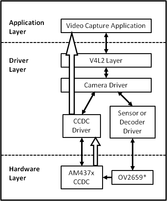
Capture Driver Component Overview
- Camera Applications
- Camera applications refer to any application that accesses the device node that is served by the Camera Driver. These applications are not in the scope of this design. They are here to present the environment in which the Camera Driver is used.
- V4L2 Subsystem
- The Linux V4L2 subsystem is used as an infrastructure to support the operation of the Camera Driver. Camera applications mainly use the V4L2 API to access the Camera Driver functionality. A Linux V4L2 implementation is used in order to support the standard features that are defined in the V4L2 specification.
- Videobuf2 Library
- This library is part of the V4L2 Layer. It provides helper functions to cleanly manage the video buffers through a video buffer queue object.
- Camera Driver
- The Camera Driver allows capturing video through an external sensor/decoder. It is a V4L2-compliant driver which provide access to the AM437x VPFE hardware feature. This driver conforms to the Linux driver model for power management. The camera driver is registered to the V4L2 layer as a master device driver. Any slave sensor/decoder driver added to the V4L2 layer will be attached to this driver through the new V4L2 sub-device interface layer. The current implementation supports only one slave device.
- Sensor/Decoder Driver
- The Camera Driver is designed to be AM437x VPFE module dependent, but platform and board independent. It is the sensor/decoder driver that manages the board connectivity. A decoder driver must implement the V4L2 sub-device interface. It should register to the V4L2 layer as a sub-device. Changing a sensor/decoder requires implementation of a new driver; it does not require changing the Camera Driver. Each sensor/decoder driver exports a set of IOCTLs to the master device through function pointers.
- CCDC library
- CCDC is a HW block, where it acts as a data input/entry port. It receives data from the sensor/decoder through parallel interface. The CCDC library exports API to configure CCDC module. It is configured by the master driver based on the sensor/decoder attached and desired output from the camera driver.
Source Location
- drivers/media/platform/ti_vpfe/
- AM437x VPFE Driver Sources
Kernel Configuration Options
The driver can be built as a static or dynamic module. When built as a dynamic module the driver is named ti_vpfe.ko.
By default VPFE support is built in to the 3.12 kernel when using omap2plus_defconfig.
$ make menuconfig ARCH=arm
- Select “Device Drivers” from the main menu.
...
...
Kernel Features  --->
Boot options  --->
CPU Power Management  --->
Floating point emulation  --->
Userspace binary formats  --->
Power management options  --->
[*] Networking support  --->
Device Drivers  --->
...
...
- Select “Multimedia support” from the menu and enter it.
...
...
[ ] ARM Versatile Express platform infrastructure
-*- Voltage and Current Regulator Support  --->
<*> Multimedia support  --->
    Graphics support  --->
<*> Sound card support  --->
    HID Devices  --->
[*] USB support  --->
...
...
- Select “V4L platform devices” from the menu.
--- Multimedia support
...
...
[ ]   Media PCI Adapters  ----
[*]   V4L platform devices -->
[ ]   Memory-memory multimedia devices ...
[ ]   Media test drivers  ----
      *** Supported MMC/SDIO adapters ***
< >   Cypress firmware helper routines
      *** Media ancillary drivers (tuners, sensors, i2c, frontends) ***
[ ]   Autoselect ancillary drivers (tuners, sensors, i2c, frontends)
      Encoders, decoders, sensors and other helper chips  --->
      Sensors used on soc_camera driver  ----
...
...
- Select “TI AM437x VPFE video capture driver” from the menu.
--- V4L platform devices
...
...
< > SoC camera support
<*>   TI AM437x VPFE video capture driver
...
...
- Selection of OV2659 Camera Sensor driver -
- Now go back to the Multimedia support level
De-select option Autoselect pertinent encoders/decoders and other helper chips and go inside Encoders/decoders and other helper chips
--- Multimedia support
...
...
[ ]   Autoselect ancillary drivers (tuners, sensors, i2c, frontends)
      Encoders, decoders, sensors and other helper chips  --->
      Sensors used on soc_camera driver  ----
...
...
- Select “OmniVision OV2659 sensor support” from the menu.
    *** Audio decoders, processors and mixers ***
...
...
< > Texas Instruments THS8200 video encoder
    *** Camera sensor devices ***
<*> OmniVision OV2659 sensor support
< > OmniVision OV7640 sensor support
...
...
Building as Loadable Kernel Module
- If you want to build the driver as a module, use <M> instead of <*> during menuconfig while selecting the drivers (as shown above). For more information on loadable modules refer Loadable Module HOWTO
DT Configuration
Example configuration in your board DTS file to enable VPFE instance 0. This an excerpt from the arch/arm/boot/dts/am437x-gp-evm.dts
&am43xx_pinmux {
       pinctrl-names = "default";
       pinctrl-0 = <&clkout2_pin &ddr3_vtt_toggle_default>;
...
...
       vpfe0_pins_default: vpfe0_pins_default {
               pinctrl-single,pins = <
                       0x1B0 (PIN_INPUT_PULLUP | MUX_MODE0)  /* cam0_hd mode 0*/
                       0x1B4 (PIN_INPUT_PULLUP | MUX_MODE0)  /* cam0_vd mode 0*/
                       0x1B8 (PIN_INPUT_PULLUP | MUX_MODE0)  /* cam0_field mode 0*/
                       0x1BC (PIN_INPUT_PULLUP | MUX_MODE0)  /* cam0_wen mode 0*/
                       0x1C0 (PIN_INPUT_PULLUP | MUX_MODE0)  /* cam0_pclk mode 0*/
                       0x1C4 (PIN_INPUT_PULLUP | MUX_MODE0)  /* cam0_data8 mode 0*/
                       0x1C8 (PIN_INPUT_PULLUP | MUX_MODE0)  /* cam0_data9 mode 0*/
                       0x208 (PIN_INPUT_PULLUP | MUX_MODE0)  /* cam0_data0 mode 0*/
                       0x20C (PIN_INPUT_PULLUP | MUX_MODE0)  /* cam0_data1 mode 0*/
                       0x210 (PIN_INPUT_PULLUP | MUX_MODE0)  /* cam0_data2 mode 0*/
                       0x214 (PIN_INPUT_PULLUP | MUX_MODE0)  /* cam0_data3 mode 0*/
                       0x218 (PIN_INPUT_PULLUP | MUX_MODE0)  /* cam0_data4 mode 0*/
                       0x21C (PIN_INPUT_PULLUP | MUX_MODE0)  /* cam0_data5 mode 0*/
                       0x220 (PIN_INPUT_PULLUP | MUX_MODE0)  /* cam0_data6 mode 0*/
                       0x224 (PIN_INPUT_PULLUP | MUX_MODE0)  /* cam0_data7 mode 0*/
               >;
       };


       vpfe0_pins_sleep: vpfe0_pins_sleep {
               pinctrl-single,pins = <
                       0x1B0 (DS0_PULL_UP_DOWN_EN | INPUT_EN | MUX_MODE7)  /* cam0_hd mode 0*/
                       0x1B4 (DS0_PULL_UP_DOWN_EN | INPUT_EN | MUX_MODE7)  /* cam0_vd mode 0*/
                       0x1B8 (DS0_PULL_UP_DOWN_EN | INPUT_EN | MUX_MODE7)  /* cam0_field mode 0*/
                       0x1BC (DS0_PULL_UP_DOWN_EN | INPUT_EN | MUX_MODE7)  /* cam0_wen mode 0*/
                       0x1C0 (DS0_PULL_UP_DOWN_EN | INPUT_EN | MUX_MODE7)  /* cam0_pclk mode 0*/
                       0x1C4 (DS0_PULL_UP_DOWN_EN | INPUT_EN | MUX_MODE7)  /* cam0_data8 mode 0*/
                       0x1C8 (DS0_PULL_UP_DOWN_EN | INPUT_EN | MUX_MODE7)  /* cam0_data9 mode 0*/
                       0x208 (DS0_PULL_UP_DOWN_EN | INPUT_EN | MUX_MODE7)  /* cam0_data0 mode 0*/
                       0x20C (DS0_PULL_UP_DOWN_EN | INPUT_EN | MUX_MODE7)  /* cam0_data1 mode 0*/
                       0x210 (DS0_PULL_UP_DOWN_EN | INPUT_EN | MUX_MODE7)  /* cam0_data2 mode 0*/
                       0x214 (DS0_PULL_UP_DOWN_EN | INPUT_EN | MUX_MODE7)  /* cam0_data3 mode 0*/
                       0x218 (DS0_PULL_UP_DOWN_EN | INPUT_EN | MUX_MODE7)  /* cam0_data4 mode 0*/
                       0x21C (DS0_PULL_UP_DOWN_EN | INPUT_EN | MUX_MODE7)  /* cam0_data5 mode 0*/
                       0x220 (DS0_PULL_UP_DOWN_EN | INPUT_EN | MUX_MODE7)  /* cam0_data6 mode 0*/
                       0x224 (DS0_PULL_UP_DOWN_EN | INPUT_EN | MUX_MODE7)  /* cam0_data7 mode 0*/
               >;
       };
...
...
};
...
...
&i2c1 {
       status = "okay";
       pinctrl-names = "default";
       pinctrl-0 = <&i2c1_pins>;
...
...
       ov2659@30 {
               compatible = "ti,ov2659";
               reg = <0x30>;


               port {
                       ov2659_0: endpoint {
                               remote-endpoint = <&vpfe0_ep>;
                               mclk-frequency = <12000000>;
                       };
               };
       };
};
...
...
&vpfe0 {
       status = "okay";
       pinctrl-names = "default", "sleep";
       pinctrl-0 = <&vpfe0_pins_default>;
       pinctrl-1 = <&vpfe0_pins_sleep>;


       /* Camera port \*/
       port {
               vpfe0_ep: endpoint {
                       remote-endpoint = <&ov2659_0>;
                       if_type = <2>;
                       bus_width = <8>;
                       hdpol = <0>;
                       vdpol = <0>;
               };
       };
};
- remote-endpoint is a reference to the i2c sensor node. This is used during sub-device registration.
- if-type defines the interface type used <0> BT656, <2> RAW.
- bus_width defines the number of data pins actually connected between the camera and the vpfe module. Only 2 values are supported 8 and 10. Pre-Beta boards had 10 data pins connected, Beta (and later) have 8 data pins connected which is a hardware level optimization reducing memory bus bandwidth and eliminating post-processing to compact the captured data.
- hdpol when set to 1 is used to invert the Hsync polarity
- vdpol when set to 1 is used to invert the Vsync polarity
Driver Usage
As seen previously the driver create a /dev/videoX device node when a sub-device is successfully registered. The device node provide access to the driver following a standard V4L2 API.
The driver support the following system calls and V4L2 ioctls:
open(), close(), mmap(), munmap() and ioctl()
| V4L2 ioctls | Definition |
|---|---|
| VIDIOC_REQBUFS | Allocating Memory Buffers |
| VIDIOC_QUERYBUF | Getting Buffer’s Physical Address |
| VIDIOC_QUERYCAP | Query Capabilities |
| VIDIOC_ENUMINPUT | Input Enumeration |
| VIDIOC_S_INPUT | Set Input |
| VIDIOC_G_INPUT | Get Input |
| VIDIOC_ENUMSTD | Standard Enumeration |
| VIDIOC_QUERYSTD | Query Standard |
| VIDIOC_S_STD | Set Standard |
| VIDIOC_G_STD | Get Standard |
| VIDIOC_ENUM_FMT | Format Enumeration |
| VIDIOC_ENUM_FRAMESIZES | Frame Size Enumeration |
| VIDIOC_S_FMT | Set Format |
| VIDIOC_G_FMT | Get Format |
| VIDIOC_TRY_FMT | Try Format |
| VIDIOC_QUERYCTRL | Query Control* |
| VIDIOC_S_CTRL | Set Control* |
| VIDIOC_G_CTRL | Get Control* |
| VIDIOC_QBUF | Queue Buffer |
| VIDIOC_DQBUF | Dequeue Buffer |
| VIDIOC_STREAMON | Stream On |
| VIDIOC_STREAMOFF | Stream Off |
| VIDIOC_CROPCAP | Query Cropping Capabilities+ |
| VIDIOC_S_CROP | Set Crop Parameters+ |
| VIDIOC_G_CROP | Get Current Cropping Parameters+ |
Table: Supported ioctls
There are plenty of generic V4L2 capture applications available:
There is also a media controller sample application which can be used as an example to configured sensor/decoder sub-device:
Debugging
As vpfe driver is based on the V4L2 framework, framework level tracing can be enable as follows:
- echo 3 >/sys/class/video4linux/video1/dev_debug This allows V4L2 ioctl calls to be logged.
- echo 3 > /sys/module/videobuf2_core/parameters/debug This allows VB2 buffers operation to be logged.
In addition vpfe also has specific debug log which can be enabled as follows:
- echo 3 > /sys/module/am437x_vpfe/parameters/debug
3.3.4.4. VIP
Introduction
This page gives a basic description of Video Input Port (VIP) hardware, the Linux kernel driver (ti-vip) and various TI boards which uses VIP. The technical reference manual (TRM) for the SoC in question, and the board documentation give more detailed descriptions.
Release Applicable
This page applies to TI’s v4.4 kernel. Although most of it is also applicable to TI’s v4.1 and v3.14 kernel.
Supported Devices
The VIP IP is only available on the following TI SoCs or SoC families:
- AM5x
- DRA7x
Hardware Architecture
On supported SoCs the Video Input Port (VIP) module is used for video capture from video encoder/decoder and camera sensor.
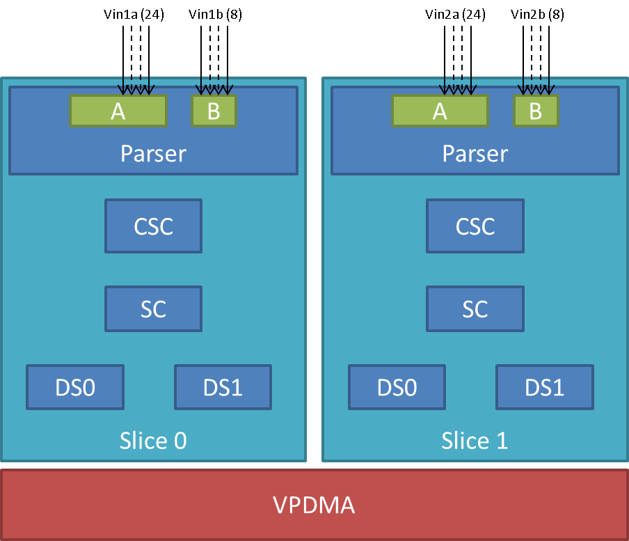
VIP Instance block diagram
VIP instance has two slices each having one 24/16/8 bit port and one 8 bit video port. Each slice has a color space converter block, a scaler block and a pair of down-sampler block. A common VPDMA block is used for writing frames to memory. VIP Parser supports video capture from discrete sync / embedded sync, YUV / RGB format video sources. It calculates the frame size based on the count of clocks in hsyncs(width) and count of hsyncs in vsyncs(height). The complex data path configurability allows to have up to four parallel ports captures from one instance. One port per slice can utilize the inline CSC and/or SC block at a time. VPDMA block has a TI proprietary custom programmable processor. A custom firmware is needed for this custom processor. VPDMA programming is descriptor based. It allows to setup, configure, control, abort DMA transactions from different channels to and from memory. VPDMA needs physically contiguous buffers for capture. It also supports addressing in the TILER space.
SoC Hardware Feature
- AM572x/DRA74x/DRA75x
- VIP1 and VIP2 instance each supporting up to
- Two separate 24-bit video ports for parallel RGB/YUV/RAW (or BT656/1120) data, up to 165 MHz
- Two separate 8-bit video ports for YUV/RAW (or BT656) data, up to 165 MHz
- VIP3 instance supporting up to
- Two separate 16-bit video ports for parallel RGB/YUV/RAW (or BT656/1120) data, up to 165 MHz
- VIP1 and VIP2 instance each supporting up to
- AM571x/DRA72x
- VIP1 instance supporting up to
- Two separate 24-bit video ports for parallel RGB/YUV/RAW (or BT656/1120) data, up to 165 MHz
- Two separate 8-bit video ports for YUV/RAW (or BT656) data, up to 165 MHz
- VIP1 instance supporting up to
Driver Architecture
Linux kernel driver for the VIP is implemented as per the V4L2 standard for capture devices. VIP driver is responsible only for the programming of the VIP device. For programming external video devices, we need a V4L2 subdevice driver which is used in conjunction with the V4L2 driver. It also uses some of the helper kernel libraries videobuf2 (VB2) for common buffer operations, queue management and memory management.
- Linux Media Subsystem Documentation
- Video for Linux API
- V4L2 videobuf2 functions and data structures
- V4L2 sub-devices
V4L2 endpoint device tree bindings
Different camera / video sources have different configuration parameters when interfacing with the VIP video ports. Common interfacing properties like Hsync, Vsync, Pclk polarities can be different across different devices. V4L2 endpoint allows to describe these as part of device tree definition. This makes the VIP driver generic enough to have no dependency on the camera device. It also provides the flexibility to work with new cameras by doing simple device tree modifications.
Following is an example showcasing the DT entries of VIP device node and its usage when interfacing different video sources.
| VIP device definition | Camera device definition |
|---|---|
vip1 {
    #address-cells = <1>;
    #size-cells = <0>;
    status = "okay";
    ports {
        vin1a: port@0 {
             reg = <0>;
             #address-cells = <1>;

             #size-cells = <0>;
             status = "okay";
             endpoint@0 {
                 remote-endpoint = <&cam1>;

             };
        };
        ...
        vin2a: port@2 {
             ...
             reg = <2>;
        };
        ...
    };
};
|
ov10633@37 {
    compatible = "ovti,ov10633";
    reg = <0x37>
    ...
    port {
        cam1: endpoint {
            remote-endpoint = <&vin1a>;
            hsync-active = <1>;
            vsync-active = <1>;
            pclk-sample = <0>;

        };
    };
};
|
V4L2 asynchronous subdevice registration
Each camera device that VIP driver communicates to is modelled as a V4L2 subdevice. In the probe sequence, VIP and camera drivers are probed at different time. V4L2 async subdevice binding helps to bind the VIP device and the camera device together. VIP driver looks for the camera entries in the endpoints and registers (v4l2_async_notifier_register) a callback if any of the requested devices become available. vip_async_bound implements the priority based binding which allows to have multiple cameras muxed against same video port. The device tree order determines which of these gets picked up by the driver. Note that the V4L2 g/s_input ioctls are not supported, userspace won’t be able to select specific camera with these ioctls.
Of course the target subdevice driver also needs to support the asynchronous registration framework. On top of this the subdevice driver must implements the following ioctls for the handshake with the VIP driver to work properly:
- get_fmt()
- set_fmt()
- enum_mbus_code()
- enum_frame_sizes()
- s_stream()
Driver Features
Note: this is not a comprehensive list of features supported/not supported.
Supported Features
- VIP input Pixel formats
- Sub device is expected to support one of the below format. Only YUV422 interleaved format arranged as UYVY is supported in YUV mode. This restrictions in pixel arrangements is to take care of silicon errata i839 guidelines.
- The data formats mentioned in parenthesis in below table is in
V4L2 Media Bus Format.
- For instance, a format where pixels are encoded as 8-bit YUV values downsampled to 4:2:2 and transferred as 2 8-bit bus samples per pixel in the U, Y, V, Y order is named as MEDIA_BUS_FMT_UYVY8_2X8.
- The data bus width can be 8 bit or 16 bit wide when capturing in
UYVY mode.
- Default bus width configuration is 8 bit. When using 16 bit wide bus, specify the bus width in dts file as bus-width = <16>;
| YUV | RGB | RAW Bayer 8-bit |
|---|---|---|
| UYVY (UVYV8_2x8) | RGB24 (RGB888_1X24) | BGGR8 (SBGGR8_1X8) |
| RGB32 (ARGB8888_1X32) | GBRG8 (SGBRG8_1X8) | |
| GRBG8 (SGRBG8_1X8) | ||
| RGGB8 (SRGGB8_1X8) |
Table: Supported Input Pixel Format in FOURCC and V4L2 MEDIA_BUS_FMT
- Supported VIP output pixel formats
- Runtime pixel format availability is based on the sub-device capability. Use yavta –enum-formats /dev/video1 to get an accurate list.
| YUV | RGB | RAW Bayer 8-bit |
|---|---|---|
| NV12 | RGB3 | BA81 |
| YUYV | BGR3 | GBRG |
| UYVY | RGB4 | GRBG |
| VYUY | BGR4 | RGGB |
| YVYU |
Table: Supported Output Pixel Format
- Scaling (only available with YUV format)
- Down-scaling only (will use the closest native resolution larger than the desired frame size)
- Down-scaling ratio limitations -
- Horizontal - up to 1/8th
- Vertical - up to 3/16
- Color Space Conversion
- YUV to RGB (tested)
- RGB to YUV (untested)
- V4L2 single-planar buffers and interface
- Supports MMAP buffers (allocated by kernel from global CMA pool) and also allows to export them as DMABUF
- Supports DMABUF import (Reusing buffers from other drivers)
- Discrete Sync capture
- Embedded Sync capture in 8-bit mode
- Multi-channel capture when using embedded sync
Unsupported Features/Limitations By VIP Driver
- Media Controller Framework
- Cropping/Selection ioctls
- TILER memory space
- 16 bit embedded capture
- 16 bit RAW capture
- YUV444 Input format
- YUV444 mode is similar to RGB24 mode. Driver can be modified to enable YUV44 mode by referring to the RGB24 settings in vip.c file
- Input format capture for YUV422 mode in arrangements other than UYVY
- Refer to the settings of Raw Bayer input format in vip.c file to enable other YUV input mode capture
- Maximum capture resolution restricted to 2048x1536
- HSYNC and Discrete Basic Mode set as 1 are hard coded in the driver and not controlled through dts entries. VIP driver register settings will need changes if the signals used for capture are DE (ACTVID) and/or Discrete Basic Mode set as 0.
Hardware Limitations
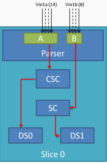
VIP Slice
- CSC, SC and/or DS processing in discrete sync mode is supported only
for following combination -
- Input as RGB or UYVY format and output in supported YUV format
- CSC, SC and/or DS processing is not supported for embedded sync input in multiplexed source mode
- CSC and SC can not be used simultaneously by port A and port B of a Slice. For example, if port A is using CSC, then port B can only use SC but not CSC
- Maximum input resolution when using SC is 2047x2047 pixels (irrespective of pixel size).
- Maximum capture width when not using scaling is 8K bytes. This
translates to maximum frame width of -
- 4K when capturing in YUV422 mode (2 bytes/pixel)
- 2.2K when capturing in RGB24 mode (3 bytes/pixel)
- 8K when capturing as Raw Bayer 8-bit or other format treated as 1 bytes/pixel
- No restrictions on height of capture video
Driver Configuration
Kernel Configuration Options
ti-vip supports building both as built-in or as a module.
ti-vip can be found under “Device Drivers/Multimedia support/V4L platform devices” in the kernel menuconfig. You need to enable V4L2 (CONFIG_MEDIA_SUPPORT, CONFIG_MEDIA_CAMERA_SUPPORT) and then enable V4L platform driver (CONFIG_V4L_PLATFORM_DRIVERS) before you can enable ti-vip (CONFIG_VIDEO_TI_VIP).
Driver Usage
Loading ti-vip
If built as a module, you need to load all the v4l2-common, videobuf2-core and videobuf2-dma-contig modules before ti-vip will start.
Using ti-vip
When ti-vip is enabled, the capture device will appear as /dev/videoX. Standard V4L2 user space applications can be used as long as the capability of the application matches.
- dmabuftest example Use VIP to capture a 1280x800 YUYV video stream and display it on an HDMI display using DMABUF buffers.
dmabuftest -s 36:1920x1080 -c 1280x800@YUYV -d /dev/video1
- yavta example Capture 800x600 YUYV video stream to file.
yavta -c60 -fYUYV -Fvout_800x600_yuyv.yuv -s800x600 /dev/video1
dmabuftest can be found from:
https://git.ti.com/glsdk/omapdrmtest
yavta can be found from:
http://git.ideasonboard.org/yavta.git
Debugging
As ti-vip driver is based on the V4L2 framework, framework level tracing can be enable as follows:
- echo 3 >/sys/class/video4linux/video1/dev_debug This allows V4L2 ioctl calls to be logged.
- echo 3 > /sys/module/videobuf2_core/parameters/debug This allows VB2 buffers operation to be logged.
In addition ti-vip also has specific debug log which can be enabled as follows:
- echo 3 > /sys/module/ti_vip/parameters/debug
Troubleshooting common capture problem
Bootup/Probe checks
First thing to look for is if the video devices are created or not; Check the bootlog for prints in the kernel bootlog.
Check device probe status
dmesg | grep ov1063x
dmesg | grep video
Depending on the camera connected, the following prints can confirm the probe being successful.
| Bootlog print | Result |
|---|---|
| ov1063x 1-0037: ov1063x Product ID a6 Manufacturer ID 33 | Onboard camera probe success |
| ov1063x X-00XX: Failed writing register 0x0103! | Camera not connected |
No video captured
When the capture application is launched, it is expected to start video capture and display frames on to display. Sometimes, no video is not displayed on the screen. To identify this being an issue with capture, simple test can be done. Each VIP slice has a dedicated interrupt line. If the capture is successful, the interrupt count should increase periodically.
Check interrupts to confirm capture failure
cat /proc/interrupts | grep vip
362:        941          0       GIC 102  vip1-s0
363:        183          0       GIC 101  vip1-s1
364:        241          0       GIC 100  vip2-s0
365:          0          0       GIC  99  vip2-s1
366:         46          0       GIC  98  vip3-s0
367:          2          0       GIC  97  vip3-s1
In the above example, one can conclude that
- Capture from Vin1, Vin2, Vin3, Vin5 is working fine.
- Vin4(vip2-s1) capture was never attempted.
- Vin6(vip3-s1) capture is failing (Note that first two interrupts occur even if the camera isn’t connected. Refer VPDMA fifo)
Note that the IRQs are shared for different ports of same slice. This means, vip1-s0 line will carry interrupts from both vin1a and vin1b. This test can be used when only one of the port is in use.
VIP Parser is not able to detect the video
| Video Port | Parser size register | Parser config register |
|---|---|---|
| vin1a | 0x48975530 | 0x48975504 |
| vin1b | 0x48975570 | 0x4897550C |
| vin2a | 0x48975A30 | 0x48975A04 |
| vin2b | 0x48975A70 | 0x48975A0C |
| vin3a | 0x48995530 | 0x48995504 |
| vin3b | 0x48995570 | 0x4899550C |
| vin4a | 0x48995A30 | 0x48995A04 |
| vin4b | 0x48995A70 | 0x48995A0C |
| vin5a | 0x489B5530 | 0x489B5504 |
| vin6a | 0x489B5A30 | 0x489B5A0C |
Invalid parser configuration
Depending on the camera used, certain parameters of the video port needs to be configured correctly. Device tree definition (endpoint nodes) is used for specifying these parameters.
| Usecase | Required parameters |
|---|---|
| Parallel port | Bus width (8/16bit for YUV, 24bit for RGB) |
| Descrete sync | hsync, vsync, pclk polarities |
| Embedded sync | Multiplexing method, channel numbers |
To check if the correct parameters are being passed or not, procfs can be used for checking values of some of the properties on target.
Using procfs to read DT params
cat /proc/device-tree/ocp/i2c@480720000/ov10635@37/compatible
hexdump -b /proc/device-tree/ocp/i2c@480720000/ov10635@37/port/endpoint@0/pclk-sample
hexdump -b /proc/device-tree/ocp/i2c@480720000/ov10635@37/port/endpoint@0/bus-width
hexdump -b /proc/device-tree/ocp/i2c@480720000/ov10635@37/port/endpoint@0/channels
Note that some of the integer properties are not printable in ASCII format. Using hexdump gives readability to read integer values from device tree.
Camera isn’t started, pclk, syncs are dead
Video is being captured but image is pixelated or distorted
FAQ
Can VIP be used as high speed interface to bring any data in?
VIP can be used as high speed interface to bring any data as is (without any modifications) into the device. Following points to keep in mind –
- Data should be sent in discrete sync mode.
- No other VIP internal processing blocks like color space conversion, scaling or chroma format conversion should be used.
- Refer to Driver_Features section if there is need to bring data in resolution greater than the one supported by driver.
- If the cropping feature is disabled in VIP parser due to the need for capturing larger resolution and if interested in capturing last frame (that could be only frame), FPGA need to send additional VSYNC signal else the last frame will not get transferred to DDR.
- Add vip_fmt entry in the vip_formats table inside drivers/media/platform/ti-vpe/vip.c per sub-device driver need for ”.fourcc”, ”.code” and ”.colorspace”. Keep ”.coplanar” as 0. Refer to the entries of VPDMA_DATA_FMT_RAW8 in drivers/media/platform/ti-vpe/vpdma.c file for “vpdma_fmt” settings when using VIP slice in 8 bit port mode. Refer to the VPDMA_DATA_FMT_RAW16 format settings for 16 bit mode. Note that VIP driver supports only 8 bit RAW mode. Enabling 16 bit RAW mode capture needs minor driver modifications. If custom entries are not needed, then any of the raw format entries can be used. In that case, sensor driver will need to configure media bus format as ”.code” settings as shown in the vip_fmt.
static struct vip_fmt vip_formats[VIP_MAX_ACTIVE_FMT] = {
    {
        .fourcc        = V4L2_PIX_FMT_SBGGR8,
        .code      = MEDIA_BUS_FMT_SBGGR8_1X8,
        .colorspace    = V4L2_COLORSPACE_SMPTE170M,
        .coplanar  = 0,
        .vpdma_fmt = { &vpdma_raw_fmts[VPDMA_DATA_FMT_RAW8],
                  },
    },

const struct vpdma_data_format vpdma_raw_fmts[] = {
    [VPDMA_DATA_FMT_RAW8] = {
        .type      = VPDMA_DATA_FMT_TYPE_YUV,
        .data_type = DATA_TYPE_CBY422,
        .depth     = 8,
    },
What’s the maximum frame rate possible for W*H resolution using VIP?
As mentioned in Hardware_Architecture section, each slice in VIP instance has one 24/16/8 bit port through which data can come in. Each video port can be clocked up to 165 MHz. Assuming 27% left spare for horizontal and vertical blanking, roughly 120 MHz left for actual data. If VIP Slice is configured in 8 bit port mode, then 1 bytes can be brought in per clock cycle. In 8 bit port mode and with 120 MHz clock for data capture, maximum possible capture rate is 120 Mbytes/sec, in 16 bit port mode it will be 240 Mbytes/sec and in 24 bit port mode it will be 360 Mbytes/sec. Now for X*Y resolution, maximum possible frame rate can be calculated using following formula –
FPS = 120 * 1000000 * port_mode/(frame_resolution * num_bytes_per_pixel)
In above formula -
- port_mode can take value of 1 for 8 bit, 2 for 16 bit and 3 for 24 bit port mode configuration.
- Frame_resolution is product of width and height of frame.
- num_bytes_per_pixel is number of bytes per pixel. For example, if capturing in YUYV format it’s value is 2, when capturing in RGB24 format, it’s value is 3.
What is the maximum frame resolution that can be captured using VIP?
Refer to Hardware_Limitations section to understand maximum possible resolution supported by VIP IP. Refer to Unsupported_Features/Limitations section to understand the resolution supported by VIP driver. Driver changes will be needed to capture the resolution beyond the one supported by the driver but within VIP IP limits. Below are suggested modifications inside driver. There may be more changes needed.
- Change MAX_W and MAX_H in vip.c file per the desired capture resolution.
- Disable hardware enabled cropping feature inside the driver if the
desired resolution width is greater than 4K pixels (not bytes) and/or
height is greater than 4K lines.
- To disable cropping, comment the function call to vip_set_crop_parser() function inside vip_setup_parser() function defined in drivers/media/platform/ti-vpe/vip.c file
Why I am not seeing any interrupt generated from the sensor?
Not getting any interrupts usually means the module is not receiving/detecting video data. To proceed with debugging, probe the pclk, vysnc and hsync signal at the connector. If they look as what you are expecting, then verify the pinmux.
How do I capture 10-bit or 12-bit YUV data?
VIP can capture data in 8, 16 or 24 bus-width size. Configure VIP for 16 bit bus-width size in order to capture pixel of 10-bit or 12-bit size. This includes dts file configuration and pin-mux configuration. Connect the pixel size data lanes from the sensor board to VIP input port. Ground or tie to VDD remaining unused pins. VIP will receive the 10-bit/12-bit data in 16-bit container in memory with 6/4 LSb or MSb bit always being low or high based on how those unused bits are tied. Note that when capturing 10-bit/12-bit data in 16 bit container, you can not use any of the VIP internal processing module like scaling, format conversion etc.
In dts file, specify the bus-width field as 16
bus-width = <16>; /* Used data lines */
TI Board Specific Information
None at this time.
3.3.4.5. Crypto
Introduction
The Crypto API Driver is a set of Linux drivers that provide access to the hardware cryptographic accelerators available on AM335x/AM437x/AM57x/DRA7 devices. These drivers are available built-in in the kernel in the current SDK release.
Following are the Hardware accelerators supported on the following devices:
* AM335X     : MD5, SHA1, SHA224, SHA256, AES, DES
* AM437X     : MD5, SHA1, SAH224, SHA256, SHA384, SHA512, AES, DES, DES3DES
* AM57x/DRA7 : AES, DES, DES3DES
Building the Driver
For devices with available cryptographic hardware accelerators, a Linux driver and additionally an Cryptodev (or OCF on AMSDK v6.0 or older) kernel module (for OpenSSL) is needed to access them. Other devices use the pure software implementation of OpenSSL for the crypto demos.
AM335x, AM43xx - AES, DES, SHA/MD5 Drivers
Starting with AMSDK 5.05.00.00, the driver is completely integrated into the kernel source. The pre-built kernel that comes with the SDK already has the AES, DES and SHA/MD5 drivers built-in to the kernel. The kernel configuration has already been set up in the SDK and no further configuration is needed for the drivers to be built-in to the kernel. The configuration of the random number generator does require an extra step and this is detailed in the next section.
For reference, the configuration details are shown below. The configuration of the AES, DES and SHA/MD5 driver is done under the Hardware crypto devices sub-menu of the Cryptographic API menu in the kernel configuration.
--- Cryptographic API
    [*] Hardware crypto devices --->
        --- Hardware crypto devices
            <*> Support for OMAP MD5/SHA1/SHA2 hw accelerator
            <*> Support for OMAP AES hw engine
            <*> Support for OMAP DES3DES hw engine
Messages printed during bootup will indicate that initialization of the crypto modules has taken place.
[    2.120565] omap-sham 53100000.sham: hw accel on OMAP rev 4.3
[    2.160584] mmc1: BKOPS_EN bit is not set
[    2.173466] omap-aes 53500000.aes: OMAP AES hw accel rev: 3.2
[    2.180241] edma-dma-engine edma-dma-engine.0: allocated channel for 0:5
[    2.187808] edma-dma-engine edma-dma-engine.0: allocated channel for 0:6
Build the Cryptodev kernel module using SDK
For using OpenSSL to access the Crypto Hardware Accelerator Drivers above, the Cryptodev is required (can be built as module). The framework is not officially in the kernel and was ported to Linux under the name “cryptodev”.
Using Cryptographic Hardware Accelerators
Using the TRNG Hardware Accelerator
The pre built kernel that come with the SDK already has the TRNG driver built into the kernel. No further configuration is required.
For reference, the configuration details are shown below.
In the configuration menu, scroll down to Device Drivers and hit enter. Now scroll to Character devices and hit enter.
Device Drivers --->
   Character devices --->
       < > Hardware Random Number Generator Core support
           < > OMAP Random Number Generator support
[ 1.660514] omap_rng 48310000.rng: OMAP Random Number Generator ver. 20
root@am335x-evm:~# ls -l /dev/hwrng
crw------- 1 root root 10, 183 Jan 1 2000 /dev/hwrng
root@am335x-evm:~#
root@am335x-evm:~# cat /dev/hwrng | od -x
0000000 b2bd ae08 4477 be48 4836 bf64 5d92 01c9
0000020 0cb6 7ac5 16f9 8616 a483 7dfd 6bf4 3aa5
0000040 d693 db24 d917 5ee7 feb7 34c3 34e9 e7a5
0000060 36b7 ea85 fc17 0e66 555c 0934 7a0c 4c69
0000100 523b 9f21 1546 fddb d58b e5ed 142a 6712
0000120 8d76 8f80 a6d2 30d8 d107 32bc 7f45 f997
0000140 9d5d 0d0c f1f0 64f9 a77f 408f b0c1 f5a0
0000160 39c6 f0ae 4b59 1a76 84a7 a364 8964 f557
root@am335x-evm:~#
Support tools for the hardware random number generator can be loaded from rng-tools on Sourceforge. The latest version at the time of this write-up is version 3.0, dated 2010-07-04.
1. We’re still in the Linux-devkit environment. Download the file rng-tools-3.tar.gz, and untar in a suitable location.
2. Change to the directory that contains the rng-tools distribution, and configure the package:
host $ ./configure --prefix=/home/user/targetfs/TI814x-targetfs_5_03_01/usr \
 --exec-prefix=/home/user/targetfs/TI814x-targetfs_5_03_01/usr \
 --host --target=arm-linux
3. Next make the rngd and rngtest executables.
host $ make
4. Install the generated executables in the target filesystem.
5. Test the random number generator on the target.
root@am335x-evm:~# cat /dev/hwrng | rngtest -c 1000
rngtest 3
Copyright (c) 2004 by Henrique de Moraes Holschuh
This is free software; see the source for copying conditions.  There is NO warranty; not even for MERCHANTABILITY or FITNESS FOR A PARTICULAR PURPOSE.

rngtest: starting FIPS tests...
rngtest: bits received from input: 20000032
rngtest: FIPS 140-2 successes: 999
rngtest: FIPS 140-2 failures: 1
rngtest: FIPS 140-2(2001-10-10) Monobit: 0
rngtest: FIPS 140-2(2001-10-10) Poker: 0
rngtest: FIPS 140-2(2001-10-10) Runs: 1
rngtest: FIPS 140-2(2001-10-10) Long run: 0
rngtest: FIPS 140-2(2001-10-10) Continuous run: 0
rngtest: input channel speed: (min=788.218; avg=4070.983; max=2790178.571)Kibits/s
rngtest: FIPS tests speed: (min=846.755; avg=15388.376; max=21920.595)Kibits/s
rngtest: Program run time: 6072670 microseconds
Note that the results may be slightly different on your system, since, after all, we’re dealing with a random number generator. Any appreciable number of errors typically indicates a bad random number generator.
If you’re satisfied the random number generator is working correctly, you can use rngd (the random number generator daemon) to feed the /dev/random entropy pool.
AES, DES, SHA Hardware Accelerators using Cryptodev
The device drivers for AES, DES and SHA/MD5 hardware acceleration is configured and built into the kernel by default. No other special setup is needed for OpenSSL to access the crypto modules.
First, the kernel from the SDK must be configured and built according to the SDK User’s Guide.
The General Purpose (GP) EVMs on TI SoCs allows access to built in cryptographic accelerators. Inorder to use these drivers from OpenSSL, the drivers on their own have no contact with userspace. For this, a special driver is available which abstracts the access to these accelerators through Cryprodev module.
The demo application under the crypto menu of Matrix will load and use the Cryptodev driver kernel modules automatically to perform hardware accelerated crypto functions. The process of manually loading the kernel modules and using the driver is explained below.
Cryptodev is itself a special device driver which provides a general interface for higher level applications such as OpenSSL to access hardware accelerators.
The filesystem which comes with the SDK comes built with the Cryptodev kernel modules and the TI driver which directly accesses the hardware accelerators is built into the kernel.
From the target boards perspective the drivers are located in the following directories:
/lib/modules/`uname -r`/extra/cryptodev.ko
To use the drivers they must first be installed. Use the modprobe command to install the drivers. The following log shows the commands used to install the modules and query the system for the state of all system modules.
root@am335x-evm:~# lsmod
Module                  Size  Used by
cryptodev              11962  0
root@am335x-evm:~#
After the modules are installed, OpenSSL commands may be executed which take advantage of the hardware accelerators through the Cryptodev driver. The following example demonstrates the OpenSSL built-in speed test to demonstrate performance. The addition of the parameter -engine cryptodev tells OpenSSL to use the Cryptodev driver if it exists.
root@am335x-evm:~# openssl speed -evp aes-128-cbc -engine cryptodev
engine "cryptodev" set.
Doing aes-128-cbc for 3s on 16 size blocks: 108107 aes-128-cbc's in 0.16s
Doing aes-128-cbc for 3s on 64 size blocks: 103730 aes-128-cbc's in 0.20s
Doing aes-128-cbc for 3s on 256 size blocks: 15181 aes-128-cbc's in 0.03s
Doing aes-128-cbc for 3s on 1024 size blocks: 15879 aes-128-cbc's in 0.03s
Doing aes-128-cbc for 3s on 8192 size blocks: 4879 aes-128-cbc's in 0.02s
OpenSSL 1.0.0b 16 Nov 2010
built on: Thu Jan 20 10:23:44 CST 2011
options:bn(64,32) rc4(ptr,int) des(idx,risc1,2,long) aes(partial) idea(int) blowfish(idx)
compiler: arm-none-linux-gnueabi-gcc -march=armv7-a -mtune=cortex-a8 -mfpu=neon -mfloat-abi=softfp -mthumb-interwork -mno-thumb -fPS
The 'numbers' are in 1000s of bytes per second processed.
type 16 bytes 64 bytes 256 bytes 1024 bytes 8192 bytes
aes-128-cbc 10810.70k 33193.60k 129544.53k 542003.20k 1998438.40k
root@am335x-evm:~#
root@am335x-evm:~#
root@am335x-evm:~#
Using the Linux time -v function gives more information about CPU usage during the test.
root@am335x-evm:~# time -v openssl speed -evp aes-128-cbc -engine cryptodev
engine "cryptodev" set.
Doing aes-128-cbc for 3s on 16 size blocks: 108799 aes-128-cbc's in 0.17s
Doing aes-128-cbc for 3s on 64 size blocks: 102699 aes-128-cbc's in 0.18s
Doing aes-128-cbc for 3s on 256 size blocks: 16166 aes-128-cbc's in 0.03s
Doing aes-128-cbc for 3s on 1024 size blocks: 15080 aes-128-cbc's in 0.03s
Doing aes-128-cbc for 3s on 8192 size blocks: 4838 aes-128-cbc's in 0.03s
OpenSSL 1.0.0b 16 Nov 2010
built on: Thu Jan 20 10:23:44 CST 2011
options:bn(64,32) rc4(ptr,int) des(idx,risc1,2,long) aes(partial) idea(int) blowfish(idx)
compiler: arm-none-linux-gnueabi-gcc -march=armv7-a -mtune=cortex-a8 -mfpu=neon -mfloat-abi=softfp -mthumb-interwork -mno-thumb -fPS
The 'numbers' are in 1000s of bytes per second processed.
type 16 bytes 64 bytes 256 bytes 1024 bytes 8192 bytes
aes-128-cbc 10239.91k 36515.20k 137949.87k 514730.67k 1321096.53k
Command being timed: "openssl speed -evp aes-128-cbc -engine cryptodev"
User time (seconds): 0.46
System time (seconds): 5.89
Percent of CPU this job got: 42%
Elapsed (wall clock) time (h:mm:ss or m:ss): 0m 15.06s
Average shared text size (kbytes): 0
Average unshared data size (kbytes): 0
Average stack size (kbytes): 0
Average total size (kbytes): 0
Maximum resident set size (kbytes): 7104
Average resident set size (kbytes): 0
Major (requiring I/O) page faults: 0
Minor (reclaiming a frame) page faults: 479
Voluntary context switches: 36143
Involuntary context switches: 211570
Swaps: 0
File system inputs: 0
File system outputs: 0
Socket messages sent: 0
Socket messages received: 0
Signals delivered: 0
Page size (bytes): 4096
Exit status: 0
When the cryptodev driver is removed, OpenSSL reverts to the software implementation of the crypto algorithm. The performance using the software only implementation can be compared to the previous test.
root@am335x-evm:~# modprobe -r cryptodev
root@am335x-evm:~# time -v openssl speed -evp aes-128-cbc
Doing aes-128-cbc for 3s on 16 size blocks: 697674 aes-128-cbc's in 2.99s
Doing aes-128-cbc for 3s on 64 size blocks: 187556 aes-128-cbc's in 3.00s
Doing aes-128-cbc for 3s on 256 size blocks: 47922 aes-128-cbc's in 3.00s
Doing aes-128-cbc for 3s on 1024 size blocks: 12049 aes-128-cbc's in 3.00s
Doing aes-128-cbc for 3s on 8192 size blocks: 1509 aes-128-cbc's in 3.00s
OpenSSL 1.0.0b 16 Nov 2010
built on: Thu Jan 20 10:23:44 CST 2011
options:bn(64,32) rc4(ptr,int) des(idx,risc1,2,long) aes(partial) idea(int) blowfish(idx)
compiler: arm-none-linux-gnueabi-gcc -march=armv7-a -mtune=cortex-a8 -mfpu=neon -mfloat-abi=softfp -mthumb-interwork -mno-thumb -fPS
The 'numbers' are in 1000s of bytes per second processed.
type 16 bytes 64 bytes 256 bytes 1024 bytes 8192 bytes
aes-128-cbc 3733.37k 4001.19k 4089.34k 4112.73k 4120.58k
Command being timed: "openssl speed -evp aes-128-cbc"
User time (seconds): 15.03
System time (seconds): 0.00
Percent of CPU this job got: 99%
Elapsed (wall clock) time (h:mm:ss or m:ss): 0m 15.07s
Average shared text size (kbytes): 0
Average unshared data size (kbytes): 0
Average stack size (kbytes): 0
Average total size (kbytes): 0
Maximum resident set size (kbytes): 7216
Average resident set size (kbytes): 0
Major (requiring I/O) page faults: 1
Minor (reclaiming a frame) page faults: 484
Voluntary context switches: 13
Involuntary context switches: 35
Swaps: 0
File system inputs: 0
File system outputs: 0
Socket messages sent: 0
Socket messages received: 0
Signals delivered: 0
Page size (bytes): 4096
Exit status: 0
3.3.4.6. MCAN
Introduction
The Controller Area Network is a serial communications protocol which efficiently supports distributed real-time control with a high level of security. The MCAN module supports bitrates up to 5 Mbit/s and is compliant to the ISO 11898-1:2015. The core IP within M_CAN is provided by Bosch.
This wiki page provides usage information of M_CAN Linux driver.
Setup Details
TI board List
| SoC | Board | Number of Instances | Connection Type | Enabled by default |
|---|---|---|---|---|
| Dra76x | EVM | 1 | Header | Yes |
Table: Boards M_CAN Driver is Validated on
Connection Configuration
|
|
| Header to Header | Header to DB9 |
Table: Various DCAN EVM Connection Configuration
Equipment
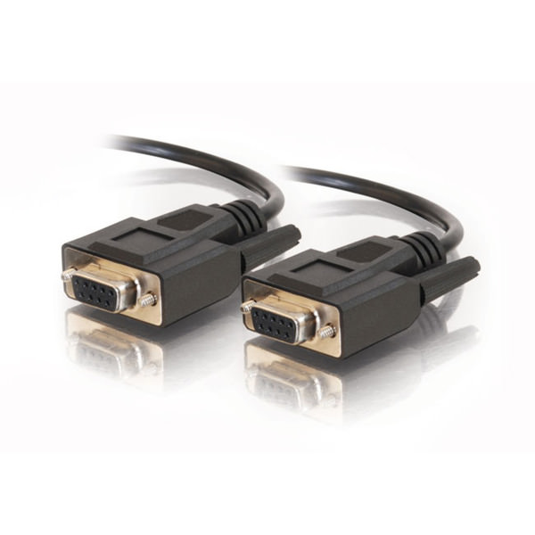
Female DB9 Cable
For boards exposing M_CAN using male DB9 connectors, a female connector is required. The other side can be male or female depending on the other CAN device the user connects to.
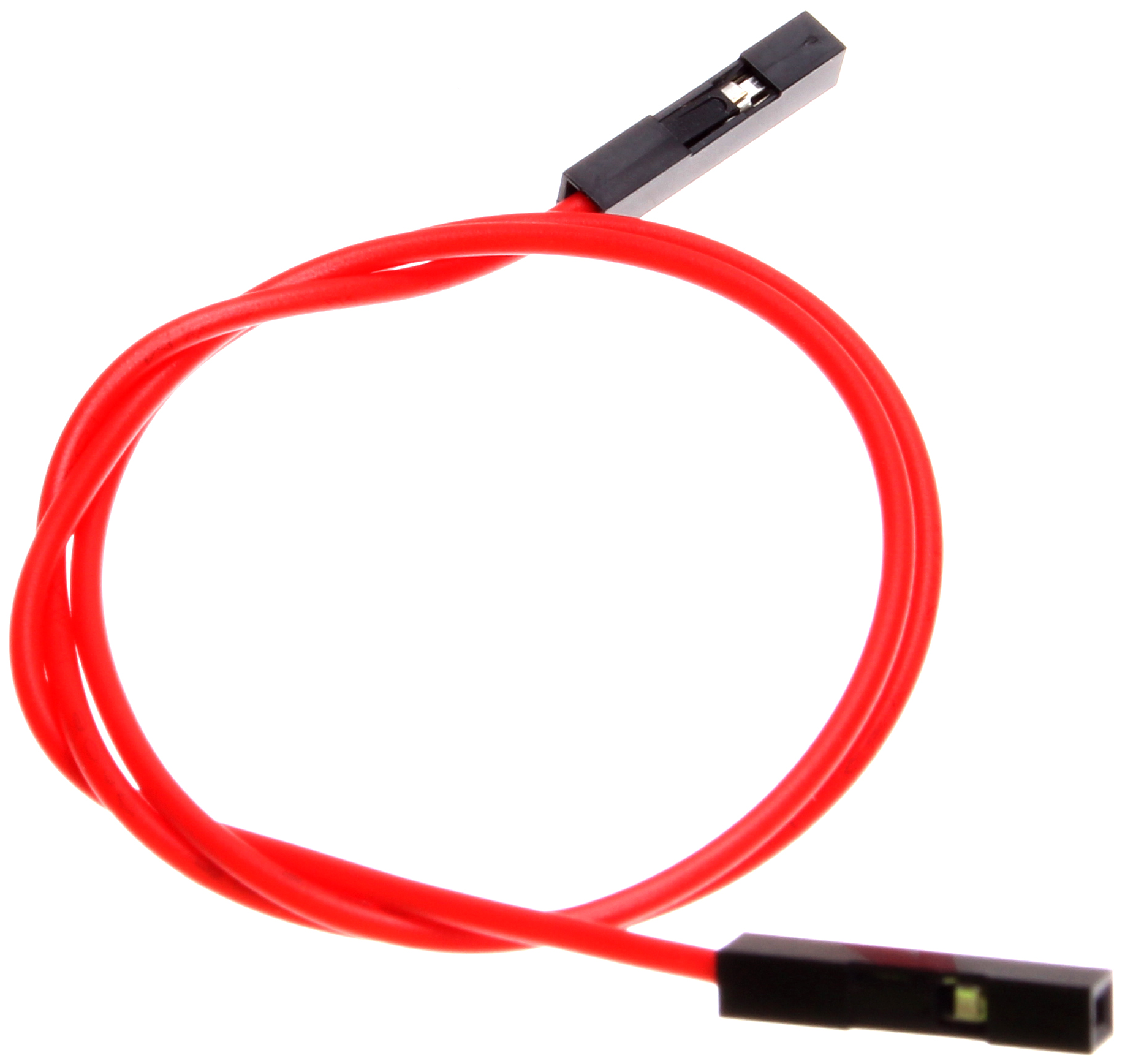
Jumper Wires
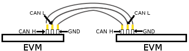
For boards where the CAN pins are broken out via a header, female jumper cables will be ideal for connection. The CAN pins will be CAN H (typically pin 1 of the header), GND (middle pin of the header) and CAN L (lowest pin on the header). The pinout in the header might vary across different boards and users must consult the board’s schematic to verify this.
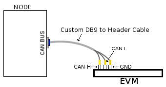
Custom DB9 to Header Cable
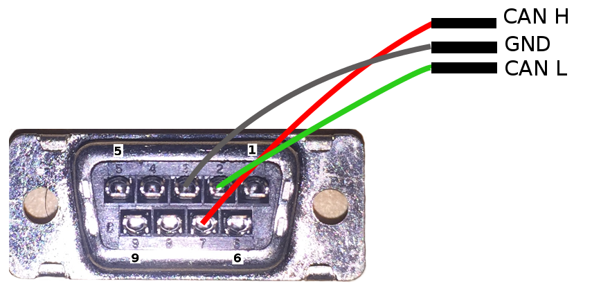
Typically CAN devices use a DB9 connection therefore for boards whose CAN pins are broken out via a header it is helpful to create a header to DB9 connector cable. This custom cable is simple to make. Either a male or female DB9 connector (not cable) must be obtained along with three female jumper wires.
Snip one end of each of the jumper wires and expose some of the wiring. Now solder each of the exposed wires to pin 7 (CAN H), pin 2 (CAN L) and pin 3 (GND). Make sure your soldering on the side of the DB9 that has the metal lip meant to push some of the exposed wire into and soldering to the correct pins correctly. Use the below diagram as a reference.
|
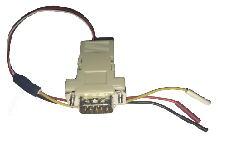
|
| Wiring Diagram | Example of completed cable. |
CAN Utilities
There may be other userspace applications that can be used to interact with the CAN bus but the SDK supports using Canutils which is already included in the sdk filesystem.
Note
These instructions are for can0 (first and perhaps only CAN instance enabled). If the board has multiple CAN instances enabled then they can be referenced by incrementing the CAN instance number. For example 2 CAN instances will have can0 and can1.
Quick Steps
Initialize CAN Bus
- Set bitrate
$ ip link set can0 type can bitrate 1000000
- CAN-FD mode
$ ip link set can0 type can bitrate 1000000 fd on
- CAN-FD mode with bitrate switching
$ ip link set can0 type can bitrate 1000000 dbitrate 4000000 fd on
Start CAN Bus
- Device bring up
Bring up the device using the command:
$ ip link set can0 up
Transfer Packets
Cansend
Used to generate a specific can frame. The syntax for cansend is as follows:
<can_id>#{R|data}          for CAN 2.0 frames
<can_id>##<flags>{data}    for CAN FD frames
Some examples:
- Send CAN 2.0 frame
$ cansend can0 123#DEADBEEF
- Send CAN FD frame
$ cansend can0 113##2AAAAAAAA
- Send CAN FD frame with BRS
$ cansend can0 143##1AAAAAAAAA
Cangen
Used to generate frames at equal intervals. The syntax for cangen is as follows:
cangen [options] <CAN interface>
Some examples:
- Full load test with polling, 10 ms timeout
$ cangen can0 -g 0 -p 10 -x
b. fixed CAN ID and length, inc. data, canfd frames with bitrate switching
$ cangen vcan0 -g 4 -I 42A -L 1 -D i -v -v -f -b
Candump
Candump is used to display received frames.
candump [options] <CAN interface>
Example:
$ candump can0
Note: Use Ctrl-C to terminate candump
Further options for all canutils commands are available at https://git.pengutronix.de/cgit/tools/canutils
Stop CAN Bus
Stop the can bus by:
$ ip link set can0 down
3.3.4.7. DCAN
Introduction
The Controller Area Network is a serial communications protocol which efficiently supports distributed real-time control with a high level of security. The DCAN module supports bitrates up to 1 Mbit/s and is compliant to the CAN 2.0B protocol specification. The core IP within DCAN is provided by Bosch.
This wiki page provides usage information of DCAN Linux driver.
Acronyms & definitions
| Acronym | Definition |
|---|---|
| CAN | Controller Area Network |
| BTL | Bit timing logic |
| DLC | Data Length Code |
| MO | Message Object |
| LEC | Last Error Code |
| FSM | Finite State Machine |
| CRC | Cyclic Redundancy Check |
Table: DCAN Driver: Acronyms
Setup Details
EVM List
| SoC | EVM | Number of Instances | Connection Type | Enabled by default |
|---|---|---|---|---|
| AM335x | General Purpose EVM | 1 | DB9 | No |
| AM437x | General Purpose EVM | 2 | DB9 | Yes |
| 66AK2Gx | General Purpose EVM | 2 | DB9 | Yes |
| AM571x | Industrial Development Kit | 1 | Header | Yes |
| DRA74x | Evaluation Module | 1 | Header | Yes |
| DRA72x | Evaluation Module | 1 | Header | Yes |
Table: EVMs DCAN Driver is Validated on
NOTE On AM335x GP EVM CAN does not work by default. The evm must have its “Profile Switch” set to 1 to enable CAN support.
Hardware/Software Changes to Enable CAN Support
AM335x General Purpose EVM
Most TI boards by default will allow the user to use CAN without any changes. The boards that do require modifications to be enabled for CAN to work will be listed below.
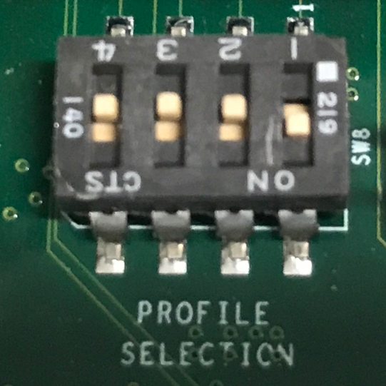
|
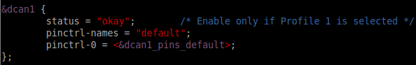
|
| enable) | disabled to okay |
Table: AM335x Hardware and Software modifications
By default the CAN signals on the AM335x GP EVM isn’t routed to the CAN connector. To do so you must configure the EVM to profile 1 instead of profile 0 which is the default. The profile switch can be found in front of the LCD screen next to the brown ribbon cable. Pictures of the EVM using profile 1 is shown above.
Since CAN from a hardware perspective isn’t enabled on the EVM by default it is kept disabled by default. Luckily to re-enable it is relatively simple. The user must edit the am335x-evm.dts (device tree file used for this specific evm). Edit the dcan1 node by changing the node’s status from “disabled” to “okay”. Example of this change can be seen above.
Connection Configuration
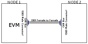
|
|
|
| DB9 to DB9 | Header to Header | Header to DB9 |
Table: Various DCAN EVM Connection Configuration
Equipment
Female DB9 Cable
A male DB9 connector is used on select evms. Therefore, a female DB9/Serial Port/RS 232 cable must be used to connect with the evm. Wheather the other end of the cable is female or male will depend on if the other CAN device the user will be connecting to.
Jumper Wires
For evms whose DCAN pins are broken out via a header then a female jumper wire would be best to use to connect to the various DCAN pins on the evm. Note some evms have CAN H (typically header pin 1), GND (typically middle header) and CAN L (typically the third header). Its important to always connect the CAN’s GND pin to what other device your connecting to. Only exception are the evms that don’t include the CAN GND pin.
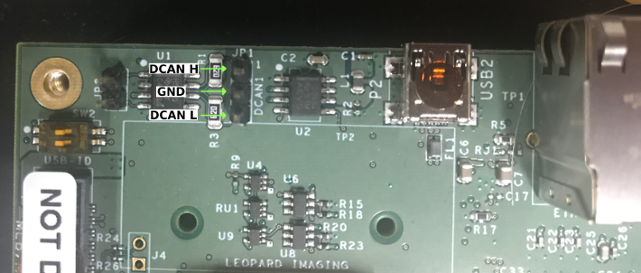
|
| Example of DCAN header on DRA72 EVM |
NOTE Its important for the user to verify which header pin is associated with the various CAN signals. Unless there are already silk screens the user may need to double check the evm’s schematic.
Custom DB9 to Header Cable
Typically CAN devices use a DB9 connection therefore for evms whose CAN pins are broken out via a header it is helpful to create a header to DB9 connector cable. This custom cable is simple to make. Either a male or female DB9 connector (not cable) must be purchased along with three female jumper wires.
Snip one end of each of the jumper wires and expose some of the wiring. Now solder each of the exposed wires to pin 7 (CAN H), pin 2 (CAN L) and pin 3 (GND). Make sure your soldering on the side of the DB9 that has the metal lip meant to push some of the exposed wire into and soldering to the correct pins correctly. Use the below diagram as a reference.
|
|
|
| Wiring Diagram | Example of completed cable. |
CAN Utilities
There may be other userspace applications that can be used to interact with the CAN bus but the SDK supports using Canutils which is already included in the sdk filesystem.
NOTE These instructions are for can0 (first and perhaps only CAN instance enabled). If the board has multiple CAN instances enabled then they can be referenced by incrementing the CAN instance number. For example 2 CAN instances will have can0 and can1.
Quick Steps
Initialize CAN Bus
- Set bit-timing
Set the bit-rate to 50Kbits/sec using the following command:
$ ip link set can0 type can bitrate 50000
- Set bit-timing (loopback mode)
Set the bit-rate to 50Kbits/sec with triple sampling in the loopback mode using the following command
$ ip link set can0 type can bitrate 50000 loopback on
Start CAN Bus
- Device bring up
Bring up the device using the command:
$ ip link set can0 up
NOTE The default state when starting a previously powered off CAN device is called “Error-Active”. So don’t worry when you see this command when you first start the CAN instance.
Send or Receive Packets
- Transfer packets
Packet transmission can be achieve by using cansend and cansequence utilities.
Transmit 4 bytes with standard packet id number as 0x123
$ cansend can0 123#DEADBEEF
Transmit a sequence of can frames with random IDs and random data.
$ cangen can0
- Receive packets
Packet reception can be achieve by using candump utility
$ candump can0
Stop CAN Bus
$ ip link set can0 down
Advanced Usage
The following are some examples exploring the capabilties of can-utils. See can-utils documentation for a comprehensive set of options.
Transmit fixed CAN ID and length with an incrementing data
$ cangen can0 -g 4 -I 42A -L 1 -D i -v -v
Log only error frames but no data frames
$ candump -l any,0~0,#FFFFFFFF
Statistics of CAN
Statistics of CAN device can be seen from these commands
$ ip -d -s link show can0
Below command also used to know the details
$ cat /proc/net/can/stats
Error frame details
DCAN IP Error details
If the CAN bus is not properly connected or some hardware issues DCAN has the intelligence to generate an Error interrupt and corresponding error details on hardware registers.
In CAN terminology errors are divided into three categories
- Error warning state, this state is reached if the error count of transmit or receive is more than 96.
- Error passive state, this state is reached if the core still detecting more errors and error counter reaches 127 then bus will enter into
- Bus off state, still seeing the problems then it will go to Bus off mode.
DCAN driver provides
For the above error state, driver will send the error frames to inform that there is error encountered. Frame details with respect to different states are listed here:
- Error warning frame
<0x004> [8] 00 08 00 00 00 00 60 00
ID for error warning is 0x004 [8] represents 8 bytes have received 0x08 at 2nd byte represents type of error warning. 0x08 for transmission error warning, 0x04 for receive error warning frame 0x60 at 7th byte represent tx error count.
- Error passive frame
<0x004> [8] 00 10 00 00 00 00 00 64
ID for error passive frame is 0x004 [8] represents 8 bytes have received 0x10 at 2nd byte represents type of error passive. 0x10 for receive error passive, 0x20 for transmission error passive 0x64 at 8th byte represent rx error count.
- Buss off state
<0x040> [8] 00 00 00 00 00 00 00 00
ID for bus-off state is 0x040
Error frames display with candump
candump has the capability to display the error frames along with data frames on the console. Some of the error frames details are mentioned in the previous section
$ candump can0 -e
Linux Driver Configuration
- DCAN device driver in Linux is provided as a networking driver that confirms to the socketCAN interface
- The driver is currently build-into the kernel with the right configuration items enabled (details below)
Detailed Kernel Configuration
The SoC specific kernel configuration included in the SDK by default enables full support for the DCAN driver. Therefore, manually enabling these options are not required if your using the provided kernel config (defconfig).
The below CAN specific drivers are the bare minimum needed to enable DCAN driver:
- CAN bus subsystem support
- Bosch C_CAN/D_CAN devices
- CAN_C_CAN_PLATFORM
Four additional drivers are required to utilize all the CAN features:
- Raw CAN Protocol (raw access with CAN-ID filtering)
- Broadcast Manager CAN Protocol (with content filtering)
- CAN Gateway/Router (with netlink configuration)
- CAN bit-timing calculation
[*] Networking support ->
   <*|M> CAN bus subsystem support ->
      <*|M> Raw CAN Protocol (raw access with CAN-ID filtering)
      <*|M> Broadcast Manager CAN Protocol (with content filtering)
      <*|M> CAN Gateway/Router (with netlink configuration)
         CAN Device Drivers ->
            <*|M>   Platform CAN drivers with Netlink support
            [*]     CAN bit-timing calculation
            <*|M>   Bosch C_CAN/D_CAN devices ->
               <M> Generic Platform Bus based C_CAN/D_CAN driver
NOTE *|M means can be either be built into the kernel or enabled as a kernel module.
DCAN driver Architecture
DCAN driver architecture shown in the figure below, is mainly divided into three layers Viz user space, kernel space and hardware.
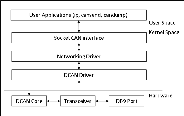
User Space
CAN utils are used as the application binaries for transfer/receive frames. These utils are very useful for debugging the driver.
Kernel Space
This layer mainly consists of the socketcan interface, network layer and DCAN driver.
Socketcan interface provides a socket interface to user space applications and which builds upon the Linux network layer. DCAN device driver for CAN controller hardware registers itself with the Linux network layer as a network device. So that CAN frames from the controller can be passed up to the network layer and on to the CAN protocol family module and vice-versa.
The protocol family module provides an API for transport protocol modules to register, so that any number of transport protocols can be loaded or unloaded dynamically.
In fact, the can core module alone does not provide any protocol and cannot be used without loading at least one additional protocol module. Multiple sockets can be opened at the same time, on different or the same protocol module and they can listen/send frames on different or the same CAN IDs.
Several sockets listening on the same interface for frames with the same CAN ID are all passed the same received matching CAN frames. An application wishing to communicate using a specific transport protocol, e.g. ISO-TP, just selects that protocol when opening the socket. Then can read and write application data byte streams, without having to deal with CAN-IDs, frames, etc.
Hardware
This layer mainly consisting of DCAN core and DCAN IO pins for packet Transmission or reception.
Driver Location
| S.No | Location | Description |
|---|---|---|
| 1 | drivers/net/can/c_can/c_can.c | DCAN driver core file |
| 2 | drivers/net/can/c_can/c_can_platform.c | Platform/SoC DCAN bus driver |
3.3.4.8. DSS
Introduction
This page gives a basic description of DSS hardware, the Linux kernel drivers (omapdss and omapdrm) and various TI boards that use DSS. The technical reference manual (TRM) for the SoC in question, and the board documentation give more detailed descriptions.
This page applies to TI’s v4.9 kernel, but most of it is also valid for mainline and for older kernels. Some features may be missing from mainline.
Supported Devices
There are many DSS IP versions, all of which support slightly different set of features. All the DSS IP versions are supported by the same driver.
This page applies to the following TI SoCs or SoC families: OMAP2, OMAP3, OMAP4, OMAP5, AM5, AM4, DRA7, K2G.
Hardware Architecture
The Display Subsystem (DSS) is a hardware block responsible for fetching pixel data from memory and sending it to a display peripheral like an LCD panel or a HDMI monitor. DSS hardware can be divided into two major parts: 1) DISPC, which handles fetching the pixel data, doing color conversions, composition, and other pixel manipulation, and 2) encoders, which encode the raw pixel data to standard display signals, like HDMI or MIPI DPI. In addition to the SoC’s DSS, boards often contain external encoders (for example, DPI to DVI encoder) and display panels.
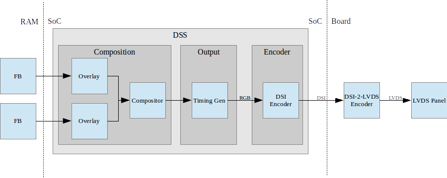
Simplified example setup where two overlays are merged into one output, which is encoded into DSI, then to LVDS, and shown on an LVDS panel.
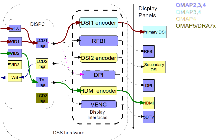
An overview of the DSS hardware. The arrows show how ovlerlays/pipelines are connected to overlay managers, which are further connected to encoders, which finally create an encoded pixel stream for display on to LCD or TV. The different colors of the blocks show the new sub-blocks added in subsequent DSS revisions
Display Controller (DISPC)
DISPC is the block which is responsible of fetching pixel data from the memory through DMA pipelines, and then create a pixel stream for the encoder. The pixel stream comprises of a composition of one or more image layers which we finally want to present on the display. DISPC can be split into 2 major sub-blocks:
Overlays
Overlays (or Pipelines or DMA channels) consist of the HW block which perform DMA to fetch image pixels (of different color formats) from RAM. Besides performing DMA, overlays perform other functions like replication, ARGB expansion, scaling, color conversion, VC1 range mapping on the input pixels before it’s passed on to the overlay manager. An overlay manager receives pixel data from one or more such pipelines, and performs the task of composing them and passing it on to the encoder.
Most DSS IP versions has two types of overlays: a GFX overlay and a number of VIDEO overlays. GFX overlay doesn’t support scaling or YUV color formats and are generally intended to display a user interface. VIDEO overlays support up/down scaling and YUV color formats. The number of overlays within DSS varies with the DSS IP version used in the SoC.
Overlay Managers (Compositors and timing generators)
Overlay managers are the blocks which take pixel data from one or more overlays, layer them to form a composition, and create a pixel stream with the timings as per required by the encoder/panel.
The compositor part takes pixel data from multiple overlays, composing them on the basis of their position with respect to the complete overlay manager size. Tasks like alpha blending, color-keying, z-order and color phase rotation, dithering are also performed by the compositor in the overlay manager.
The timing generator part of the overlay manager is responsible of providing the pixel stream generated by the compositor above according to the timings desired by the encoder or the panel. The timing generator is a state machine which provides RGB data along with control signals like pixel clock, hsync, vsync, data enable. This timing info is used by the encoder/panel to display the composited frame on the screen.
Most DSS IP versions have two types of overlay managers. LCD managers are primarily used for encoders like DPI, DSI and RFBI which connect to LCD panels. The timing generator derives its pixel clock from either the DSS functional clock, or a PLL within the DSS. TV managers are primarily used for encoders like HDMI and VENC which connect to TV and monitors. The timing generator derives gets the pixel clock from the connected encoder.
The number of overlay managers within DSS varies with the DSS IP version used in the SoC.
Display Encoders (or interfaces)
Encoders take a pixel stream from an overlay manager, and encode it into a standard video signal which is understood by the LCD panel/monitor. These video standards are specified by MIPI or general video/display bodies.
- MIPI DPI encoder: This is the simplest encoder, it passes the overlay manager video port output (consisting of RGB data lines and control signals) directly to SoC pins. The number of RGB data lines used is configurable, and is set on the basis of the color depth supported by the LCD panel.
- HDMI encoder: This adapts the HDMI spec. It consists of a CORE block which implements the HDMI protocol, a PLL block which provides the clock required for the pixel clock and HDMI TMDS lines, and a PHY block which encodes the pixels and data into the TMDS format.
- MIPI DSI encoder: This encoder takes parallel RGB data from an overlay manager video port, and encodes it into a serial format. It consists of the Protocol engine which implements the MIPI DSI spec to create serial data, and command information, a PLL block which provides clocks to the overlay manager, protocol engine and the PHY, a DSI PHY block which follows the MIPI D-PHY spec, this uses a LVDS like protocol to transmit serial data to the DSI display. DSI supports 2 modes, command and video modes. More info can be found in the TRM.
- MIPI DBI/RFBI encoder: This encoder transmits data to a panel without any timing generation info. The panel is expected to have an internal buffer which it displays on to the LCD using it’s own timing generator.
- VENC encoder: This encoder converts digital pixel data into a composite or s-video analog output supporting the NTSC and PAL standards. It’s hardly used these days.
The number and types of encoders within DSS varies with the DSS IP version used in the SoC.
SoC Hardware Features
AM4
- 1 GFX overlay
- XRGB4444, ARGB4444, RGB565
- RGB888
- XRGB8888, ARGB8888, RGBA8888
- 2 VIDEO overlays
- XRGB4444, ARGB4444 (VID2), RGB565
- RGB888
- XRGB8888, ARGB8888 (VID2), RGBA8888 (VID2)
- UYVY, YUYV
- 1 MIPI DPI output
OMAP5
- 1 GFX overlay
- XRGB4444, RGBX4444, ARGB4444, RGBA4444, RGB565, XRGB1555, ARGB1555
- RGB888
- XRGB8888, RGBX8888, ARGB8888, RGBA8888, BGRA8888
- 3 VIDEO overlays
- XRGB4444, RGBX4444, ARGB4444, RGBA4444, RGB565, XRGB1555, ARGB1555
- RGB888
- XRGB8888, RGBX8888, ARGB8888, RGBA8888, BGRA8888
- UYVY, YUYV, NV12
- 1 MIPI DPI outputs
- 2 MIPI DSI outputs
- 1 HDMI output
DRA7 / AM5
- 1 GFX overlay
- XRGB4444, RGBX4444, ARGB4444, RGBA4444, RGB565, XRGB1555, ARGB1555
- RGB888
- XRGB8888, RGBX8888, ARGB8888, RGBA8888, BGRA8888
- 3 VIDEO overlays
- XRGB4444, RGBX4444, ARGB4444, RGBA4444, RGB565, XRGB1555, ARGB1555
- RGB888
- XRGB8888, RGBX8888, ARGB8888, RGBA8888, BGRA8888
- UYVY, YUYV, NV12
- 3 MIPI DPI outputs
- 1 HDMI output
Driver Architecture
The driver for DSS IP is omapdrm. omapdrm is a Direct Rendering Manager (DRM) driver, located in the directory drivers/gpu/drm/omapdrm/ in the kernel tree. omapdrm does not implement any 3D GPU features, only the Kernel Mode Setting (KMS) features, used to display pixel data on a display.
In addition to omapdrm, there are a number of encoder and panel drivers implementing support for encoders and panels located in drivers/gpu/drm/omapdrm/displays/ .
omapdrm
omapdrm is internally divided into smaller drivers for each DSS IP submodule. These include DPI, DSI, HDMI drivers.
The mapping of DRM entities to DSS hardware is roughly as follows:
plane     -> DSS pipeline/overlay
crtc      -> DSS overlay manager
encoder   -> DSS output, encoder, display
connector -> DSS output, encoder, display
Driver Features
Note: this is not a comprehensive list of features supported/not supported.
Supported Features
LCD Outputs:
- MIPI DPI
- Active matrix
- RGB
HDMI output:
- Progressive
- Interlace (with progressive content)
- 24-bit RGB
DRM Plane Features:
- Scaler
- Z-order
- Global alpha blending
- Alpha blending (pre-multipled & non-pre-multiplied)
DRM CRTC Features:
- Background color
- Transparency color keying
- Color Phase Rotation
Unsupported Features/Limitations
- Rotation/Tiler 2D (Partially supported by the driver, but almost unusable due to HW limitations)
- Interlaced content is not supported.
- Information about interlace top/bottom fields is not given to the userspace, and the userspace has no control if a buffer is shown on top/bottom.
- On DRA7 and AM5 the driver has limitations on the possible combinations of VOUTs that are usable at the same time. The maximum number of supported VOUTs is the same as the number of video PLLs, i.e. 1 on DRA72x/AM571x and 2 on DRA74x/AM572x. When using two VOUTs, VOUT1 and VOUT3 should be used (other combinations can be used with minor driver modification).
LCD output:
- CLUT (Color Look-Up Table) color formats are not supported (BITMAP1, BITMAP2, BITMAP4, BITMAP8)
- Passive matrix
- TDM
- BT-656/1120
- MIPI DBI/RFBI
- Interlace
HDMI output:
- HDCP
- Deep color modes
- YUV output
Driver Configuration
Kernel Configuration Options
omapdrm supports building both as built-in or as a module.
omapdrm can be found under “Device Drivers/Graphics support” in the kernel menuconfig. You need to enable DRM (CONFIG_DRM) before you can enable omapdrm (CONFIG_DRM_OMAP).
- Enable OMAP2+ Display Subsystem support (CONFIG_OMAP2_DSS) for
AM4/OMAP5/DRA7/AM5 SoCs
- From the submenu, select the DSS outputs you need
- Enable TI DSS6 support (CONFIG_TI_DSS6) for K2G SoC
- Enable the encoders and panels under OMAPDRM External Display Device Drivers
Driver Usage
Loading omapdrm
If built as a module, you need to load all the drm, omapdrm, encoder and panel modules before omapdrm will start. When omapdrm starts, it will prints something along these lines:
[   12.858392] [drm] Supports vblank timestamp caching Rev 2 (21.10.2013).
[   12.865153] [drm] No driver support for vblank timestamp query.
[   12.884131] [drm] Enabling DMM ywrap scrolling
[   12.891551] omapdrm omapdrm.0: fb0: omapdrm frame buffer device
[   12.926796] [drm] Initialized omapdrm 1.0.0 20110917 on minor 0
Using omapdrm
omapdrm is usually used by the windowing system like X server or Weston, so normally users don’t need to use omapdrm directly.
omapdrm device appears under /dev/dri/ directory, normally card0.
There are also newer DRM device nodes, controlD64 and renderD128 which point to the same omapdrm device. controlD64 is a “control” node, used for mode setting. renderD128 is a “render” node, which in omapdrm’s case means that only buffer allocations can be done via the render node. The render node can be given more relaxed access restrictions, as the applications can only do buffer allocations from there, and cannot affect the system (except by allocating all the memory).
Low level userspace applications can use omapdrm via DRM ioctls. This is made a bit easier with libdrm, which is a wrapper library around DRM ioctls.
libdrm is included in TI releases and its sources can be found from:
git://anongit.freedesktop.org/git/mesa/drm
libdrm also contains ‘modetest’ tool, which can be used to get basic information about DRM state, and to show a test pattern on a display.
Another option is kms++, a C++11 library for kernel mode setting which includes a bunch of test utilities and also V4L2 classes and Python wrappers for DRM and V4L2. kms++ can be found from:
https://github.com/tomba/kmsxx
There are also other examples and tests that can be used to learn about DRM:
Dual camera demo:
http://git.ti.com/sitara-linux/dual-camera-demo/trees/master
omapdrm properties
omapdrm supports configuration via DRM properties. Many of them are standard, but some are omapdrm specific.
| Property | Object | Description |
|---|---|---|
| zorder | plane | Z order of a plane. The higher the number the more top the plane is, hiding other planes beneath it. This is supported on OMAP4+ DSS IPs. Earlier DSS IPs have a fixed z-order. |
| global_alpha | plane | Global alpha value for a plane. |
| pre_mult_alpha | plane | If set, the pixel data is considered pre-multiplied with alpha. |
| COLOR_ENCODING | plane | OMAP4+: Selects between BT.601 and BT.709 YCbCr encoding. |
| COLOR_RANGE | plane | OMAP4+: Selects between full range and limited range YCbCr encoding. |
| trans-key-mode | crtc | Transparency key mode: disable, gfx-dts, vid-src. |
| trans-key | crtc | Transparency key color. |
| background | crtc | Background (“default”) color. |
| alpha_blender | crtc | OMAP3/AM4: Enable alpha blender, which also changes the fixed z-order. |
| CTM | crtc | OMAP4+: Color Transformation Matrix blob property. Implemented trough Color phase rotation matrix in DSS IP. Applied after gamma table. Not available on OMAP4+ TV output. |
| GAMMA_LUT | crtc | OMAP4+ & DSS6: Blob property to set the gamma lookup table (LUT) mapping pixel data sent to the connector. |
| GAMMA_LUT_SIZE | crtc | OMAP4+ & DSS6: Number of elements in gammma lookup table. |
Buffers
The buffers used for omapdrm can be either allocated from omapdrm or imported from some other driver (dmabuf import).
omapdrm supports generic DRM dumb buffers and omapdrm specific buffers (omap_bo). Dumb buffers are allocated using the generic DRM_IOCTL_MODE_CREATE_DUMB ioctl. omap_bos are allocated using the omapdrm specific DRM_IOCTL_OMAP_GEM_NEW ioctl, but libdrm offers wrappers for omap_bo allocation.
On SoCs with TILER (OMAP4/5, AM5, DRA7) the driver supports scatter-gather lists for both allocated and imported buffers. On SoCs without TILER the allocated memory is always from the contiguous DMA memory pool, and imported memory must be contiguous memory.
Debugging
There are two debugfs directiories that can be used when debugging omapdrm:
/sys/kernel/debug/omapdrm/ contains debugfs files for the DSS hardware. It can be used to get register dumps of the IP blocks, and to get information about the clock setup.
/sys/kernel/debug/dri/ contains debugfs files for the DRM. It can be used to see the framebuffers allocated, the connectors, information about tiler.
fbdev emulation (/dev/fb0)
DRM framework supports “emulating” the legacy fbdev API. This feature can be enabled or disabled in the kernel config (CONFIG_DRM_FBDEV_EMULATION). The fbdev emulation offers only basic feature set and the fb is shown on the first display. Fbdev emulation is mainly intended for kernel console or boot splash screens.
Module parameters
displays
‘displays’ module parameter can be used to reorder or remove the displays that omapdrm uses. If the board has two displays, LCD and HDMI, and the device tree data defines LCD as display0 and HDMI as display1, then:
omapdrm.displays=0,1 - represents the original order (LCD, HDMI)
omapdrm.displays=1,0 - represents reverse order (HDMI, LCD)
omapdrm.displays=0 - only the LCD is enabled
omapdrm.displays=1 - only the HDMI is enabled
omapdrm.displays=-1 - disable all displays
TI Board Specific Information
The below section provides details on TI board specific DSS features and limitation.
AM4 Boards
Features & Limitations
On the EVM board, we use DPI LCD panel of resolution 800 x 480. The LCD panel is 7 inch touch panel (OSD057T0559-34TS) from OSD displays. Silicon Image’s SiI9022 is the DPI to HDMI converter available on board to provide HDMI output. Due to memory bandwidth limitations the board only supports a maximum of 720p@60.
As AM4 only has a single output, both LCD and HDMI cannot be enabled at the same time. Selecting the display to be used if done by using the appropriate .dtb file.
DRA7 EVM
On the DRA7 EVM, DSS outputs are connected as follows:
DPI1/VOUT1 -> LCD panel (LCD type can be 7" or 10" LG or 10" OSD panel connected via a daughter card).
DPI2/VOUT2 -> Unused.
DPI3/VOUT3 -> FPD Link (Optional. Panel to be connected to a serializer/de-serializer board via FPDLink cable).
HDMI -> HDMI connector.
The used LCD panel is chosen by selecting the appropriate .dtb file.
3.3.4.9. LCDC
AM335x LCDC DRM Display Driver
Introduction
This page gives a brief description of LCDC usage with tilcdc DRM driver. The obsolete fbdev driver wiki page also remains at the end of this page.
This document applies TI’s v4.4 kernel and mainline v4.9 kernel with tilcdc DRM atomic modeset support.
Generic DRM Information
What is DRM: https://dri.freedesktop.org/wiki/DRM/
What do the abbreviations KMS/GEM/DRM actually stand for: Kernel Mode Setting, Graphics Execution Manager, Direct Rendering Manager.
Where can I find DRM documentation?
- Online at: https://www.kernel.org/doc/htmldocs/drm/index.html
- Or in kernel directory:
- make htmldocs
Use web browser to view: Documentation/DocBook/drm.html
- DRM (dri/kms/gem) documentation is available here
Hardware and How It Is Used
The LCD controller can be used in two independent modes. Either in the raster controller mode or in LCD interface display driver (LIDD) mode. The tilcdc driver support only raster controller mode.
Compared to most other DRM supported devices the LCDC provides very limited functionality. It supports only one simple framebuffer or alternatively two framebuffers that are automatically flipped back and forth. The tilcdc driver uses single buffer mode and flips framebuffer by changing the framebuffer’s DMA address. This does not interfere with the DMA of the currently drawn frame.
The LCDC supports 1-, 2-, 4-, 8-, 12-, 16-, and 24-bits per pixel modes. The 1-, 2-, 4-, and 8-bpp modes are palette modes and are not supported by the tilcdc driver. With the 12-, 16-, and 24-bit modes the choice is limited to 16 and 24 bpp modes, and the 24 bpp mode is only supported by revision 2 LCDC. There is also a problem is using 16- and 24-bit modes with same HW, see tilcdc Supported Features below.
LCDC memory bandwidth issues
LCDC sometimes suffers from memory bandwidth issues when high pixel clocks and high bits per pixel colour formats are used. These bandwidth issues manifest themselves as DMA FIFO underflow and frame synchronization lost errors. The problem is solved on Beaglebone-Black and am335x-evm with this patch. The patch is available in u-boot release version ti2017.01 (Processor SDK version 4.0) onwards. A similar u-boot change is needed for any other HW suffering from the same problem. Please check the ddr_data for am3-evm or beaglebone-black in the u-boot config. If after using the patch you still see issues, you may need to further tune the value of REG_PR_OLD_COUNT per your system need.
tilcdc Supported Features
- RGB565 color format
- or RGB888/XRGB8888 color formats (LCDC rev2 only)
- The 16-bit and 24-bit video has Red and Blue wires swapped and depending on the wiring of the board ether 16-bit or 24-video is in BGR format (see section 3.1.1 in AM335x Silicon Errata)
- Panel timings controlled from dts file
- TDA998x HDMI encoder support on BeagleBone Black
- Pixel clock to 126MHz allowing resolutions up to 1920x1080p24
- Fbdev emulation is provided through /dev/fb0
- HDMI audio support with corresponding ALSA sink (not in mainline for the time being)
- HDMI EDID support
- DRM Atomic modeset support since Linux 4.9 and in ti2016.04
tilcdc Unsupported Features:
- No HDMI hotplug
- 1920x1080@60 is not supported due to pixel clock requirements being too high for the AM335x hardware.
Configuring into kernel build:
- By default DRM support for LCDC is not built in to the kernel when using omap2plus_defconfig.
- Make sure that the following are disabled from .config as the
fbdev driver cannot coexist with the DRM driver.
- CONFIG_FB_DA8XX
- CONFIG_FB_DA8XX_TDA998X
- And add:
- CONFIG_DRM=y/m
- CONFIG_DRM_I2C_NXP_TDA998X=y/m
- CONFIG_DRM_TILCDC=y/m
If using modules, it is enough to load tilcdc module, and tda998x module if using beaglebone-black. It does not matter in which order the modules are loaded.
Required Device Tree Nodes:
- See .txt files in - Documentation/devicetree/bindings/drm/tilcdc
- For Beaglebone-Black see also: Documentation/devicetree/bindings/display/bridge/tda998x.txt
- The am335x-boneblack.dts, am335x-evm.dts, and am335x-evmsk.dts have the necessary nodes for LCDC DRM driver
Example Device Tree nodes to enable HDMI with DRM on BeagleBone Black:
&lcdc {
    status = "okay";

    port {
        lcdc_0: endpoint@0 {
            remote-endpoint = <&hdmi_0>;
        };
    };
};
&i2c0 {
    tda19988: tda19988 {
        compatible = "nxp,tda998x";
        reg = <0x70>;

        #sound-dai-cells = <0>;
        audio-ports = <  TDA998x_I2S 0x03>;

        ports {
            port@0 {
                hdmi_0: endpoint@0 {
                    remote-endpoint = <&lcdc_0>;
                };
            };
        };
    };
};
Examples for using DRM:
The drm userspace components and test applications are available from: https://cgit.freedesktop.org/mesa/drm/
A useful tool contained in this suite is modetest.
- On BeagleBone Black you can use modetest to try the different resolutions that are supported by the attached monitor.
- For example:
- modetest –s 5:1280x720@XB24
- Will change the HDMI output to 1280x720 – the XB24 tells modetest to use the correct pixel format of XBGR8888.
Legacy AM335x LCDC fbdev Display Driver
This driver is currently obsolete (has been since ti-linux-3.14.y), and is not actively maintained any more. Please use LCDC DRM driver instead.
Introduction:
- Where can I find fbdev documentation:
See Documentation/fb/framebuffer.txt Or online at: https://www.kernel.org/doc/Documentation/fb/framebuffer.txt
LCDC fbdev Supported Features:
- RGB32 pixel format (XBGR32 format)
- Panel timings controlled from dts file
- TDA998x HDMI encoder support on BeagleBone Black
- Pixel clock to 126MHz allowing resolutions up to 1920x1080p24
- Access to driver and framebuffer is through /dev/fb0
LCDC fbdev Unsupported Features:
- No HDMI audio support in fbdev driver
- No HDMI EDID support
- No HDMI hotplug
Configuring into kernel build:
- The necessary .config options are:
- CONFIG_FB_DA8XX
- CONFIG_FB_DA8XX_TDA998X
Required Device Tree Nodes (no HDMI)
- See Documentation/devicetree/bindings/video/da8xx_fb.txt
Required Device Tree Nodes (with HDMI)
- See arch/arm/boot/dts/am335x-boneblack.dts for complete example of how to use.
&i2c0 {
   hdmi1: hdmi@70 {
        compatible = "nxp,tda998x";
        reg = <0x70>;
  };
};

&lcdc {
   hdmi = <&hdmi1>;
   display-timings {
        /* provide your display timings here for HDMI */
   };
};
3.3.4.10. PWM
Introduction
PWMSS software architecture
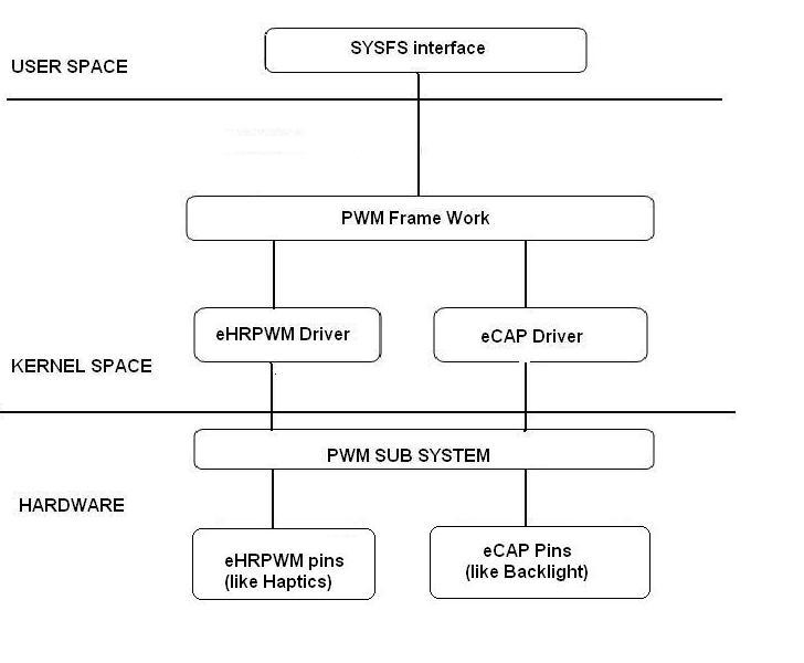
Driver Configuration
Procedure to build eHRPWM driver
Device Drivers --->
        <*> Pulse Width Modulation(PWM) Support --->
           <*> eHRPWM PWM support
Procedure to build eCAP driver
Device Drivers --->
        <*> Pulse Width Modulation(PWM) Support --->
           <*> eCAP PWM support
Driver Usage
eCAP
The current release of the driver supports only PWM mode. eCAP can be controlled from the user space through SYSFS interface. SYSFS interface for eCAP is available at
target$ cat /sys/class/pwm/pwmchipN
Where,
‘N’ is the eCAP instance.
- Request and Control attributes
- Configuration attributes
Note
- Below examples uses eCAP instance 0 (i = 0).
Type 1 attributes
- *export* Attribute.
Ask the kernel to export a PWM channel. Writing 0 to the export attribute Acquires the channel and writing 0 to the unexport attribute Frees/Releases the channel. Before performing any operations, device has to be requested first.
- Request the Device:
target$ echo 0 > /sys/class/pwm/pwmchip0/export
- free the device:
target$ echo 0 > /sys/class/pwm/pwmchip0/unexport
- *run* Attribute
Enable/disable the PWM channel
- Enable the PWM
target$ echo 1 > /sys/class/pwm/pwmchip0/pwm0/enable
- Disable the PWM
target$ echo 0 > /sys/class/pwm/pwmchip0/pwm0/enable
Type 2 attributes
- *period* Attribute
Enter the period in nano seconds value.
target$ echo 1000000000 > /sys /class/pwm/pwmchip0/pwm0/period
- *duty_cycle* Attribute
Enter the Duty cycle value in nanoseconds.
target$ echo val > /sys/class/pwm/pwmchip0/pwm0/duty_cycle
- *Polarity* Attribute.
Setup Signal Polarity
target$ echo 1 > /sys /class/pwm/pwmchip0/pwm0/polarity
target$ echo 0 > /sys /class/pwm/pwmchip0/pwm0/polarity
Controlling backlight
target$ echo val > /sys/class/pwm/pwmchip0/pwm0/duty_cycle
target$ echo val > /sys/class/backlight/backlight.8/brightness
‘val’ can range from 0 to 8.
3.3.4.11. GPIO
GPIO Driver Overview
The GPIO Driver enables the GPIO controllers available on the device. The driver configures the GPIO hardware and interfaces and makes them available to the sysfs interface for user space interaction or other device drivers that need to access pins. For example, a MMC/SD driver may need to read a GPIO as in input to determine if a card is present. The H/W GPIO controllers available will vary by SoC and system configuration.
Overview
The GPIO controllers allow interaction with GPIO pins for input/output and interrupt generation.
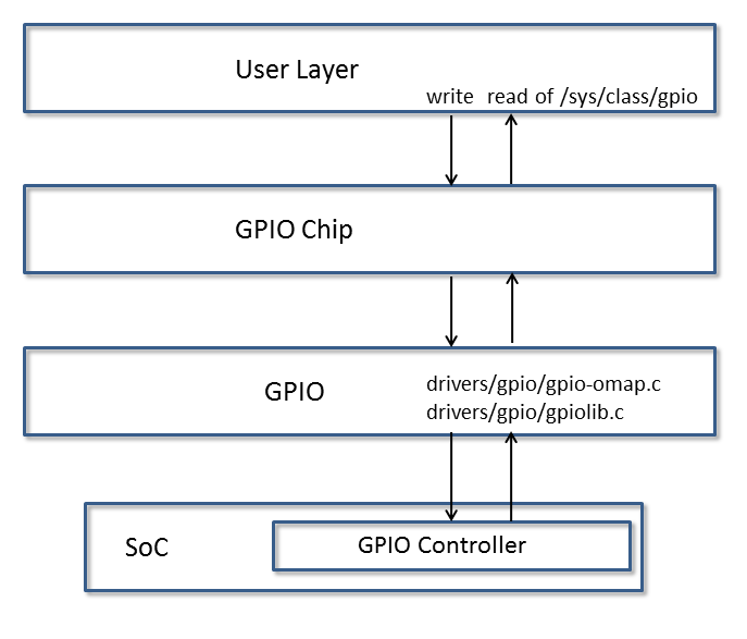
User Layer
The GPIO driver can be used via the sysfs interface in user space or by other drivers that may need to access pins as either input/outputs or interrupts. More information about this driver and GPIO usage in Linux can be found in the kernel documentation:
sysfs
The sysfs interface is for GPIO is located in the kernel at /sys/class/gpio. More information about this interface can also be found in the kernel sources:
For controlling LEDs and Buttons, the kernel has standard drivers, “leds-gpio” and “gpio_keys”, respectively, that should be used instead of GPIO directly.
Consuming Drivers
The GPIO Driver can also be easily leveraged by other drivers to “consume” a GPIO.
For an example of a driver using a GPIO pin, examine this entry in a dts file for how the MMC/SD interface could use a GPIO as a card detect pin here.
Features
- Access GPIO from user space as input or output
- Leverage GPIO from another “consumer” driver
Power Management
gpio_keys: volume_keys@0 node in the
device tree LINUX/arch/arm/boot/dts/am335x-evm.dts as a reference.
GPIO0_31 is configured as a wake source below:`` @am33xx_pinmux { ``
pinctrl-names = "default";
pinctrl-0 = <&test_keys>;
...
test_keys: test_keys {
  0x74 (PIN_INPUT_PULLDOWN | MUX_MODE7);  /* gpmc_wpn.gpio0_31 */
};
...
keys: test_keys@0 {
  compatible = "gpio-keys";
  #address-cells = <1>;
  #size-cells = <0>;
  autorepeat;
  test@0 {
    label = "J4-pin21";
    linux,code = <155>;
    gpios = <&gpio0 31 GPIO_ACTIVE_LOW>;
    gpio-key,wakeup;
  };
};
...
};
3.3.4.12. I2C
Introduction
The device contains high-speed (HS) inter-integrated circuit (I2C) controllers (I2Ci modules, where i = 1, 2, 3 ...), each of which provides an interface between a local host (LH), such as a digital signal processor (DSP), and any I2C-bus-compatible device that connects through the I2C serial bus. External components attached to the I2C bus can serially transmit and receive up to 8 bits of data to and from the LH device through the 2-wire I2C interface.
Each HS I2C controller can be configured to act like a slave or master I2C-compatible device. I2C controllers can work at different frequencies such as 100 KHz, 400 KHz and 3.4 MHz.
For more info, refer to the I2C controller chapter in the respective SOC TRM.
Setting up
Omap I2C is enabled by default in omap2plus_defconfig.
Testing
Test1:
  Check for the following in the boot log
  omap_i2c reg.i2c: bus0 rev0.12 at X KHz
Test2:
  Use the following utilities to check the i2c functionality.
  i2cdump -f -y bus slaveaddr b
     This will dump the register content of the slave at respective bus.
  i2cset -f -y bus slaveaddr register value b
     This will write a 'value' to the 'register' of the device with address 'slaveaddr'.
  i2cget -f -y bus slaveaddr register b
     This will read from the 'register' of the device with address 'slaveaddr'.
  Above testing helps if the slave address clocks are enabled and you can use the
  above tools to quickly get/set the value to just sanity check the i2c functionality.
Test3:
    Check for the devices connected to the I2C.
    Run tests applicable for those devices to see if I2c read/write works fine.
3.3.4.13. CPSW
3.3.4.13.1. Introduction
TI Common Platform Ethernet Switch (CPSW) is a three port switch (one CPU port and two external ports). The CPSW or Ethernet Switch driver follows the standard Linux network interface architecture.
The driver supports the following features:
- 10/100/1000 Mbps mode of operation.
- Auto negotiation.
- Linux NAPI support
- Switch Support
- VLAN (Subscription common for all ports)
- Ethertool (Supports only Slave 0 decided in cpsw DT node)
- Dual Standalone EMAC mode
Driver Configuration
To enable/disable Networking support, start the Linux Kernel Configuration tool:
$ make menuconfig
Select Device Drivers from the main menu.
...
...
Power management options --->
[*] Networking support --->
Device Drivers --->
File systems --->
Kernel hacking --->
...
...
Select Network device support as shown below:
...
...
[*] Multiple devices driver support (RAID and LVM)  --->
< > Generic Target Core Mod (TCM) and ConfigFS Infrastructure  ----
[*]Network device support --->
Input device support  --->
Character devices  --->
...
...
Select Ethernet driver support as shown below:
...
...
*** CAIF transport drivers ***
Distributed Switch Architecture drivers  --->
[*]   Ethernet driver support  --->
-*-   PHY Device support and infrastructure  --->
< >   Micrel KS8995MA 5-ports 10/100 managed Ethernet switch
< >   PPP (point-to-point protocol) support
...
...
Select ** as shown here:
...
[*]   Texas Instruments (TI) devices
< >     TI DaVinci EMAC Support
-*-     TI DaVinci MDIO Support
-*-     TI DaVinci CPDMA Support
-*-     TI CPSW Switch Phy sel Support
<*>     TI CPSW Switch Support
[ ]       TI Common Platform Time Sync (CPTS) Support
Module Build
Module build for the cpsw driver is supported. To do this, at all the places mentioned in the section above select module build (short-cut key M).
Select ** as shown here:
...
 [*]   Texas Instruments (TI) devices
 < >     TI DaVinci EMAC Support
 <M>     TI DaVinci MDIO Support
 <M>     TI DaVinci CPDMA Support
 -*-     TI CPSW Switch Phy sel Support
 <M>     TI CPSW Switch Support
 [ ]       TI Common Platform Time Sync (CPTS) Support
Interrupt Pacing
CPSW interrupt pacing feature limits the number of interrupts that occur during a given period of time. For heavily loaded systems in which interrupts can occur at a very high rate, the performance benefit is significant due to minimizing the overhead associated with servicing each interrupt.
To enable interrupt pacing, please execute below mentioned command using ethtool utility:
ethtool -C eth0 rx-usecs <delayperiod>
To achieve maximum performance set <delayperiod> to 500/250 depends on your platform
Configure number of TX/RX descriptors
By default CPSW allocates and uses as much CPPI Buffer Descriptors descriptors as can fit into the internal CPSW SRAM, which is usually is 256 descriptors. This is not enough for many high network throughput use-cases where packet loss rate should be minimized, so more RX/TX CPPI Buffer Descriptors need to be used.
CPSW allows to place and use CPPI Buffer Descriptors not only in SRAM, but also in DDR. The “descs_pool_size” module parameter can be used to setup total number of CPPI Buffer Descriptors to be allocated and used for both RX/TX path.
To configure descs_pool_size from kernel boot cmdline:
ti_cpsw.descs_pool_size=4096
To configure descs_pool_size from cmdline:
insmod ti_cpsw descs_pool_size=4096
Hence, the CPSW uses one pool of descriptors for both RX and TX which by default split between all channels proportionally depending on total number of CPDMA channels and number of TX and RX channels. Number of CPPI Buffer Descriptors allocated for RX and TX path can be customized via ethtool ‘-G’ command:
ethtool -G <devname> rx <number of descriptors>
ethtool ‘-G’ command will accept only number of RX entries and rest of descriptors will be arranged for TX automatically.
Defaults and limitations:
- minimum number of rx descriptors is max number of CPDMA channels (8)
  to be able to set at least one CPPI Buffer Descriptor per channel
- maximum number of rx descriptors is (descs_pool_size - max number of CPDMA channels (8))
- by default, descriptors will be split equally between RX/TX path
- any values passed in "tx" parameter will be ignored
Examples:
# ethtool -g eth0
       Pre-set maximums:
       RX:             7372
       RX Mini:        0
       RX Jumbo:       0
       TX:             0
       Current hardware settings:
       RX:             4096
       RX Mini:        0
       RX Jumbo:       0
       TX:             4096

# ethtool -G eth0 rx 7372
# ethtool -g eth0
       Ring parameters for eth0:
       Pre-set maximums:
       RX:             7372
       RX Mini:        0
       RX Jumbo:       0
       TX:             0
       Current hardware settings:
       RX:             7372
       RX Mini:        0
       RX Jumbo:       0
       TX:             820
VLAN Config
VLAN can be added/deleted using vconfig utility. In switch mode
added vlan will be subscribed to all the ports, in Dual EMAC mode added
VLAN will be subscribed to host port and the respective slave ports.
Examples
VLAN Add
vconfig add eth0 5
VLAN del
vconfig rem eth0 5
IP assigning
IP address can be assigned to the VLAN interface either via udhcpc when a VLAN aware dhcp server is present or via static ip asigning using ifconfig.
Once VLAN is added, it will create a new entry in Ethernet interfaces like eth0.5, below is an example how it check the vlan interface
root@dra7xx-evm:~# ifconfig eth0.5
eth0.5    Link encap:Ethernet  HWaddr 20:CD:39:2B:C7:BE
          inet addr:192.168.10.5  Bcast:192.168.10.255  Mask:255.255.255.0
          UP BROADCAST RUNNING MULTICAST  MTU:1500  Metric:1
          RX packets:0 errors:0 dropped:0 overruns:0 frame:0
          TX packets:0 errors:0 dropped:0 overruns:0 carrier:0
          collisions:0 txqueuelen:0
          RX bytes:0 (0.0 B)  TX bytes:0 (0.0 B)
Packet Send/Receive
To Send or receive packets with the VLAN tag, bind the socket to the proper ethernet interface shown above and can send/receive via that socket-fd.
Multicast Add/Delete
Multicast MAC address can be added/deleted using the following ioctl commands SIOCADDMULTI and SIOCDELMULTI
Example
The following is the example to add and delete muliticast address 01:80:c2:00:00:0e
Add Multicast address
struct ifreq ifr;
ifr.ifr_hwaddr.sa_data[0] = 0x01;
ifr.ifr_hwaddr.sa_data[1] = 0x80;
ifr.ifr_hwaddr.sa_data[2] = 0xC2;
ifr.ifr_hwaddr.sa_data[3] = 0x00;
ifr.ifr_hwaddr.sa_data[4] = 0x00;
ifr.ifr_hwaddr.sa_data[5] = 0x0E;
ioctl(sockfd, SIOCADDMULTI, &ifr);
Delete Multicast address
struct ifreq ifr;
ifr.ifr_hwaddr.sa_data[0] = 0x01;
ifr.ifr_hwaddr.sa_data[1] = 0x80;
ifr.ifr_hwaddr.sa_data[2] = 0xC2;
ifr.ifr_hwaddr.sa_data[3] = 0x00;
ifr.ifr_hwaddr.sa_data[4] = 0x00;
ifr.ifr_hwaddr.sa_data[5] = 0x0E;
ioctl(sockfd, SIOCDELMULTI, &ifr);
Note
This interface does not support VLANs.
Dual Standalone EMAC mode
Introduction
This section provides the user guide for Dual Emac mode implementation. Following are the assumptions made for Dual Emac mode implementation
Block Diagram
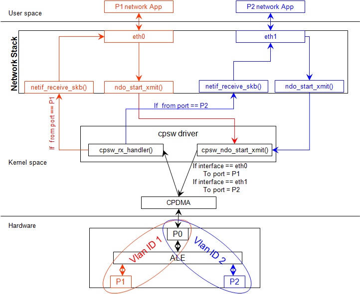
Assumptions
- Interrupt source is common for both eth interfaces
- CPDMA and skb buffers are common for both eth interfaces
- If eth0 is up, then eth0 napi is used. eth1 napi is used when eth0 interface is down
- CPSW and ALE will be in VLAN aware mode irrespective of enabling of 802.1Q module in Linux network stack for adding port VLAN.
- Interrupt pacing is common for both interfaces
- Hardware statistics is common for all the ports
- Switch config will not be available in dual emac interface mode
Constraints
The following are the constrains for Dual Emac mode implementation
- VLAN id 1 and 2 are reserved for EMAC 0 and 1 respectively for port segregation
- Port vlans mentioned in dts file are reserved and should not be added to cpsw through vconfig as it violate the Dual EMAC implementation and switch mode will be enabled.
- While adding VLAN id to the eth interfaces, same VLAN id should not be added in both interfaces which will lead to VLAN forwarding and act as switch
- Manual ip for eth1 is not supported from Linux kernel arguments
- Both the interfaces should not be connected to the same subnet unless only configuring bridging, and not doing IP routing, then you can configure the two interfaces on the same subnet.
Dual EMAC Device tree entry
Dual EMAC can be enabled with adding the entry dual_emac to the cpsw device tree node as the reference patch below
diff --git a/arch/arm/boot/dts/am335x-evmsk.dts b/arch/arm/boot/dts/am335x-evmsk.dts
index ac1f759..b50e9ef 100644
--- a/arch/arm/boot/dts/am335x-evmsk.dts
+++ b/arch/arm/boot/dts/am335x-evmsk.dts
@@ -473,6 +473,7 @@
        pinctrl-names = "default", "sleep";
        pinctrl-0 = <&cpsw_default>;
        pinctrl-1 = <&cpsw_sleep>;
+       dual_emac;
 };

 &davinci_mdio {
@@ -484,11 +485,13 @@
 &cpsw_emac0 {
        phy_id = <&davinci_mdio>, <0>;
        phy-mode = "rgmii-txid";
+       dual_emac_res_vlan = <1>;
 };

 &cpsw_emac1 {
        phy_id = <&davinci_mdio>, <1>;
        phy-mode = "rgmii-txid";
+       dual_emac_res_vlan = <2>;
 };
Bringing Up interfaces
Eth0 will be up by-default. Eth1 interface has to be brought up manually using either of the folloing command or through init scripts
DHCP
ifup eth1
Manual IP address configuration
ifconfig eth1 <ip> netmask <mask> up
Primary Interface on Second External Port
There are some pin mux configurations on devices that use the CPSW 3P such as the AM335x, AM437x, AM57x and others that to enable Ethernet requires using the second external port as the primary interface. Here is a suggested DTS configuration when using the second port.
The key step is setting the active_slave flag to 1 in the MAC node of the board DTS, this tells the driver to use the second interface as primary in a single MAC configuration. The cpsw1 relates to the physical port and not the Ethernet device. Also make sure to remove the dual mac flag. This example configuration will still yield eth0 in the network interface list.
Please note this is an example for the AM335x, the PHY mode below will set tx internal delay (rgmii-txid) which is required for AM335x devices. Please consult example DTS files for the AM437x and AM57x EVMs for respective PHY modes.
&mac {
       pinctrl-names = "default", "sleep";
       pinctrl-0 = <&cpsw_default>;
       pinctrl-1 = <&cpsw_sleep>;
       active_slave = <1>;
       status = "okay";
};

&davinci_mdio {
       pinctrl-names = "default", "sleep";
       pinctrl-0 = <&davinci_mdio_default>;
       pinctrl-1 = <&davinci_mdio_sleep>;
       status = "okay";
};

&cpsw_emac1 {
       phy_id = <&davinci_mdio>, <1>;
       phy-mode = "rgmii-txid";
};
Switch Configuration Interface
Introduction
The CPSW Ethernet Switch can be configured in various different combination of Ethernet Packet forwarding and blocking. There is no such standard interface in Linux to configure a switch. This user guide provides an interface to configure the switch using Socket IOCTL through SIOCSWITCHCONFIG command.
Configuring Kernel with VLAN Support
Userspace binary formats —>
    Power management options  --->
[*] Networking support  --->
    Device Drivers  --->
    File systems  --->
    Kernel hacking  --->
--- Networking support
      Networking options  --->
[ ]   Amateur Radio support  --->
<*>   CAN bus subsystem support  --->
< >   IrDA (infrared) subsystem support  --->
< >   Bluetooth subsystem support  --->
< >   RxRPC session sockets
< > The RDS Protocol (EXPERIMENTAL)
< > The TIPC Protocol (EXPERIMENTAL)  --->
< > Asynchronous Transfer Mode (ATM)
< > Layer Two Tunneling Protocol (L2TP)  --->
< > 802.1d Ethernet Bridging
[ ] Distributed Switch Architecture support  --->
<*> 802.1Q VLAN Support
[*]   GVRP (GARP VLAN Registration Protocol) support
< > DECnet Support
< > ANSI/IEEE 802.2 LLC type 2 Support
< > The IPX protocol
Switch Config Commands
Following is sample code for configuring the switch.
#include <stdio.h>
...
#include <linux/net_switch_config.h>
int main(void)
{
    struct net_switch_config cmd_struct;
    struct ifreq ifr;
    int sockfd;
    strncpy(ifr.ifr_name, "eth0", IFNAMSIZ);
    ifr.ifr_data = (char*)&cmd_struct;
    if ((sockfd = socket(AF_INET, SOCK_DGRAM, 0)) < 0) {
        printf("Can't open the socket\n");
        return -1;
    }
    memset(&cmd_struct, 0, sizeof(struct net_switch_config));

    ...//initialise cmd_struct with switch commands

    if (ioctl(sockfd, SIOCSWITCHCONFIG, &ifr) < 0) {
        printf("Command failed\n");
        close(sockfd);
        return -1;
    }
    printf("command success\n");
    close(sockfd);
    return 0;
}
CONFIG_SWITCH_ADD_MULTICAST
CONFIG_SWITCH_ADD_MULTICAST is used to add a LLDP Multicast address and forward the multicast packet to the subscribed ports. If VLAN ID is greater than zero then VLAN LLDP/Multicast is added.
cmd_struct.cmd = CONFIG_SWITCH_ADD_MULTICAST
| Parameter | Description | Range |
|---|---|---|
| cmd_struct.addr | LLDP/Multicast Address | MAC Address |
| cmd_struct.port | Member port | Bit 0 – Host port/Port 0 | Bit 1 – Slave 0/Port 1 | Bit 2 – Slave 1/Port 2 | 0 – 7 |
| cmd_struct.vid | VLAN ID | 0 – 4095 |
| cmd_struct.super | Super | 0/1 |
Result
ioctl call returns success or failure.
CONFIG_SWITCH_DEL_MULTICAST
CONFIG_SWITCH_DEL_MULTICAST is used to Delete a LLDP/Multicast address with or without VLAN ID.
cmd_struct.cmd = CONFIG_SWITCH_DEL_MULTICAST
| Parameter | Description | Range |
|---|---|---|
| cmd_struct.addr | Unicast Address | MAC Address |
| cmd_struct.vid | VLAN ID | 0 – 4095 |
Result
ioctl call returns success or failure.
CONFIG_SWITCH_ADD_VLAN
CONFIG_SWITCH_ADD_VLAN is used to add VLAN ID.
cmd_struct.cmd = CONFIG_SWITCH_ADD_VLAN
| Parameter | Description | Range |
|---|---|---|
| cmd_struct.vid | VLAN ID | 0 – 4095 |
| cmd_struct.port | Member port | Bit 0 – Host port/Port 0 | Bit 1 – Slave 0/Port 1 | Bit 2 – Slave 1/Port 2 | 0 – 7 |
| cmd_struct.untag_port | Untagged Egress port mask | Bit 0 – Host port/Port 0 | Bit 1 – Slave 0/Port 1 | Bit 2 – Slave 1/Port 2 | 0 – 7 |
| cmd_struct.reg_multi | Registered Multicast flood port mask | Bit 0 – Host port/Port 0 | Bit 1 – Slave 0/Port 1 | Bit 2 – Slave 1/Port 2 | 0 – 7 |
| cmd_struct.unreg_multi | Unknown Multicast flood port mask | Bit 0 – Host port/Port 0 | Bit 1 – Slave 0/Port 1 | Bit 2 – Slave 1/Port 2 | 0 – 7 |
Result
ioctl call returns success or failure.
CONFIG_SWITCH_DEL_VLAN
CONFIG_SWITCH_DEL_VLAN is used to delete VLAN ID.
cmd_struct.cmd = CONFIG_SWITCH_DEL_VLAN
| Parameter | Description | Range |
|---|---|---|
| cmd_struct.vid | VLAN ID | 0 – 4095 |
Result
ioctl call returns success or failure.
CONFIG_SWITCH_ADD_UNKNOWN_VLAN_INFO
CONFIG_SWITCH_ADD_UNKNOWN_VLAN_INFO is used to set unknown VLAN Info.
cmd_struct.cmd = CONFIG_SWITCH_ADD_UNKNOWN_VLAN_INFO
| Parameter | Description | Range |
|---|---|---|
| cmd_struct.unknown_vla n_member | Port mask | Bit 0 – Host port/Port 0 | Bit 1 – Slave 0/Port 1 | Bit 2 – Slave 1/Port 2 | 0 - 7 |
| cmd_struct.unknown_vla n_reg_multi | Registered Multicast flood port mask | Bit 0 – Host port/Port 0 | Bit 1 – Slave 0/Port 1 | Bit 2 – Slave 1/Port 2 | 0 - 7 |
| cmd_struct.unknown_vla n_unreg_multi | Unknown Multicast flood port mask | Bit 0 – Host port/Port 0 | Bit 1 – Slave 0/Port 1 | Bit 2 – Slave 1/Port 2 | 0 - 7 |
| cmd_struct.unknown_vla n_untag | Unknown Vlan Member port mask | Bit 0 – Host port/Port 0 | Bit 1 – Slave 0/Port 1 | Bit 2 – Slave 1/Port 2 | 0 - 7 |
Result
ioctl call returns success or failure.
CONFIG_SWITCH_SET_PORT_CONFIG
CONFIG_SWITCH_SET_PORT_CONFIG is used to set Phy Config.
cmd_struct.cmd = CONFIG_SWITCH_SET_PORT_CONFIG
| Parameter | Description | Range |
|---|---|---|
| cmd_struct.port | Port number | 0 - 2 |
| cmd_struct.ecmd | Phy settings | Fill this structure (struct ethtool_cmd), refer file include/uapi/linux/ethtool.h |
Result
ioctl call returns success or failure.
CONFIG_SWITCH_GET_PORT_CONFIG
CONFIG_SWITCH_GET_PORT_CONFIG is used to get Phy Config.
cmd_struct.cmd = CONFIG_SWITCH_GET_PORT_CONFIG
| Parameter | Description | Range |
|---|---|---|
| cmd_struct.port | Port number | 0 - 2 |
Result
ioctl call returns success or failure.
On success “cmd_struct.ecmd” holds port phy settings
CONFIG_SWITCH_SET_PORT_STATE
CONFIG_SWITCH_SET_PORT_STATE is used to set port status.
cmd_struct.cmd = CONFIG_SWITCH_SET_PORT_STATE
| Parameter | Description | Range |
|---|---|---|
| cmd_struct.port | Port number | 0 - 2 |
| cmd_struct.port_state | Port state | PORT_STATE_DISABLED/ PORT_STATE_BLOCKED/ PORT_STATE_LEARN/ PORT_STATE_FORWARD |
Result
ioctl call returns success or failure.
CONFIG_SWITCH_GET_PORT_STATE
CONFIG_SWITCH_GET_PORT_STATE is used to set port status.
cmd_struct.cmd = CONFIG_SWITCH_GET_PORT_STATE
| Parameter | Description | Range |
|---|---|---|
| cmd_struct.port | Port number | 0 - 2 |
Result
ioctl call returns success or failure.
On success “cmd_struct.port_state” holds port state
CONFIG_SWITCH_RATELIMIT
CONFIG_SWITCH_RATELIMIT is used to enable/disable rate limit of the ports.
The MC/BC Rate limit feature filters of BC/MC packets per sec as following:
number_of_packets/sec = (Fclk / ALE_PRESCALE) * port.BCAST/MCAST_LIMIT
where: ALE_PRESCALE width is 19bit and min value 0x10.
Each ALE prescale pulse loads port.BCAST/MCAST_LIMIT into the port MC/BC rate limit counter and port counters are decremented with each packet received or transmitted depending on whether the mode is transmit or receive. ALE prescale pulse frequency detrmined by ALE_PRESCALE register.
with Fclk = 125MHz and port.BCAST/MCAST_LIMIT = 1
max number_of_packets/sec = (125MHz / 0x10) * 1 = 7 812 500
min number_of_packets/sec = (125MHz / 0xFFFFF) * 1 = 119
So port.BCAST/MCAST_LIMIT can be selected to be 1 while ALE_PRESCALE is calculated as:
ALE_PRESCALE = Fclk / number_of_packets
cmd\_struct.cmd = CONFIG\_SWITCH\_RATELIMIT
| Parameter | Description | Range |
|---|---|---|
| cmd_struct.direction | Transmit/Receive | Transmit - 1 Receive - 0 |
| cmd_struct.port | Port number | 0 - 2 |
| cmd_struct.bcast_rate_limit | Broadcast, No of Packet | number_of_packets/sec |
| cmd_struct.mcast_rate_limit | Multicast, No of Packet | number_of_packets/sec |
Result
ioctl call returns success or failure.
Switch config ioctl mapping with v3.2
This section is applicable only to whom are migrating from v3.2 to v3.14 for am335x.
| v3.2 ioctl | Method in v3.14 | Comments |
|---|---|---|
| CONFIG_SWITCH_ADD_MULTICAST | CONFIG_SWITCH_ADD_MULTICAST | |
| CONFIG_SWITCH_ADD_UNICAST | Deprecated | Not supported as switch can learn by ingress packet |
| CONFIG_SWITCH_ADD_OUI | Deprecated | |
| CONFIG_SWITCH_FIND_ADDR | Deprecated | Address can be searched via ethtool -d ethX or switch-config -d,--dump |
| CONFIG_SWITCH_DEL_MULTICAST | CONFIG_SWITCH_DEL_MULTICAST | |
| CONFIG_SWITCH_DEL_UNICAST | Deprecated | |
| CONFIG_SWITCH_ADD_VLAN | CONFIG_SWITCH_ADD_VLAN | |
| CONFIG_SWITCH_FIND_VLAN | Deprecated | Address can be searched via ethtool -d ethX or switch-config -d,--dump |
| CONFIG_SWITCH_DEL_VLAN | CONFIG_SWITCH_DEL_VLAN | |
| CONFIG_SWITCH_SET_PORT_VLAN_CONFIG | CONFIG_SWITCH_SET_PORT_VLAN_CONFIG | |
| CONFIG_SWITCH_TIMEOUT | Deprecated | There is no hardware timers, a software timer of 10S is used to clear untouched entries in ALE table. |
| CONFIG_SWITCH_DUMP | Deprecated | Address can be searched via ethtool -d ethX or switch-config -d,--dump |
| CONFIG_SWITCH_SET_FLOW_CONTROL | Deprecated | Address can be searched via ethtool -A ethX <parameters> |
| CONFIG_SWITCH_SET_PRIORITY_MAPPING | Deprecated | |
| CONFIG_SWITCH_PORT_STATISTICS_ENABLE | Deprecated | statistics is enabled for all ports by default |
| CONFIG_SWITCH_CONFIG_DUMP | Deprecated | Address can be searched via ethtool -S ethX |
| CONFIG_SWITCH_RATELIMIT | CONFIG_SWITCH_RATELIMIT | |
| CONFIG_SWITCH_VID_INGRESS_CHECK | Deprecated | |
| CONFIG_SWITCH_ADD_UNKNOWN_VLAN_INFO | CONFIG_SWITCH_ADD_UNKNOWN_VLAN_INFO | |
| CONFIG_SWITCH_802_1 | Deprecated | Can be achecived by adding respective multicast address using CONFIG_SWITCH_ADD_MULTICAST |
| CONFIG_SWITCH_MACAUTH | Deprecated | |
| CONFIG_SWITCH_SET_PORT_CONFIG | CONFIG_SWITCH_SET_PORT_CONFIG | |
| CONFIG_SWITCH_GET_PORT_CONFIG | CONFIG_SWITCH_GET_PORT_CONFIG | |
| CONFIG_SWITCH_PORT_STATE | CONFIG_SWITCH_GET_PORT_STATE/ CONFIG_SWITCH_SET_PORT_STATE | |
| CONFIG_SWITCH_RESET | Deprecated | Close the interface and open the interface again which will reset the switch by default. |
ethtool - Display or change ethernet card settings
ethtool DEVNAME Display standard information about device
# ethtool eth0
Settings for eth0:
Supported ports: [ TP MII ]
Supported link modes:   10baseT/Half 10baseT/Full
                        100baseT/Half 100baseT/Full
                        1000baseT/Half 1000baseT/Full
Supported pause frame use: Symmetric
Supports auto-negotiation: Yes
Advertised link modes:  10baseT/Half 10baseT/Full
                        100baseT/Half 100baseT/Full
                        1000baseT/Half 1000baseT/Full
Advertised pause frame use: Symmetric
Advertised auto-negotiation: Yes
Link partner advertised link modes:  10baseT/Half 10baseT/Full
                                     100baseT/Half 100baseT/Full
                                     1000baseT/Full
Link partner advertised pause frame use: Symmetric
Link partner advertised auto-negotiation: Yes
Speed: 1000Mb/s
Duplex: Full
Port: MII
PHYAD: 1
Transceiver: external
Auto-negotiation: on
Supports Wake-on: d
Wake-on: d
Current message level: 0x00000000 (0)
Link detected: yes"
ethtool -i|–driver DEVNAME Show driver information
#ethtool -i eth0
driver: cpsw
version: 1.0
firmware-version:
expansion-rom-version:
bus-info: 48484000.ethernet
supports-statistics: yes
supports-test: no
supports-eeprom-access: no
supports-register-dump: yes
supports-priv-flags: no"
ethtool -P|–show-permaddr DEVNAME Show permanent hardware address
# ethtool -P eth0
Permanent address: a0:f6:fd:a6:46:6e"
ethtool -s|–change DEVNAME Change generic options
Below commands will be redirected to the phy driver:
[ speed %d ]
[ duplex half|full ]
[ autoneg on|off ]
[ wol p|u|m|b|a|g|s|d... ]
[ sopass %x:%x:%x:%x:%x:%x ]
Note
CPSW driver do not perform any kind of WOL specific actions or configurations.
#ethtool -s eth0 duplex half speed 100
[ 3550.892112] cpsw 48484000.ethernet eth0: Link is Down
[ 3556.088704] cpsw 48484000.ethernet eth0: Link is Up - 100Mbps/Half - flow control off
Sets the driver message type flags by name or number
[ msglvl %d | msglvl type on|off ... ]
# ethtool -s eth0 msglvl drv off
# ethtool -s eth0 msglvl ifdown off
# ethtool -s eth0 msglvl ifup off
# ethtool eth0
Current message level: 0x00000031 (49)
                       drv ifdown ifup
ethtool -r|–negotiate DEVNAME Restart N-WAY negotiation
# ethtool -r eth0
[ 4338.167685] cpsw 48484000.ethernet eth0: Link is Down
[ 4341.288695] cpsw 48484000.ethernet eth0: Link is Up - 1Gbps/Full - flow control rx/tx"
ethtool -a|–show-pause DEVNAME Show pause options
# ethtool -a eth0
Pause parameters for eth0:
Autonegotiate:  off
RX:             off
TX:             off
ethtool -A|–pause DEVNAME Set pause options
# ethtool -A eth0 rx on tx on
cpsw 48484000.ethernet eth0: Link is Up - 1Gbps/Full - flow control rx/tx
# ethtool -a eth0
Pause parameters for eth0:
Autonegotiate:  off
RX:             on
TX:             on
ethtool -C|–coalesce DEVNAME Set coalesce options
[rx-usecs N]
See [“Interrupt Pacing”] section for more information”
# ethtool -C eth0 rx-usecs 500
ethtool -c|–show-coalesce DEVNAME Show coalesce options
# ethtool -c eth0
Coalesce parameters for eth0:
Adaptive RX: off  TX: off
stats-block-usecs: 0
sample-interval: 0
pkt-rate-low: 0
pkt-rate-high: 0
rx-usecs: 0
rx-frames: 0
rx-usecs-irq: 0
rx-frames-irq: 0
tx-usecs: 0
tx-frames: 0
tx-usecs-irq: 0
tx-frames-irq: 0
rx-usecs-low: 0
rx-frame-low: 0
tx-usecs-low: 0
tx-frame-low: 0
rx-usecs-high: 0
rx-frame-high: 0
tx-usecs-high: 0
Tx-frame-high: 0
ethtool -G|–set-ring DEVNAME Set RX/TX ring parameters
Supported options:
[ rx N ]
See [“Configure number of TX/RX descriptors”] section for more information
# ethtool -G eth0 rx 8000
ethtool -g|–show-ring DEVNAME Query RX/TX ring parameters
# ethtool -g eth0
Ring parameters for eth0:
Pre-set maximums:
RX:             8184
RX Mini:        0
RX Jumbo:       0
TX:             0
Current hardware settings:
RX:             8000
RX Mini:        0
RX Jumbo:       0
TX:             192
ethtool -d|–register-dump DEVNAME Do a register dump
This command will dump current ALE table
# ethtool -d eth0
Offset          Values
------          ------
0x0000:         00 00 00 00 00 00 02 20 05 00 05 05 14 00 00 00
0x0010:         ff ff 02 30 ff ff ff ff 01 00 00 00 da 74 02 30
0x0020:         b9 83 48 ea 00 00 00 00 00 00 00 20 07 00 00 07
0x0030:         14 00 00 00 00 01 02 30 01 00 00 5e 0c 00 00 00
0x0040:         33 33 01 30 01 00 00 00 00 00 00 00 00 00 01 20
0x0050:         03 00 03 03 0c 00 00 00 ff ff 01 30 ff ff ff ff
ethtool -S|–statistics DEVNAME Show adapter statistics
# ethtool -S eth0
NIC statistics:
   Good Rx Frames: 24
   Broadcast Rx Frames: 12
   Multicast Rx Frames: 4
   Pause Rx Frames: 0
   Rx CRC Errors: 0
   Rx Align/Code Errors: 0
   Oversize Rx Frames: 0
   Rx Jabbers: 0
   Undersize (Short) Rx Frames: 0
   Rx Fragments: 1
   Rx Octets: 4290
   Good Tx Frames: 379
   Broadcast Tx Frames: 144
   Multicast Tx Frames: 228
   Pause Tx Frames: 0
   Deferred Tx Frames: 0
   Collisions: 0
   Single Collision Tx Frames: 0
   Multiple Collision Tx Frames: 0
   Excessive Collisions: 0
   Late Collisions: 0
   Tx Underrun: 0
   Carrier Sense Errors: 0
   Tx Octets: 72498
   Rx + Tx 64 Octet Frames: 30
   Rx + Tx 65-127 Octet Frames: 218
   Rx + Tx 128-255 Octet Frames: 0
   Rx + Tx 256-511 Octet Frames: 155
   Rx + Tx 512-1023 Octet Frames: 0
   Rx + Tx 1024-Up Octet Frames: 0
   Net Octets: 76792
   Rx Start of Frame Overruns: 0
   Rx Middle of Frame Overruns: 0
   Rx DMA Overruns: 0
   Rx DMA chan 0: head_enqueue: 2
   Rx DMA chan 0: tail_enqueue: 12114
   Rx DMA chan 0: pad_enqueue: 0
   Rx DMA chan 0: misqueued: 0
   Rx DMA chan 0: desc_alloc_fail: 0
   Rx DMA chan 0: pad_alloc_fail: 0
   Rx DMA chan 0: runt_receive_buf: 0
   Rx DMA chan 0: runt_transmit_bu: 0
   Rx DMA chan 0: empty_dequeue: 0
   Rx DMA chan 0: busy_dequeue: 14
   Rx DMA chan 0: good_dequeue: 21
   Rx DMA chan 0: requeue: 1
   Rx DMA chan 0: teardown_dequeue: 4095
   Tx DMA chan 0: head_enqueue: 378
   Tx DMA chan 0: tail_enqueue: 1
   Tx DMA chan 0: pad_enqueue: 0
   Tx DMA chan 0: misqueued: 1
   Tx DMA chan 0: desc_alloc_fail: 0
   Tx DMA chan 0: pad_alloc_fail: 0
   Tx DMA chan 0: runt_receive_buf: 0
   Tx DMA chan 0: runt_transmit_bu: 26
   Tx DMA chan 0: empty_dequeue: 379
   Tx DMA chan 0: busy_dequeue: 0
   Tx DMA chan 0: good_dequeue: 379
   Tx DMA chan 0: requeue: 0
   Tx DMA chan 0: teardown_dequeue: 0"
ethtool –phy-statistics DEVNAME Show phy statistics
ethtool -T|–show-time-stamping DEVNAME Show time stamping capabilities.
Accessible when CPTS is enabled.
# ethtool -T eth0
Time stamping parameters for eth0:
Capabilities:
        hardware-transmit     (SOF_TIMESTAMPING_TX_HARDWARE)
        software-transmit     (SOF_TIMESTAMPING_TX_SOFTWARE)
        hardware-receive      (SOF_TIMESTAMPING_RX_HARDWARE)
        software-receive      (SOF_TIMESTAMPING_RX_SOFTWARE)
        software-system-clock (SOF_TIMESTAMPING_SOFTWARE)
        hardware-raw-clock    (SOF_TIMESTAMPING_RAW_HARDWARE)
PTP Hardware Clock: 0
Hardware Transmit Timestamp Modes:
        off                   (HWTSTAMP_TX_OFF)
        on                    (HWTSTAMP_TX_ON)
Hardware Receive Filter Modes:
        none                  (HWTSTAMP_FILTER_NONE)
        ptpv2-event           (HWTSTAMP_FILTER_PTP_V2_EVENT)"
ethtool -L|–set-channels DEVNAME Set Channels.
Supported options:
[ rx N ]
[ tx N ]
Allows to control number of channels driver is allowed to work with at cpdma level. The maximum number of channels is 8 for rx and 8 for tx. In dual_emac mode the h/w channels are shared between two interfaces and changing number on one interface changes number of channels on another.
# ethtool -L eth0 rx 6 tx 6
ethtool-l|–show-channels DEVNAME Query Channels
# ethtool -l eth0
Channel parameters for eth0:
Pre-set maximums:
RX:             8
TX:             8
Other:          0
Combined:       0
Current hardware settings:
RX:             6
TX:             6
Other:          0
Combined:       0
ethtool –show-eee DEVNAME Show EEE settings
#ethtool --show-eee eth0
EEE Settings for eth0:
        EEE status: not supported
ethtool –set-eee DEVNAME Set EEE settings.
Note
Full EEE is not supported in cpsw driver, but it enables reading and writing of EEE advertising settings in Ethernet PHY. This way one can disable advertising EEE for certain speeds.
Realtime Linux Kernel Network performance
The significant network throughput drop is observed on SMP platforms with RT kernel (ti-rt-linux-4.9.y). There are few possible ways to improve network throughput on RT:
1) assign network interrupts to only one CPU (both RX/TX IRQ can be assigned to CPUx, or RX can be assigne to CPU0 and TX to CPU1) using cpu affinity settings:
am57xx-evm:~# cat /proc/interrupts
353:     518675          0      CBAR 335 Level     48484000.ethernet
354:    1468516          0      CBAR 336 Level     48484000.ethernet
assign both handlers to CPU1:
am57xx-evm:~#echo 2 > /proc/irq/354/smp_affinity
am57xx-evm:~#echo 2 > /proc/irq/353/smp_affinity
before:
am57xx-evm:~# iperf -c 192.168.1.1 -w128K -d -i5 -t120 & cyclictest -n -m -Sp97 -q -D2m
    ------------------------------------------------------------
    Server listening on TCP port 5001
    TCP window size:  256 KByte (WARNING: requested  128 KByte)
    ------------------------------------------------------------
    ------------------------------------------------------------
    Client connecting to 192.168.1.1, TCP port 5001
    TCP window size:  256 KByte (WARNING: requested  128 KByte)
    ------------------------------------------------------------
    [  5]  0.0-120.0 sec  2.16 GBytes   154 Mbits/sec
    [  4]  0.0-120.0 sec  5.21 GBytes   373 Mbits/sec
    T: 0 ( 1074) P:97 I:1000 C: 120000 Min:      8 Act:    9 Avg:   17 Max:      53
    T: 1 ( 1075) P:97 I:1500 C:  79982 Min:      8 Act:    9 Avg:   17 Max:      60
after:
am57xx-evm:~# iperf -c 192.168.1.1 -w128K -d -i5 -t120 & cyclictest -n -m -Sp97 -q -D2m
    ------------------------------------------------------------
    Server listening on TCP port 5001
    TCP window size:  256 KByte (WARNING: requested  128 KByte)
    ------------------------------------------------------------
    ------------------------------------------------------------
    Client connecting to 192.168.1.1, TCP port 5001
    TCP window size:  256 KByte (WARNING: requested  128 KByte)
    ------------------------------------------------------------
    [  5] local 192.168.1.2 port 35270 connected with 192.168.1.1 port 5001
    [  4] local 192.168.1.2 port 5001 connected with 192.168.1.1 port 55703
    [ ID] Interval       Transfer     Bandwidth
    [  5]  0.0-120.0 sec  4.58 GBytes   328 Mbits/sec
    [  4]  0.0-120.0 sec  4.88 GBytes   349 Mbits/sec
    T: 0 ( 1080) P:97 I:1000 C: 120000 Min:      9 Act:    9 Avg:   17 Max:      38
    T: 1 ( 1081) P:97 I:1500 C:  79918 Min:      9 Act:   16 Avg:   14 Max:      37
2) make CPSW network interrupts handlers non threaded. This requires kernel modification as done in:
[drivers: net: cpsw: mark rx/tx irq as IRQF_NO_THREAD]
See allso public discussion:
https://www.spinics.net/lists/netdev/msg389697.html
after:
am57xx-evm:~# iperf -c 192.168.1.1 -w128K -d -i5 -t120 & cyclictest -n -m -Sp97 -q - D2m
    ------------------------------------------------------------
    Server listening on TCP port 5001
    TCP window size:  256 KByte (WARNING: requested  128 KByte)
    ------------------------------------------------------------
    ------------------------------------------------------------
    Client connecting to 192.168.1.1, TCP port 5001
    TCP window size:  256 KByte (WARNING: requested  128 KByte)
    ------------------------------------------------------------
    [  5] local 192.168.1.2 port 33310 connected with 192.168.1.1 port 5001
    [  4] local 192.168.1.2 port 5001 connected with 192.168.1.1 port 55704
    [ ID] Interval       Transfer     Bandwidth
    [  5]  0.0-120.0 sec  3.72 GBytes   266 Mbits/sec
    [  4]  0.0-120.0 sec  5.99 GBytes   429 Mbits/sec
    T: 0 ( 1083) P:97 I:1000 C: 120000 Min:      8 Act:    9 Avg:   15 Max:      39
    T: 1 ( 1084) P:97 I:1500 C:  79978 Min:      8 Act:   10 Avg:   17 Max:      39
3.3.4.13.2. Common Platform Time Sync (CPTS) module
The Common Platform Time Sync (CPTS) module is used to facilitate host control of time sync operations. It enables compliance with the IEEE 1588-2008 standard for a precision clock synchronization protocol.
The support for CPTS module can be enabled by Kconfig option CONFIG_TI_CPTS=y or through menuconfig tool. The PTP packet timestamping can be enabled only for one CPSW port.
When CPTS module is enabled it will exports a kernel interface for specific clock drivers and a PTP clock API user space interface and enable support for SIOCSHWTSTAMP and SIOCGHWTSTAMP socket ioctls. The PTP exposes the PHC as a character device with standardized ioctls which usially can be found at path:
/dev/ptp0
Supported PTP hardware clock functionality:
Basic clock operations
   - Set time
   - Get time
   - Shift the clock by a given offset atomically
   - Adjust clock frequency
Ancillary clock features
   - Time stamp external events
   NOTE. Current implementation supports ext events with max frequency 5HZ.
Supported parameters for SIOCSHWTSTAMP and SIOCGHWTSTAMP:
SIOCGHWTSTAMP
   hwtstamp_config.flags = 0
   hwtstamp_config.tx_type
       HWTSTAMP_TX_ON
       HWTSTAMP_TX_OFF
   hwtstamp_config.rx_filter
       HWTSTAMP_FILTER_PTP_V2_EVENT
       HWTSTAMP_FILTER_NONE
SIOCSHWTSTAMP
   hwtstamp_config.flags = 0
   hwtstamp_config.tx_type
       HWTSTAMP_TX_ON - enables hardware time stamping for outgoing packets
       HWTSTAMP_TX_OFF - no outgoing packet will need hardware time stamping
   hwtstamp_config.rx_filter
       HWTSTAMP_FILTER_NONE - time stamp no incoming packet at all
HWTSTAMP_FILTER_PTP_V2_L4_EVENT
HWTSTAMP_FILTER_PTP_V2_L4_SYNC
HWTSTAMP_FILTER_PTP_V2_L4_DELAY_REQ
HWTSTAMP_FILTER_PTP_V2_L2_EVENT
HWTSTAMP_FILTER_PTP_V2_L2_SYNC
HWTSTAMP_FILTER_PTP_V2_L2_DELAY_REQ
HWTSTAMP_FILTER_PTP_V2_EVENT
HWTSTAMP_FILTER_PTP_V2_SYNC
HWTSTAMP_FILTER_PTP_V2_DELAY_REQ
- all above filters will enable timestamping of incoming PTP v2/802.AS1
  packets, any layer, any kind of event packet
CPTS PTP packet timestamping default configuration when enabled (SIOCSHWTSTAMP):
CPSW SS CPSW_VLAN_LTYPE register:
TS_LTYPE2 = 0
    Time Sync LTYPE2 This is an Ethertype value to match for tx and rx time sync packets.
TS_LTYPE1 = 0x88F7 (ETH_P_1588)
    Time Sync LTYPE1 This is an ethertype value to match for tx and rx time sync packets.
Port registers: Pn_CONTROL Register:
Pn_TS_107 Port n Time Sync Destination IP Address 107 enable
                0 – disabled
Pn_TS_320 Port n Time Sync Destination Port Number 320 enable
                1 - Annex D (UDP/IPv4) time sync packet destination port
                number 320 (decimal) is enabled.
Pn_TS_319 Port n Time Sync Destination Port Number 319 enable
                1 - Annex D (UDP/IPv4) time sync packet destination port
                number 319 (decimal) is enabled.
Pn_TS_132 Port n Time Sync Destination IP Address 132 enable
                1 - Annex D (UDP/IPv4) time sync packet destination IP
                address number 132 (decimal) is enabled.
Pn_TS_131 - Port 1 Time Sync Destination IP Address 131 enable
                1 - Annex D (UDP/IPv4) time sync packet destination IP
                address number 131 (decimal) is enabled.
Pn_TS_130 Port n Time Sync Destination IP Address 130 enable
                1 - Annex D (UDP/IPv4) time sync packet destination IP
                address number 130 (decimal) is enabled.
Pn_TS_129 Port n Time Sync Destination IP Address 129 enable
                1 - Annex D (UDP/IPv4) time sync packet destination IP
                address number 129 (decimal) is enabled.
Pn_TS_TTL_NONZERO Port n Time Sync Time To Live Non-zero enable.
                1 = TTL may be any value.
Pn_TS_UNI_EN Port n Time Sync Unicast Enable
                0 – Unicast disabled
Pn_TS_ANNEX_F_EN Port n Time Sync Annex F enable
                1 – Annex F enabled
Pn_TS_ANNEX_E_EN Port n Time Sync Annex E enable
                0 – Annex E disabled
Pn_TS_ANNEX_D_EN Port n Time Sync Annex D enable
                1 - Annex D enabled RW 0x0
Pn_TS_LTYPE2_EN Port n Time Sync LTYPE 2 enable
                0 - disabled
Pn_TS_LTYPE1_EN Port n Time Sync LTYPE 1 enable
                1 - enabled
Pn_TS_TX_EN Port n Time Sync Transmit Enable
                1 - enabled (if HWTSTAMP_TX_ON)
Pn_TS_RX_EN Port n Time Sync Receive Enable
                1 - Port 1 Receive Time Sync enabled (if HWTSTAMP_FILTER_PTP_V2_X)
Pn_TS_SEQ_MTYPE Register:
Pn_TS_SEQ_ID_OFFSET = 0x1E
                Port n Time Sync Sequence ID Offset This is the number
                of octets that the sequence ID is offset in the tx and rx
                time sync message header. The minimum value is 6. RW 0x1E
Pn_TS_MSG_TYPE_EN = 0xF (Sync, Delay_Req, Pdelay_Req, and Pdelay_Resp.)
                Port n Time Sync Message Type Enable - Each bit in this
                field enables the corresponding message type in receive
                and transmit time sync messages (Bit 0 enables message type 0 etc.).
For more information about PTP clock API and Network timestamping see Linux kernel documentation Documentation/ptp/ptp.txt
include/uapi/linux/ptp_clock.h
Documentation/ABI/testing/sysfs-ptp
tools/testing/selftests/networking/timestamping/timestamping.c
Testing using ptp4l tool from linuxptp project
To check the ptp clock adjustment with PTP protocol, a PTP slave (client) and a PTP master (server) applications are needed to run on separate devices (EVM or PC). Open source application package linuxptp can be used as slave and as well as master. Hence TX timestamp generation can be delayed (especially with low speed links) the ptp4l “tx_timestamp_timeout” parameter need to be set for ptp4l to work.
- create file ptp.cfg with content as below:
[global]
tx_timestamp_timeout     400
- pass configuration file to ptp4l using “-f” option:
ptp4l -E -2 -H -i eth0 -l 6 -m -q -p /dev/ptp0 -f ptp.cfg
- Slave Side Examples
The following command can be used to run a ptp-over-L4 client on the evm in slave mode
./ptp4l -E -4 -H -i eth0 -s -l 7 -m -q -p /dev/ptp0
For ptp-over-L2 client, use the command
./ptp4l -E -2 -H -i eth0 -s -l 7 -m -q -p /dev/ptp0
- Master Side Examples
ptp4l can also be run in master mode. For example, the following command starts a ptp4l-over-L2 master on an EVM using hardware timestamping,
./ptp4l -E -2 -H -i eth0 -l 7 -m -q -p /dev/ptp0
On a Linux PC which does not supoort hardware timestamping, the following command starts a ptp4l-over-L2 master using software timestamping.
./ptp4l -E -2 -S -i eth0 -l 7 -m -q
Testing using testptp tool from Linux kernel
- get the ptp clock time
# testptp -g
clock time: 1493255613.608918429 or Thu Apr 27 01:13:33 2017
- query the ptp clock’s capabilities
# testptp -c
capabilities:
  1000000 maximum frequency adjustment (ppb)
  0 programmable alarms
  0 external time stamp channels
  0 programmable periodic signals
  0 pulse per second
  0 programmable pins
- Sanity testing of cpts ref frequency
Time difference between to testptp -g calls should be equal sleep time
# testptp -g && sleep 5 && testptp -g
clock time: 1493255884.565859901 or Thu Apr 27 01:18:04 2017
clock time: 1493255889.611065421 or Thu Apr 27 01:18:09 2017
- shift the ptp clock time by ‘val’ seconds
# testptp -g && testptp -t 100 && testptp -g
clock time: 1493256107.640649117 or Thu Apr 27 01:21:47 2017
time shift okay
clock time: 1493256207.678819093 or Thu Apr 27 01:23:27 2017
- set the ptp clock time to ‘val’ seconds
# testptp -g && testptp -T 1000000 && testptp -g
clock time: 1493256277.568238925 or Thu Apr 27 01:24:37 2017
set time okay
clock time: 100.018944504 or Thu Jan  1 00:01:40 1970
- adjust the ptp clock frequency by ‘val’ ppb
# testptp -g && testptp -f 1000000 && testptp -g
clock time: 151.347795184 or Thu Jan  1 00:02:31 1970
frequency adjustment okay
clock time: 151.386187454 or Thu Jan  1 00:02:31 1970
Example of using Time stamp external events on am335x
On am335x boards Timestamping of external events can be tested using testptp tool and PWM timer.
It’s required to rebuild kernel with below changes first:
- enable config option CONFIG_PWM_OMAP_DMTIMER=y
- declare support of HW_TS_PUSH inputs in DT “mac: ethernet@4a100000” node
mac: ethernet@4a100000 {
     ...
     cpts-ext-ts-inputs = <4>;
- add PWM nodes in board file;
pwm7: dmtimer-pwm {
        compatible = "ti,omap-dmtimer-pwm";
        ti,timers = <&timer7>;
        #pwm-cells = <3>;
};
- build and boot new Kernel
- enable Timer7 to trigger 1sec periodic pulses on CPTS HW4_TS_PUSH input pin:
# echo 1000000000 > /sys/class/pwm/pwmchip0/pwm0/period
# echo 500000000 > /sys/class/pwm/pwmchip0/pwm0/duty_cycle
# echo 1 > /sys/class/pwm/pwmchip0/pwm0/enable
- read ‘val’ external time stamp events using testptp tool
 # ./ptp/testptp -e 10 -i 3
external time stamp request okay
event index 3 at 1493259028.376600798
event index 3 at 1493259029.377170898
event index 3 at 1493259030.377741039
event index 3 at 1493259031.378311139
event index 3 at 1493259032.378881279
3.3.4.14. NetCP
Keystone Multicore Navigator consists of Packet DMA and Queue Management sub systems.
Introduction
The knav driver consists of 3 drivers
- knav packet DMA driver (drivers/soc/ti/knav_dma.c
- knav qmss queue driver (drivers/soc/ti/knav_qmss_queue.c
- knav qmss accumulator driver (driver/soc/ti/knav_qmss_queue.c
The driver configures the multicore navigator hardware and exposes APIs to allow development of specific drivers to support Ethernet and other device drivers on keystone SoC. The APIs allow user to allocate resources such as descriptor pools, descriptors, queues (general, qpend, accumulator etc) supported by the multicore navigator to implement specific device driver functions.The data structures and APIs are located at
- include/linux/soc/ti/knav_dma.h
- include/linux/soc/ti/knav_qmss.h
Driver Configuration
To enable/disable Navigator support, start the Linux Kernel Configuration tool:
$ make menuconfig
...
...
Remoteproc drivers  --->
Rpmsg drivers  ----
SOC (System On Chip) specific Drivers  --->
Select SOC (System On Chip) specific Drivers
...
...
<*>   Keystone Queue Manager Sub System
<*>   TI Keystone Navigator Packet DMA support
Select Keystone Queue Manager Sub System and TI Keystone Navigator Packet DMA support from the TI SoC drivers support menu
Device Tree Documentation
Please refer the below DT documentation in the source tree for DT bindings documentation
- knav dma: Documentation/devicetree/bindings/soc/ti/keystone-navigator-dma.txt
- knav qmss: Documentation/devicetree/bindings/soc/ti/keystone-navigator-qmss.txt
Network Driver
Netcp Core driver
The NetCP network driver consists of a core driver that registers net device with Linux Network core driver framework. It is designed to allow use of pluggable modules to add support of basic network driver functionality and hw accelerations. The specific module is written as a netcp module to the netcp module interface. The netcp core driver expects the pluggable modules to register with it using the netcp_register_module() API. It provides a set of ops in the netcp_module structure as part of the registration.
struct netcp_module {
        const char              *name;
        struct module           *owner;
        bool                    primary;
/* probe/remove: called once per NETCP instance */
int     (*probe)(struct netcp_device *netcp_device,
                struct device *device, struct device_node *node,
                void **inst_priv);
int     (*remove)(struct netcp_device *netcp_device, void *inst_priv);
        /* attach/release: called once per network interface */
        int     (*attach)(void *inst_priv, struct net_device *ndev,
                          struct device_node *node, void **intf_priv);
        int     (*release)(void *intf_priv);
        int     (*open)(void *intf_priv, struct net_device *ndev);
        int     (*close)(void *intf_priv, struct net_device *ndev);
        int     (*add_addr)(void *intf_priv, struct netcp_addr *naddr);
        int     (*del_addr)(void *intf_priv, struct netcp_addr *naddr);
        int     (*add_vid)(void *intf_priv, int vid);
        int     (*del_vid)(void *intf_priv, int vid);
        int     (*ioctl)(void *intf_priv, struct ifreq *req, int cmd);

        /* used internally */
        struct list_head        module_list;
        struct list_head        interface_list;
};
NetCP core module probes the netcp module using the probe() API and attach it to a specific network interface. Other APIs are provided to help implement the net device operations. primary bool indicates if it is a mandatory module or not. For example at a bare minimum, the GBE module is needed and will be marked as primary. Other modules are optional based on the requirement to support hw acceleration capabilities provided by the hardware. Core driver is located at drivers/net/ethernet/ti/netcp_core.c
Gigabit and 10 Gigabit Ethernet Switching System
There is a common Ethss driver developed to support all K2 SoCs and both GBE and XGE (10G). The driver make use of DT compatibility string to customize the driver for different variant of the hardware available on K2 devices. The driver is written as a netcp module and registers with the netcp core. The driver supports 4 port / n port (8 for K2E and 4 for K2L) / 2 port (XGE) switch subsystems available on the K2 SoCs.
SGMII
The SGMII driver code is at drivers/net/ethernet/ti/netcp_sgmii.c
The SGMII module on Keystone 2 devices can be configured to operate in various modes. The modes are as follows
mac mac autonegotiate
mac phy
mac mac forced
mac fiber
mac phy no mdio
The mode of operation can be decided through the device tree bindings. An example is shown below for K2HK SoC
gbe@90000 { /* ETHSS */
interfaces {
gbe0: interface-0 {
phys = <&serdes_lane0>;
slave-port = <0>;
link-interface = <1>;
phy-handle = <ðphy0>;
};
gbe1: interface-1 {
phys = <&serdes_lane1>;
slave-port = <1>;
link-interface = <1>;
phy-handle = <ðphy1>;
};
};
};
AS we can see in the above, the link-interface attribute must be appropriately changed to decide the mode of operation. The link-interface may appear under secondary-slave-ports which are ports on EVM going to edge connectors such as AMC
gbe@90000 { /* ETHSS */
          secondary-slave-ports {
                  port-2 {
                       phys = <&serdes_lane2>;
                       slave-port = <2>;
                       link-interface   = <2>;
                  };
                  port-3 {
                        phys = <&serdes_lane3>;
                        slave-port = <3>;
                        link-interface  = <2>;
                  };
          };
};
Note
66AK2E supports 8 Ethernet (SGMII) ports, 2 ports to the EVM PHYs, 2 ports to AMC connector, and 4 ports to RTM connector. To enable the rest Ethernet ports at AMC and RTM connectors, The example of modification to the DTS fiels are shown below:
1. Enable the SerDes1 and all lanes on both SerDes 66AK2E has two SerDes and 4 lanes each. The default configuration has only SerDes0 enabled. The 2nd SerDes (SerDes1) needs to be enabled in keystone-k2e-evm.dts file.
&gbe_serdes1 {
        status = "okay";
};
In keystone-k2e-netcp.dtsi:
serdes0_lane2: lane@2 {
        status          = "ok";
serdes0_lane3: lane@3 {
        status          = "ok";
serdes1_lane0: lane@0 {
        status          = "ok";
serdes1_lane1: lane@1 {
        status          = "ok";
serdes1_lane2: lane@2 {
        status          = "ok";
serdes1_lane3: lane@3 {
        status          = "ok";
2. Define Ethernet property and PHY handle in keystone-k2e-evm.dts. The following example is using Mistral AMC BoC and Mistral RTM BoC.
&mdio {
    status = "ok";
    ethphy2: ethernet-phy@2 {
        compatible = "marvell,88E1111", "ethernet-phy-ieee802.3-c22";
        reg = <2>;
    };
    ethphy3: ethernet-phy@3 {
        compatible = "marvell,88E1111", "ethernet-phy-ieee802.3-c22";
        reg = <3>;
    };
    ethphy4: ethernet-phy@4 {
        compatible = "marvell,88E1145", "ethernet-phy-ieee802.3-c22";
        reg = <4>;
    };
    ethphy5: ethernet-phy@5 {
        compatible = "marvell,88E1145", "ethernet-phy-ieee802.3-c22";
        reg = <5>;
    };
    ethphy6: ethernet-phy@6 {
        compatible = "marvell,88E1145", "ethernet-phy-ieee802.3-c22";
        reg = <6>;
    };
    ethphy7: ethernet-phy@7 {
        compatible = "marvell,88E1145", "ethernet-phy-ieee802.3-c22";
        reg = <7>;
    };
};
- Add DMA channels associated with the port in keystone-k2e-netcp.dtsi
  ti,navigator-dmas =     <&dma_gbe 0>,
                          <&dma_gbe 8>,
+                         <&dma_gbe 16>,
+                         <&dma_gbe 24>,
+                         <&dma_gbe 32>,
+                         <&dma_gbe 40>,
+                         <&dma_gbe 48>,
+                         <&dma_gbe 56>,
                          <&dma_gbe 0>,
  ti,navigator-dma-names = "netrx0",
                           "netrx1",
+                          "netrx2",
+                          "netrx3",
+                          "netrx4",
+                          "netrx5",
+                          "netrx6",
+                          "netrx7",
                           "nettx",
                           "netrx0-pa",
Note
When enabling the 4 PHYs on Mistral RTM BoC, the SGMII ports need to be configured in reverse order. That is, instead of SGMII4(ethphy4) connected to PHY0(gbe4) on the RTM BoC, it is connected to PHY3(gbe7).
link-interface = <1>;
phy-handle = <ðphy1>;
};
+ gbe2: interface-2 {
+ phys = <&serdes0_lane2>;
+ slave-port = <2>;
+ link-interface = <1>;
+ phy-handle = <ðphy2>;
+ };
+ gbe3: interface-3 {
+ phys = <&serdes0_lane3>;
+ slave-port = <3>;
+ link-interface = <1>;
+ phy-handle = <ðphy3>;
+ };
+ gbe4: interface-4 {
+ phys = <&serdes1_lane0>;
+ slave-port = <4>;
+ link-interface = <1>;
+ phy-handle = <ðphy7>;
+ };
+ gbe5: interface-5 {
+ phys = <&serdes1_lane1>;
+ slave-port = <5>;
+ link-interface = <1>;
+ phy-handle = <ðphy6>;
+ };
+ gbe6: interface-6 {
+ phys = <&serdes1_lane2>;
+ slave-port = <6>;
+ link-interface = <1>;
+ phy-handle = <ðphy5>;
+ };
+ gbe7: interface-7 {
+ phys = <&serdes1_lane3>;
+ slave-port = <7>;
+ link-interface = <1>;
+ phy-handle = <ðphy4>;
+ };
};
5. The definition of secondary-slave-ports are not needed and should be removed
/*****
                       secondary-slave-ports {
                               port-2 {
                                       slave-port = <2>;
                                       link-interface  = <2>;
                               };
                               port-3 {
                                       slave-port = <3>;
                                       link-interface  = <2>;
                               };
                               port-4 {
                                       slave-port = <4>;
                                       link-interface  = <2>;
                               };
                               port-5 {
                                       slave-port = <5>;
                                       link-interface  = <2>;
                               };
                               port-6 {
                                       slave-port = <6>;
                                       link-interface  = <2>;
                               };
                               port-7 {
                                       slave-port = <7>;
                                       link-interface  = <2>;
                               };
                       };
*****/
- Configure PA for each interface
                                        slave-port      = <1>;
                                        rx-channel      = "netrx1-pa";
                                };
+                                pa2: interface-2 {
+                                        slave-port      = <2>;
+                                        rx-channel      = "netrx2-pa";
+                                };
+
+                                pa3: interface-3 {
+                                        slave-port      = <3>;
+                                        rx-channel      = "netrx3-pa";
+                                };
+                                pa4: interface-4 {
+                                        slave-port      = <4>;
+                                        rx-channel      = "netrx4-pa";
+                                };
+
+                                pa5: interface-5 {
+                                        slave-port      = <5>;
+                                        rx-channel      = "netrx5-pa";
+                                };
+                                pa6: interface-6 {
+                                        slave-port      = <6>;
+                                        rx-channel      = "netrx6-pa";
+                                };
+
+                                pa7: interface-7 {
+                                        slave-port      = <7>;
+                                        rx-channel      = "netrx7-pa";
+                                };
                        };
Note
It is required that queues be contiguous on the rx side, so rx-queue for gbe and xge need to be reassigned.
                                   64 12 17 17
                                   64 12 17 17
                                   64 12 17 17>;
-                       tx-completion-queue = <530>;
+                       tx-completion-queue = <536>;
                        efuse-mac = <1>;
                        netcp-gbe = <&gbe0>;
                        netcp-pa2 = <&pa0>;
                        netcp-qos = <&qos0>;
                };
+                interface-1 {
+                        rx-channel = "netrx1";
+                        rx-pool = <1024 12>;
+                        rx-queue-depth = <128 128 0 0>;
+                        rx-buffer-size = <1518 4096 0 0>;
+                        rx-queue = <529>;
+                        tx-pools = <1024 12 17 17
+                                    64 12 17 17
+                                    64 12 17 17
+                                    64 12 17 17
+                                    64 12 17 17
+                                    64 12 17 17
+                                    64 12 17 17>;
+                        tx-completion-queue = <537>;
+                        efuse-mac = <0>;
+                        local-mac-address = [02 18 31 7e 3e 00];
+                        netcp-gbe = <&gbe1>;
+                        netcp-pa2 = <&pa1>;
+                         netcp-qos = <&qos1>;
+                };
+                interface-2 {
+                        rx-channel = "netrx2";
+                        rx-pool = <1024 12>;
+                        rx-queue-depth = <128 128 0 0>;
+                        rx-buffer-size = <1518 4096 0 0>;
+                        rx-queue = <530>;
+                        tx-pools = <1024 12 17 17
+                                    64 12 17 17
+                                    64 12 17 17
+                                    64 12 17 17
+                                    64 12 17 17
+                                    64 12 17 17
+                                    64 12 17 17>;
+                        tx-completion-queue = <538>;
+                        efuse-mac = <0>;
+                        netcp-gbe = <&gbe2>;
+                        netcp-pa2 = <&pa2>;
+                };
+               interface-3 {
+                       rx-channel = "netrx3";
+                        rx-pool = <1024 12>;
+                        rx-queue-depth = <128 128 0 0>;
+                        rx-buffer-size = <1518 4096 0 0>;
+                        rx-queue = <531>;
+                        tx-pools = <1024 12 17 17
+                                    64 12 17 17
+                                    64 12 17 17
+                                    64 12 17 17
+                                    64 12 17 17
+                                    64 12 17 17
+                                    64 12 17 17>;
+                       tx-completion-queue = <539>;
+                       efuse-mac = <0>;
+                       netcp-gbe = <&gbe3>;
+                       netcp-pa2 = <&pa3>;
+                };
+                interface-4 {
+                        rx-channel = "netrx4";
+                        rx-pool = <1024 12>; /* num_desc region-id */
+                        rx-queue-depth = <128 128 0 0>;
+                        rx-buffer-size = <1518 4096 0 0>;
+                        rx-queue = <532>;
+                        /* 7 pools, hence 7 subqueues
+                         *   <#desc rgn-id tx-thresh rx-thresh>
+                         */
+                        tx-pools = <1024 12 17 17
+                                    64 12 17 17
+                                    64 12 17 17
+                                    64 12 17 17
+                                    64 12 17 17
+                                    64 12 17 17
+                                    64 12 17 17>;
+                        tx-completion-queue = <540>;
+                        efuse-mac = <0>;
+                        netcp-gbe = <&gbe4>;
+                        netcp-pa2 = <&pa4>;
+                };
+                interface-5 {
+                        rx-channel = "netrx5";
+                        rx-pool = <1024 12>; /* num_desc region-id */
+                        rx-queue-depth = <128 128 0 0>;
+                        rx-buffer-size = <1518 4096 0 0>;
+                        rx-queue = <533>;
+                        /* 7 pools, hence 7 subqueues
+                         *   <#desc rgn-id tx-thresh rx-thresh>
+                         */
+                        tx-pools = <1024 12 17 17
+                                    64 12 17 17
+                                    64 12 17 17
+                                    64 12 17 17
+                                    64 12 17 17
+                                    64 12 17 17
+                                    64 12 17 17>;
+                        tx-completion-queue = <541>;
+                        efuse-mac = <0>;
+                        netcp-gbe = <&gbe5>;
+                        netcp-pa2 = <&pa5>;
+                };
+                interface-6 {
+                        rx-channel = "netrx6";
+                        rx-pool = <1024 12>; /* num_desc region-id */
+                        rx-queue-depth = <128 128 0 0>;
+                        rx-buffer-size = <1518 4096 0 0>;
+                        rx-queue = <534>;
+                        /* 7 pools, hence 7 subqueues
+                         *   <#desc rgn-id tx-thresh rx-thresh>
+                         */
+                        tx-pools = <1024 12 17 17
+                                    64 12 17 17
+                                    64 12 17 17
+                                    64 12 17 17
+                                    64 12 17 17
+                                    64 12 17 17
+                                    64 12 17 17>;
+                        tx-completion-queue = <542>;
+                        efuse-mac = <0>;
+                        netcp-gbe = <&gbe6>;
+                        netcp-pa2 = <&pa6>;
+                };
+                interface-7 {
+                        rx-channel = "netrx7";
+                        rx-pool = <1024 12>; /* num_desc region-id */
+                        rx-queue-depth = <128 128 0 0>;
+                        rx-buffer-size = <1518 4096 0 0>;
+                        rx-queue = <535>;
+                        /* 7 pools, hence 7 subqueues
+                         *   <#desc rgn-id tx-thresh rx-thresh>
+                         */
+                        tx-pools = <1024 12 17 17
+                                    64 12 17 17
+                                    64 12 17 17
+                                    64 12 17 17
+                                    64 12 17 17
+                                    64 12 17 17
+                                    64 12 17 17>;
+                        tx-completion-queue = <543>;
+                        efuse-mac = <0>;
+                        netcp-gbe = <&gbe7>;
+                        netcp-pa2 = <&pa7>;
+                };
        };
netcpx: netcp@2f00000 {
                        tx-pool = <1024 12>; /* num_desc region-id */
                        rx-queue-depth = <1024 1024 0 0>;
                        rx-buffer-size = <1536 4096 0 0>;
-                       rx-queue = <532>;
-                       tx-completion-queue = <534>;
+                       rx-queue = <544>;
+                       tx-completion-queue = <546>;
                        efuse-mac = <0>;
                        netcp-xgbe = <&xgbe0>;

netcpx: netcp@2f00000 {
                        tx-pool = <1024 12>; /* num_desc region-id */
                        rx-queue-depth = <1024 1024 0 0>;
                        rx-buffer-size = <1536 4096 0 0>;
-                       rx-queue = <533>;
-                       tx-completion-queue = <535>;
+                       rx-queue = <545>;
+                       tx-completion-queue = <547>;
                        efuse-mac = <0>;
                        netcp-xgbe = <&xgbe1>;
                };
XGMII & RGMII
The netcp DT binding uses link-interface property to indicate interface types for XGMII for XGBE (10G) and RGMII for NetCP lite (K2G SoC) as well.
Please see kernel source tree DT documentation at Documentation/devicetree/bindings/net/keystone-netcp.txt values to be used
Mark_mcast_match Special Packet Processing Feature
This feature provide for special packet egress processing for specific marked packets. The intended use is:
1) SOC Configured in multiple-interface mode
2) CPSW ALE re-enabled via /sys/class/net/eth0/device/ale_control (so that SOC switch is
   active behind the scenes)
3) NetCP interfaces slaved to a bridge
4) NetCP interfaces feed a common QoS tree
5) Bridge forwarding disabled via "ebtables -P FORWARD DROP" (because CPSW is
   doing the port to port forwarding)
In this rather odd situation, the bridge will transmit locally generated multicast (and broadcast) packets by sending one on each of the slaved interfaces (i.e. bridge flooding). This has two ramifications:
(a) This results in multiple packets (copies of these locally generated
    muliticasts) through a common QoS, which is considered "bad"
    because the common QOS tree is configured assuming only one copy.
(b) even if QOS is not present, sending multiple copies of these multicasts is
    sub-optimal since the CPSW switch is capable of doing the forwarding itself given
    just one copy of the original packet.
To avoid these ramifications, such local multicast packets can be marked via ebtables for special processing in the NetCP PA module before the packets are queued for transmission. Packets thus recognized are NOT marked for egress via a specific slave port, and thus will be transmitted through all slave ports by the CPSW h/w forwarding logic.
To do this, a new DTS parameter “mark_mcast_match” has been added. This parameter takes two u32 values: a “match” value and a “mask” value.
When the NetCP PA module encounters a packet with a non-zero skb->mark field, it bitwise-ANDs the skb->mark value with the “mask” value and then compares the result with the “match” value. If these do not match, the mark is ignored and the packet is processed normally.
However, if the “match” value matches, then the low-order 8 bits of the skb->mark field is used as a bitmask to determine whether the packet should be dropped. If the packet would normally have been directed to slave port 1, then bit 0 of skb->mark is checked; slave port 2 checks bit 1, etc. If the bit is set, then the packet is enqueued for ALE processing but with the CPSW engress port field in the descriptor set to 0 (indicating that CPSW is responsible for selecting the egress port(s) to forward the packet too) ; if the bit is NOT set, the packet is silently dropped.
An example...
The device tree contains this PA definition:
mark_mcast_match = <0x12345a00 0xffffff00>;
The runtime configuration scripts execute this command:
ebtables -A OUTPUT -d Multicast -j mark \ –mark-set 0x12345a01 –mark-target ACCEPT
When the bridge attempts to send an ARP (broadcast) packet, it will send one packet to each of the slave interfaces. The packet sent by the bridge to slave interface eth0 (CPSW slave port 1) will be passed to the CPSW, and the ALE will broadcast this packet on all slave ports. The packets sent by the bridge to other slave interfaces (eth1, CPSW slave port 2) will be silently dropped.
Common Platform Time Sync (CPTS)
The Common Platform Time Sync (CPTS) module is used to facilitate host control of time sync operations. It enables compliance with the IEEE 1588-2008 standard for a precision clock synchronization protocol.
Although CPTS timestamping co-exists with PA timestamping, CPTS timestamping is only for PTP packets and in that case, PA will not timestamp those packets.
CPTS Hardware Configurations
1. CPTS Device Tree Bindings Following are the CPTS related device tree bindings
- cpts_reg_ofs
cpts register offset in cpsw module
- cpts_rftclk_sel
chooses the input rftclk, default is 0
- cpts_rftclk_freq
ref clock frequency in Hz if it is an external clock
- cpsw_cpts_rft_clk
ref clock name if it is an internal clock
- cpts_ts_comp_length
PPS Asserted Length (in Ref Clk Cycles)
- cpts_ts_comp_polarity
if 1, PPS is assered high; otherwise asserted low
- cpts_clock_mult, cpts_clock_shift, cpts_clock_div
multiplier and divider for converting cpts counter value to timestamp time
Example:
netcp: netcp@2090000 {
   ...
   clocks = <&papllclk>, <&clkcpgmac>, <&chipclk12>;
   clock-names = "clk_pa", "clk_cpgmac", "cpsw_cpts_rft_clk";
   ...
   cpsw: cpsw@2090000 {
   ...
      cpts_reg_ofs = <0xd00>;
      ...
      cpts_rftclk_sel=<8>;
      /*cpts_rftclk_freq = <122800000>;*/
      cpts_ts_comp_length = <3>;
      cpts_ts_comp_polarity = <1>;  /* 1 - assert high */
      /* cpts_clock_mult = <6250>; */
      /* cpts_clock_shift = <8>; */
      /* cpts_clock_div = <3>; */
      ...
   };
   ...
};
By default, cpts is configured with the following configurations at boot up:
- Tx and Rx Annex D support but only one vlan tag (ts_vlan_ltype1_en)
- Tx and Rx Annex E support but only one vlan tag (ts_vlan_ltype1_en)
- Tx and Rx Annex F support but only one vlan tag (ts_vlan_ltype1_en)
- ts_vlan_ltype1 = 0x8100 (default)
- uni-cast enabled
- ttl_nonzero enabled
Currently the following sysfs are available for cpts related runtime configuration
- /sys/devices/soc.0/2090000.netcp/cpsw/port_ts/n/uni_en
(where n is slave port number)
- Read/Write
- 1 (enable unicast)
- 0 (disable unicast)
- /sys/devices/soc.0/2090000.netcp/cpsw/port_ts/n/mcast_addr
(where n is slave port number)
- Read/Write
- bit map for mcast addr .132 .131 .130 .129 .107
- bit[4]: 224.0.1.132
- bit[3]: 224.0.1.131
- bit[2]: 224.0.1.130
- bit[1]: 224.0.1.129
- bit[0]: 224.0.0.107
- /sys/devices/soc.0/2090000.netcp/cpsw/port_ts/n/config
(where n is slave port number)
- Read Only
- shows the raw values of the cpsw port ts register configurations
Examples:
1. Checking whether uni-cast enabled
   $ cat /sys/devices/soc.0/2090000.netcp/cpsw/port_ts/1/uni_en
   $ 0
2. Enabling uni-cast
   $ echo 1 > /sys/devices/soc.0/2090000.netcp/cpsw/port_ts/1/uni_en
3. Checking which multi-cast addr is enabled (when uni_en=0)
   $ cat /sys/devices/soc.0/2090000.netcp/cpsw/port_ts/1/mcast_addr
   $ 0x1f
4. Disabling 224.0.1.131 and 224.0.0.107 but enabling the rest (when uni_en=0)
   $ echo 0x16 > /sys/devices/soc.0/2090000.netcp/cpsw/port_ts/1/mcast_addr
5. Showing the current port time sync config
   $ cat /sys/devices/soc.0/2090000.netcp/cpsw/port_ts/1/config
   000f06bb 001e88f7 81008100 01a088f7 00040000
where the displayed hex values correspond to the port registers
ts_ctl, ts_seq_ltype, ts_vlan_ltype, ts_ctl_ltype2 and ts_ctl2
Note 1: Although the above configurations are done through command line, they can also be done by using standard Linux open()/read()/write() file function calls.
Note 2: When uni-cast is enabled, ie. uni_en=1, mcast_addr configuration will not take effect since uni-cast will allow any uni-cast and multi-cast address.
CPTS Driver Internals Overview
1. Driver Initialization
On start up, the cpts driver
- initializes the input clock if it is an internal clock:
- enable the input clock
- get the clock frequency
- gets the frequency configuration of the input clock from the device tree bindings if it is an external clock
- selects/calculates (see Notes below for details) the multiplier (M), shift (S) and divisor (D) corresponding to the frequency for internal usage, ie. converting counter cycles to nsec by using the formula
nsec = ((cycles * M) >> S) / D
- gets the cpts_rftclk_sel value and program the CPTS RFTCLK_SEL register.
- configures the cpsw Px_TS_CTL, Px_TS_SEQ_LTYPE, Px_TS_VLAN_LTYPE, Px_TS_CTL_LTYPE2 and Px_TS_CTL2 registers (see section Configurations)
- registers itself to the Linux kernel ptp layer as a clock source (doing so makes sure the Linux kernel ptp layer and standard user space API’s can be used)
- mark the currnet cpts counter value to the current system time
- schedule a periodic work to catch the cpts counter overflow events and updates the driver’s internal time counter and cycle counter values accordingly.
For example, if F = 614400000, to find M/S/D such that
1000000000 = 614400000 * M / (2^S * D) simplify and rewrite both sides so that
2^4 * 5^4 = 2^11 * 3 * M / (2^S * D) or
M / (2^S * D) = 5000 / (2^10 * 3) hence
M = 5000, S = 10, D = 3 |
Note 3: cpts driver keeps a table of M/S/D for some common frequencies
| Freq (Hz) | M | S | D |
| 400000000 | 2560 | 10 | 1 |
| 425000000 | 5120 | 7 | 17 |
| 500000000 | 2048 | 10 | 1 |
| 600000000 | 5120 | 10 | 3 |
| 614400000 | 5000 | 10 | 3 |
| 625000000 | 4096 | 9 | 5 |
| 675000000 | 5120 | 7 | 27 |
| 700000000 | 5120 | 9 | 7 |
| 750000000 | 4096 | 10 | 3 |
Note 4: At start up, cpts driver selects or calculates the M/S/D for the rftclk frequency according to the following
- if M/S/D is defined in devicetree bindings, use them; otherwise
- if the rftclk frequency matches one of the frequencies in the table above, select the corresponding M/S/D; otherwise
- if the rftclk frequency differs from one of the frequencies in the table above by less than 1 MHz, select the M/S/D that corresponds to the frequency with the minimum difference; otherwise
- call clocks_calc_mult_shift( ) to calculate the M & S and set D = 1
In the tx direction during runtime, the driver
- marks the submitted packet to be CPTS timestamped if the the packet passes the PTP filter rules
- retrieves the timestamp on the transmitted ptp packet (packets submitted to a socket with proper socket configurations, see below) from CPTS’s event FIFO
- converts the counter value to nsec (recall the internal time counter and the cycle counter kept internally by the driver)
- packs the retrieved timestamp with a clone of the transmitted packet in a buffer
- returns the buffer to the app which submits the packet for transmission through the socket’s error queue
In the rx direction during runtime, the driver
- examines the received packet to see if it matches the PTP filter requirements
- if it does, then it retrieves the timestamp on the received ptp packet from the CPTS’s event FIFO
- coverts the counter value to nsec (recall the internal time counter and the cycle counter kept internally by the driver)
- packs the retrieved timestamp with received packet in a buffer
- pass the packet buffer onwards
Using CPTS Timestamping
CPTS user applications use standard Linux APIs to send and receive PTP packets, and to adjust CPTS clock.
User application sends and receives L4 PTP messages by calling Linux standard socket API functions
Example (see Reference i):
a. open UDP socket
b. call ioctl(sock, SIOCHWTSTAMP, ...) to set the hw timestamping
   socket config
c. bind to PTP event port
d. set dst address to socket
d. setsockopt to join multicast group (if using multicast)
f. setsockopt to set socket option SO_TIMESTAMP
g. sendto to send PTP packets
h. recvmsg( ... MSG_ERRQUEUE ...) to receive timestamped packets
User application sends and receives PTP messages over Ethernet by opening Linux RAW sockets.
Example (see file raw.c in Reference iii):
int fd
fd = socket(PF_PACKET, SOCK_RAW, htons(ETH_P_ALL));
...
In this case, PTP messages are encapsulated directly in Ethernet frames with EtherType 0x88f7.
When sending L2/L4 PTP messages over VLAN, step b in above example need to be applied to the actual interface instead of the VLAN interface.
Example (see Reference i):
Suppose a VLAN interface with vid=10 is added to the eth0 interface.
$ vconfig add eth0 10
$ ifconfig eth0.10 192.168.1.200
$ ifconfig
eth0      Link encap:Ethernet  HWaddr 00:17:EA:F4:32:3A
          inet addr:132.168.138.88  Bcast:0.0.0.0  Mask:255.255.254.0
          UP BROADCAST RUNNING MULTICAST  MTU:1500  Metric:1
          RX packets:647798 errors:0 dropped:158648 overruns:0 frame:0
          TX packets:1678 errors:0 dropped:0 overruns:0 carrier:0
          collisions:0 txqueuelen:1000
          RX bytes:58765374 (56.0 MiB)  TX bytes:84321 (82.3 KiB)
eth0.10   Link encap:Ethernet  HWaddr 00:17:EA:F4:32:3A
          inet addr:192.168.1.200  Bcast:192.168.1.255  Mask:255.255.255.0
          inet6 addr: fe80::217:eaff:fef4:323a/64 Scope:Link
          UP BROADCAST RUNNING MULTICAST  MTU:1500  Metric:1
          RX packets:6 errors:0 dropped:0 overruns:0 frame:0
          TX packets:61 errors:0 dropped:0 overruns:0 carrier:0
          collisions:0 txqueuelen:0
          RX bytes:836 (836.0 B)  TX bytes:6270 (6.1 KiB)
To enable hw timestamping on the eth0.10 interface, the ioctl(sock, SIOCHWTSTAMP, ...)
function call needs to be on the actual interface eth0:
int sock;
struct ifreq hwtstamp;
struct hwtstamp_config hwconfig;
...
sock = socket(PF_INET, SOCK_DGRAM, IPPROTO_UDP);
/* enable hw timestamping for interfaces eth0 or eth0.10 */
strncpy(hwtstamp.ifr_name, "eth0", sizeof(hwtstamp.ifr_name));
hwtstamp.ifr_data = (void *)&hwconfig;
memset(&hwconfig, 0, sizeof(hwconfig));
hwconfig.tx_type = HWTSTAMP_TX_ON
hwconfig.rx_filter = HWTSTAMP_FILTER_PTP_V1_L4_SYNC
ioctl(sock, SIOCSHWTSTAMP, &hwtstamp);
...
User application needs to inform the CPTS driver of any time or reference clock frequency adjustments, for example, as a result of running PTP protocol.
- It’s the application’s responsibility to modify the (physical) rftclk frequency.
- However, the frequency change needs to be sent to the cpts driver by calling the standard Linux API clock_adjtime() with a flag ADJ_FREQUENCY. This is needed so that the CPTS driver can calculate the time correctly.
- As indicated above, CPTS driver keeps a pair of numbers, the multiplier and divisor, to represent the reference clock frequency. When the frequency change API is called and passed with the ppb change, the CPTS driver updates its internal multiplier as follows:
new_mult = init_mult + init_mult * (ppb / 1000000000) Note: the ppb change is always applied to the initial orginal frequency, NOT the current frequency.
Example (see Reference ii):
struct timex tx;
...
fd = open("/dev/ptp0", O_RDWR);
clkid = get_clockid(fd);
...
memset(&tx, 0, sizeof(tx));
tx.modes = ADJ_FREQUENCY;
tx.freq = ppb_to_scaled_ppm(adjfreq);
if (clock_adjtime(clkid, &tx)) {
   perror("clock_adjtime");
} else {
   puts("frequency adjustment okay");
}
- To set time (due to shifting +/-), call the the standard Linux API clock_adjtime() with a flag ADJ_SETOFFSET
Example (see Reference ii):
memset(&tx, 0, sizeof(tx));
tx.modes = ADJ_SETOFFSET;
tx.time.tv_sec = adjtime;
tx.time.tv_usec = 0;
if (clock_adjtime(clkid, &tx) < 0) {
   perror("clock_adjtime");
} else {
   puts("time shift okay");
}
- To get time, call the the standard Linux API clock_gettime()
Example (see Reference ii):
if (clock_gettime(clkid, &ts)) {
   perror("clock_gettime");
} else {
   printf("clock time: %ld.%09ld or %s",
          ts.tv_sec, ts.tv_nsec, ctime(&ts.tv_sec));
}
- To set time, call the the standard Linux API clock_settime()
Example (see Reference ii):
clock_gettime(CLOCK_REALTIME, &ts);
if (clock_settime(clkid, &ts)) {
   perror("clock_settime");
} else {
   puts("set time okay");
}
Testing CPTS/PTP
To check the ptp clock adjustment with PTP protocol, a PTP slave (client) and a PTP master (server) applications are needed to run on separate devices (EVM or PC). Open source application package linuxptp (Reference iii) can be used as slave and as well as master. Another option for PTP master is the open source project ptpd (Reference iv).
- Slave Side Examples
The following command can be used to run a ptp-over-L4 client on the evm in slave mode
./ptp4l -E -4 -H -i eth0 -s -l 7 -m -q -p /dev/ptp0
For ptp-over-L2 client, use the command
./ptp4l -E -2 -H -i eth0 -s -l 7 -m -q -p /dev/ptp0
ptp4l runtime configuartions can be applied by saving desired configurations in a configuration file and start the ptp4l with an argument “-f <config_filename>” Note: Only ptp4l supports L2 ethernet, ptpd2 does not support L2. For example, put the following two lines
[global]
tx_timestamp_timeout  15
in a file named config, and start a ptp4l-over-L2 client with command
./ptp4l -E -2 -H -i eth0 -s -l 7 -m -q -p /dev/ptp0 -f config
the tx poll timeout interval will be set to 15 msec instead of the default 1 msec.
The adjusted time can be checked by cross compiling the testptp application from the linux kernel: Documentation/ptp/testptp.c. ( e.g) ./testptp -g
- Master Side Examples
ptp4l can also be run in master mode. For example, the following command starts a ptp4l-over-L2 master on an EVM using hardware timestamping,
./ptp4l -E -2 -H -i eth0 -l 7 -m -q -p /dev/ptp0 -f config
On a Linux PC which does not supoort hardware timestamping, the following command starts a ptp4l-over-L2 master using software timestamping.
./ptp4l -E -2 -S -i eth0 -l 7 -m -q -p -f config
Who Is Timestamping What?
Notice that PA timestamping and CPTS timestamping are running simultaneously. This is desirable in some use cases because, for example, NTP timestamping is also needed in some systems and CPTS timestamping is only for PTP. However, CPTS has priority over PA to timestamp PTP messages. When CPTS timestamps a PTP message, PA will not timestamp it. See the section PA Timestamping for more details about PA timestamping.
If needed, PA timestamping can be completely disabled by adding force_no_hwtstamp to the device tree.
Example:
pa: pa@2000000 {
        label = "keystone-pa";
        ...
        force_no_hwtstamp;
};
CPTS timestamping can be completely disabled by removing the following line from the device tree
cpts_reg_ofs = <0xd00>;
Pulse-Per-Second (PPS)
The CPTS driver uses the timestamp compare (TS_COMP) output to support PPS.
The TS_COMP output is asserted for ts_comp_length[15:0] RCLK periods when the time_stamp value compares with the ts_comp_val[31:0] and the length value is non-zero. The TS_COMP rising edge occurs three RCLK periods after the values compare. A timestamp compare event is pushed into the event FIFO when TS_COMP is asserted. The polarity of the TS_COMP output is determined by the ts_polarity bit. The output is asserted low when the polarity bit is low.
- The driver enables its pps support capability when it registers itself to the Linux PTP layer.
- Upon getting the pps support information from CPTS driver, the Linux PTP layer registers CPTS as a pps source with the Linux PPS layer. Doing so allows user applications to manage the PPS source by using Linux standard API.
- Upon CPTS pps being enabled by user application, the driver programs the TS_COMP_VAL for a pulse to be generated at the next (absolute) 1 second boundary. The TS_COMP_VAL to be programmed is calculated based on the reference clock frequency.
- Driver polls the CPTS event FIFO 5 times a second to retrieve the timestamp compare event of an asserted TS_COMP output signal.
- The driver reloads the TS_COMP_VAL register with a value equivalent to one second from the timestamp value of the retrieved event.
- The event is also reported to the Linux PTP layer which in turn reports to the PPS layer.
- Enabling CPTS PPS by using standard Linux ioctl PTP_ENABLE_PPS
Example (Reference ii: Documentation/ptp/testptp.c):
fd = open("/dev/ptp0", O_RDWR);
...
if (ioctl(fd, PTP_ENABLE_PPS, 1))
     perror("PTP_ENABLE_PPS");
else
     puts("pps for system time enable okay");
if (ioctl(fd, PTP_ENABLE_PPS, 0))
     perror("PTP_ENABLE_PPS");
else
     puts("pps for system time disable okay");
- Reading PPS last timstamp by using standard Linux ioctl PPS_FETCH
Example (Reference iii: linuxptp-1.2/phc2sys.c)
...
struct pps_fdata pfd;
pfd.timeout.sec = 10;
pfd.timeout.nsec = 0;
pfd.timeout.flags = ~PPS_TIME_INVALID;
if (ioctl(fd, PPS_FETCH, &pfd)) {
   pr_err("failed to fetch PPS: %m");
   return 0;
}
...
- Enabling PPS from sysfs
- The Linux PTP layer provides a sysfs for enabling/disabling PPS.
$ cat /sys/devices/soc.0/2090000.netcp/ptp/ptp0/pps_available
1
$ echo 1 > /sys/devices/soc.0/2090000.netcp/ptp/ptp0/pps_enable
- Sysfs Provided by Linux PPS Layer (see Reference v for more details)
- The Linux PPS layer implements a new class in the sysfs for supporting PPS.
$ ls /sys/class/pps/
pps0/
$
$ ls /sys/class/pps/pps0/
assert    clear  echo  mode  name  path  subsystem@  uevent
- Inside each “assert” you can find the timestamp and a sequence number:
$ cat /sys/class/pps/pps0/assert
1170026870.983207967#8
where before the "#" is the timestamp in seconds; after it is the sequence number.
4. Effects of Clock Adjustments on PPS
The user application calls the API functions clock_adjtime() or clock_settime() to inform the CPTS driver about any clock adjustment as a result of running the PTP protocol. The PPS may also need to be adjusted by the driver accordingly.
See Clock Adjustments in the CPTS User section for more details on clock adjustments.
- Shifting Time
The user application informs CPTS driver of the shifts the clock by calling clock_adjtime() with a flag ADJ_SETOFFSET. Shifting time may result in shifting the 1 second boundary. As such the driver recalculates the TS_COMP_VAL for the next pulse in order to align the pulse with the 1 second boundary after the shift.
Example 1. Positive Shift
Assuming a reference clock with freq = 100 Hz and the cpts counter is 1208
at the 10-th second (sec-10).
If no shifting happens, a pulse is asserted according to the following
      (abs)
cntr   sec    pulse
----   ---    -----
1208   10      ^
1308   11      ^
1408   12      ^
1508   13      ^
1608   14      ^
1708   15      ^
.
.
.
Suppose a shift of +0.25 sec occurs at cntr=1458
      (abs)
cntr   sec    pulse
----   ---    -----
1208   10      ^
1308   11      ^
1408   12      ^
1458   12.5                <- adjtime(ADJ_SETOFFSET, +0.25 sec)
1508   13
1608   14
1708   15
.
.
.
Instead of going out at cntr=1508 (which was sec-13 but is now sec-13.25 after
the shift), a pulse will go out at cntr=1583 (or sec-14) after the
re-alignment at the 1-second boundary.
      (abs)
cntr   sec    pulse
----   ---    -----
1208   10      ^
1308   11      ^
1408   12      ^
1458   12.75             (after +0.25 sec shift)
1483   13
1508   13.25             (realign orig pulse to cntr=1583)
1583   14      ^
1608   14.25
1683   15      ^
1708   15.25
.
.
.
Example 2. Negative Shift
Assuming a reference clock with freq = 100 Hz and the cpts counter is 1208
at the 10-th second (sec-10).
If no shifting happens, a pulse is asserted according to the following
      (abs)
cntr   sec    pulse
----   ---    -----
1208   10      ^
1308   11      ^
1408   12      ^
1508   13      ^
1608   14      ^
1708   15      ^
.
.
.
Suppose a shift of -3.25 sec occurs at cntr=1458
      (abs)
cntr   sec    pulse
----   ---    -----
1208   10      ^
1308   11      ^
1408   12      ^
1458   12.5                <- adjtime(ADJ_SETOFFSET, -3.25 sec)
1508   13
1608   14
1708   15
.
.
.
Instead of going out at cntr=1508 (which was sec-13 but is now sec-9.75
after the shift), a pulse will go out at cntr=1533 (or sec-10) after the
re-alignment at the 1-second boundary.
(abs)
cntr sec pulse
---- --- -----
1208 10 ^
1308 11 ^
1408 12 ^
1458 9.25 (after -3.25 sec shift)
1508 9.75 (realign orig pulse to cntr=1533)
1533 10 ^
1558 10.25
1608 10.75
1633 11 ^
1658 11.25
1708 11.75
.
.
.
Remark: If a second time shift is issued before the next re-aligned pulse is asserted after the first time shift, shifting of the next pulse can be accumulated.
Example 3. Accumulated Pulse Shift
Assuming a reference clock with freq = 100 Hz and the cpts counter is 1208
at the 10-th second (sec-10).
If no shifting happens, a pulse is asserted according to the following
(abs)
cntr sec pulse
---- --- -----
1208 10 ^
1308 11 ^
1408 12 ^
1508 13 ^
1608 14 ^
1708 15 ^
.
.
.
Suppose a shift of +0.25 sec occurs at cntr=1458
(abs)
cntr sec pulse
---- --- -----
1208 10 ^
1308 11 ^
1408 12 ^
1458 12.5 <- adjtime(ADJ_SETOFFSET, +0.25 sec)
1508 13
1608 14
1708 15
.
.
.
Instead of going out at cntr=1508 (which was sec-13 but is now sec-13.25 after
the shift), a pulse will go out at cntr=1583 (or sec-14) after the
re-alignment at the 1-second boundary.
(abs)
cntr sec pulse
---- --- -----
1208 10 ^
1308 11 ^
1408 12 ^
1458 12.75 (after +0.25 sec shift)
1483 13
1508 13.25 (realign orig pulse to cntr=1583)
1583 14 ^
1608 14.25
1683 15 ^
1708 15.25
.
.
.
Suppose another +0.25 sec time shift is issued at cntr=1533 before the
re-align pulse at cntr=1583 is asserted.
(abs)
cntr sec pulse
---- --- -----
1208 10 ^
1308 11 ^
1408 12 ^
1458 12.75
1483 13
1508 13.25
1533 13.5 <- adjtime(ADJ_SETOFFSET, +0.25 sec)
1583 14
1608 14.25
1683 15
1708 15.25
.
.
.
In this case the scheduled pulse at cntr=1583 is further shifted to cntr=1658.
(abs)
cntr sec pulse
---- --- -----
1208 10 ^
1308 11 ^
1408 12 ^
1458 12.75
1483 13
1508 13.25
1533 13.75 (after +0.25 sec shift)
1583 14.25
1608 14.5
1658 15 ^ (realign the cntr-1583-pulse to cntr=1658)
1683 15.25
1708 15.5
1758 16 ^
.
.
.
- Setting Time
The user application may set the internal timecounter kept by the CPTS driver by calling clock_settime(). Setting time may result in changing the 1-second boundary. As such the driver recalculates the TS_COMP_VAL for the next pulse in order to align the pulse with the 1 second boundary after the shift. The TS_COMP_VAL recalculation is similar to shifting time.
Example.
Assuming a reference clock with freq = 100 Hz and the cpts counter is 1208
at the 10-th second (sec-10).
If no time setting happens, a pulse is asserted according to the following
(abs)
cntr sec pulse
---- --- -----
1208 10 ^
1308 11 ^
1408 12 ^
1508 13 ^
1608 14 ^
1708 15 ^
.
.
.
Suppose at cntr=1458, time is set to 100.25 sec
(abs)
cntr sec pulse
---- --- -----
1208 10 ^
1308 11 ^
1408 12 ^
1458 12.5 <- settime(100.25 sec)
1508 13
1608 14
1708 15
.
.
.
Instead of going out at cntr=1508 (which was sec-13 but is now sec-100.75 after
the shift), a pulse will go out at cntr=1533 (or sec-101) after the
re-alignment at the 1-second boundary.
(abs)
cntr sec pulse
---- --- -----
1208 10 ^
1308 11 ^
1408 12 ^
1458 100.25 (after setting time to 100.25 sec)
1508 100.75 (realign orig pulse to cntr=1533)
1533 101 ^
1608 101.75
1633 102 ^
1708 102.75
1733 103 ^
.
.
.
- Changing Reference Clock Frequency
The user application informs the CPTS driver of the changes of the reference clock frequency by calling clock_adjtime() with a flag ADJ_FREQUENCY. In this case, the driver re-calculates the TS_COMP_VAL value for the next pulse, and the following pulses, based on the new frequency.
Example.
Assuming a reference clock with freq = 100 Hz and the cpts counter is 1208
at the 10-th second (sec-10).
If no time setting happens, a pulse is asserted according to the following
(abs)
cntr sec pulse
---- --- -----
1208 10 ^
1308 11 ^
1408 12 ^
1508 13 ^
1608 14 ^
1708 15 ^
.
.
.
Suppose at cntr=1458, reference clock freq is changed to 200Hz
*** Remark: The change to 200Hz is only for illustration. The
change should usually be parts-per-billion or ppb.
(abs)
cntr sec pulse
---- --- -----
1208 10 ^
1308 11 ^
1408 12 ^
1458 12.5 <- adjtime(ADJ_FREQUENCY, +100Hz)
1508 13
1608 14
1708 15
.
.
.
Instead of going out at cntr=1508 (which was sec-13 but is now sec-12.75 after
the freq change), a pulse will go out at cntr=1558 (or sec-13 in the new freq)
after the re-alignment at the 1-second boundary.
(abs)
cntr sec pulse
---- --- -----
1208 10 ^
1308 11 ^
1408 12 ^
1458 12.5 (after freq changed to 200Hz)
1508 12.75 (realign orig pulse to cntr=1558)
1558 13 ^
1608 13.25
1658 13.5
1708 13.75
1758 14 ^
.
.
.
CPTS Hardware Timestamp Push
There are eight hardware time stamp inputs (HW1/8_TS_PUSH) that can cause hardware time stamp push events to be loaded into the event FIFO. The CPTS driver supports the reporting of such timestamps by using the PTP EXTTS feature of the Linux PTP infrastructure.
Example (Reference ii: Documentation/ptp/testptp.c):
struct ptp_extts_event event;
struct ptp_extts_request extts_request;
/* which pin to get timestamp from, index is 0 based */
extts_request.index = 3;
extts_request.flags = PTP_ENABLE_FEATURE;
fd = open("/dev/ptp0", O_RDWR);
/* enabling */
ioctl(fd, PTP_EXTTS_REQUEST, &extts_request);
/* reading timestamps */
for (i=0; i < 10; i++) {
read(fd, &event, sizeof(event));
printf("event index %u at %lld.%09u\n", event.index,
event.t.sec, event.t.nsec);
}
/* disabling */
extts_request.flags = 0;
ioctl(fd, PTP_EXTTS_REQUEST, &extts_request);
Testing HW_TS_PUSH on Keystone2 (K2HK) EVM
Note: On K2HK EVM, only two HW_TS_PUSH pins are brought out. These are HW3_TS_PUSH and HW4_TS_PUSH. Refer to K2HK schematic for more details.
To use the TS_COMP_OUT signal to test HW_TS_PUSH:
- Connect jumper pins CN17-5 (TSCOMPOUT_E) and CN17-3 (TSPUSHEVt0)
- Connect pins CN3-114 (TSPUSHEVt0) and CN3-109 (TSPUSHEVt0_E). A ZX102-QSH 060-ST card is needed.
- Modify testptp.c to “extts_request.index = 3”, ie. reading timestamp from HW4_TS_PUSH pin
- Compile testptp
- Bootup K2HK Linux kernel
- Under Linux prompt, issue “echo 1 > /sys/devices/soc.0/2090000.netcp/ptp/ptp0/pps_enable” to generate TS_COMP_OUT signals.
- Under Linux prompt, issue ”./testptp -e 10” to read the HW4_TS_PUSH timestamps.
CPTS References
i. Linux Documentation Timestamping Test
ii. Linux Documentation PTP Test
Switch/ALE configuration commands
- WARNING!!! The information listed here is subjected to change as the driver code gets upstreamed to kernel.org in the future.
This section provides information about sysfs User Interface available for GBE Switch and ALE in NetCP ethss/ale driver. Through sysfs, an user can show or modify some ALE control, ALE table and CPSW control configurations from user space by using the commands described in the following sub-sections.
Showing ALE Table
Command to show the table entries.
$ cat /sys/devices/platform/soc/2620110.netcp/ale_table
One execution of the command may show only part of the table. Consecutive executions of the command will show the remaining parts of the table (see example below). The ‘+’ sign at the end of the show indicates that there are entries in the remaining table not shown in the current execution of the command (see example below).
Showing RAW ALE Table
Command to show the raw table entries.
$ cat /sys/devices/platform/soc/2620110.netcp/ale_table_raw
Command to set the start-showing-index to n.
$ echo n > /sys/devices/platform/soc/2620110.netcp/ale_table_raw
Only raw entries (without interpretation) will be shown. Depending on the number of occupied entries, it is more likely to show the whole table with one execution of the raw table show command. If not, consecutive executions of the command will show the remaining parts of the table. The ‘+’ sign at the end of the show indicates that there are entries in the remaining table not shown in the current execution of the command (see example below).
Showing ALE Controls
Command to show the ale controls.
$ cat /sys/devices/platform/soc/2620110.netcp/ale_control
Showing CPSW Controls
Command to show various CPSW controls
$ cat/sys/devices/platform/soc/2620110.netcp/gbe_sw/file_name
where file_name is a file under the directory /sys/devices/platform/soc/2620110.netcp/gbe_sw/ Files or directories under the gbe_sw directory are
control
flow_control
port_tx_pri_map/
port_vlan/
priority_type
version
For example, to see the CPSW version, use the command
$ cat /sys/devices/platform/soc/2620110.netcp/gbe_sw/version
Adding/Deleting ALE Table Entries
In general, the ALE Table add command is of the form
$ echo "add_command_format" > /sys/devices/platform/soc/2620110.netcp/ale_table
or
$ echo "add_command_format" > /sys/devices/platform/soc/2620110.netcp/ale_table_raw
The delete command is of the form
$ echo "n:" > /sys/devices/platform/soc/2620110.netcp/ale_table
or
$ echo "n:" > /sys/devices/platform/soc/2620110.netcp/ale_table_raw
where n is the index of the table entry to be deleted.
Command Formats
- Adding VLAN command format
v.vid=(int).force_untag_egress=(hex 3b).reg_fld_mask=(hex 3b).unreg_fld_mask=(hex 3b).mem_list=(hex 3b)
- Adding OUI Address command format
o.addr=(aa:bb:cc)
- Adding Unicast Address command format
u.port=(int).block=(1|0).secure=(1|0).ageable=(1|0).addr=(aa:bb:cc:dd:ee:ff)
- Adding Multicast Address command format
m.port_mask=(hex 3b).supervisory=(1|0).mc_fw_st=(int 0|1|2|3).addr=(aa:bb:cc:dd:ee:ff)
- Adding VLAN Unicast Address command format
vu.port=(int).block=(1|0).secure=(1|0).ageable=(1|0).addr=(aa:bb:cc:dd:ee:ff).vid=(int)
- Adding VLAN Multicast Address command format
vm.port_mask=(hex 3b).supervisory=(1|0).mc_fw_st=(int 0|1|2|3).addr=(aa:bb:cc:dd:ee:ff).vid=(int)
- Deleting ALE Table Entry
entry_index:
Remark: any field that is not specified defaults to 0, except vid which defaults to -1 (i.e. no vid).
Examples
Add a VLAN with vid=100 reg_fld_mask=0x7 unreg_fld_mask=0x2 mem_list=0x4
$ echo "v.vid=100.reg_fld_mask=0x7.unreg_fld_mask=0x2.mem_list=0x4" > /sys/class/net/eth0/device/ale_table
Add a persistent unicast address 02:18:31:7E:3E:6F
$ echo "u.addr=02:18:31:7E:3E:6F" > /sys/class/net/eth0/device/ale_table
Delete the 100-th entry in the table
$ echo "100:" > /sys/class/net/eth0/device/ale_table
Modifying ALE Controls
Access to the ALE Controls is available through the /sys/class/net/eth0/device/ale_control pseudo file. This file contains the following:
• version: the ALE version information
• enable: 0 to disable the ALE, 1 to enable ALE (should be 1 for normal operations)
• clear: set to 1 to clear the table (refer to [1] for description)
• ageout : set to 1 to force age out of entries (refer to [1] for description])
• p0_uni_flood_en : set to 1 to enable unknown unicasts to be flooded to host port. Set to 0 to not flood such unicasts. Note: if set to 0, CPSW may delay
sending packets to the SOC host until it learns what mac addresses the host is using.
• vlan_nolearn : set to 1 to prevent VLAN id from being learned along with source address.
• no_port_vlan : set to 1 to allow processing of packets received with VLAN ID=0; set to 0 to replace received packets with VLAN ID=0 to the VLAN set in the port’s default VLAN register.
• oui_deny : 0/1 (refer to [1] for a description of this bit)
• bypass: set to 1 to enable ALE bypass. In this mode the CPSW will not act as switch on receive; instead it will forward all received traffic from external ports to the host port. Set
to 0 for normal (switched) operations.
• rate_limit_tx: set to 1 for rate limiting to apply to transmit direction, set to 0 for receive direction. Refer to [1] for a description of this bit.
• vlan_aware: set to 1 to force the ALE into VLAN aware mode
• auth_enable: set to 1 to enable table update by host only. Refer to [1] for more details on this feature
• rate_limit: set to 1 to enable multicast/broadcast rate limiting feature. Refer to [1] for more details.
• port_state.0= set the port 0 (host port) state. State can be:
o 0: disabled
o 1: blocked
o 2: learning
o 3: forwarding
• port_state.1: set the port 1 state.
• port_state.2: set the port 2 state
• drop_untagged.0 : set to 1 to drop untagged packets received on port 0 (host port)
• drop_untagged.1 : set to 1 to drop untagged packets received on port 1
• drop_untagged.2 : set to 1 to drop untagged packets received on port 2
• drop_unknown.0 : set to 1 to drop packets received on port 0 (host port) with unknown VLAN tags. Set to 0 to allows these to be processed
• drop_unknown.1 : set to 1 to drop packets received on port 1 with unknown VLAN tags. Set to 0 to allow these to be processed.
• drop_unknown.2 : set to 1 to drop packets received on port 2 with unknown VLAN tags. Set to 0 to allow these to be processed.
• nolearn.0 : set to 1 to disable address learning for port 0
• nolearn.1 : set to 1 to disable address learning for port 1
• nolearn.2 : set to 1 to disable address learning for port 2
• unknown_vlan_member : this is the port mask for packets received with unknown VLAN IDs. The port mask is a 5 bit number with a bit representing each port. Bit 0 refers to the
host port. A ‘1’ in bit position N means include the port in further forwarding decision. (e.g., port mask = 0x7 means ports 0 (internal), 1 and 2 should be included in the
forwarding decision). Refer to [1] for more details.
• unknown_mcast_flood= : this is the port mask for packets received with unkwown VLAN ID and unknown (un-registered) destination multicast address. This port_mask will be used in the
multicast flooding decision. unknown multicast flooding.
• unknown_reg_flood: this is the port mask for packets received with unknown VLAN ID and registered (known) destination multicast address. It is used in the multicast forwarding decision.
• unknown_force_untag_egress: this is a port mask to control if VLAN tags are stripped off on egress or not. Set to 1 to force tags to be stripped by h/w prior to transmission
• bcast_limit.0 : threshold for broadcast pacing on port 0 .
• bcast_limit.1: threshold for broadcast pacing on port 1.
• bcast_limit.2 : threshold for broadcast pacing on port 2 .
• mcast_limit.0: threshold for multicast pacing on port 0 .
• mcast_limit.1: threshold for multicast pacing on port 1 ..
• mcast_limit.2: threshold for multicast pacing on port 2 .
Command format for each modifiable ALE control is the same as what is displayed for that field from showing the ALE table.
For example, to disable ALE learning on port 0, use the command
$ echo "nolearn.0=0" > /sys/devices/platform/soc/2620110.netcp/ale_control
Modifying CPSW Controls
Command format for each modifiable CPSW control is the same as what is displayed for that field from showing the CPSW controls. For example, to enable flow control on port 2, use the command
$ echo "port2_flow_control_en=1" > /sys/devices/platform/soc/2620110.netcp/gbe_sw/flow_control
Resetting CPSW Statistics
Use the command
$ echo 0 > /sys/devices/platform/soc/2620110.netcp/gbe_sw/stats/A
or
$ echo 0 > /sys/devices/platform/soc/2620110.netcp/gbe_sw/stats/B
To reset statistics module A or B counters. For K2E/L/G, instead of A/B, it is the port number (0 to n) where n is the number of ports. For K2E, n = 8 and K2L, n = 4 and K2G, n = 1
Additional Examples
To enable CPSW:
//enable unknown unicast flood to host, disable bypass, enable VID=0 processing
echo “port0_unicast_flood=1” > /sys/class/net/eth0/device/ale_control
echo “bypass=0” > /sys/class/net/eth0/device/ale_control
echo “no_port_vlan=1” > /sys/class/net/eth0/device/ale_control
To disable CPSW:
// disable port 0 flood for unknown unicast;
//enable bypass mode
echo “p0_uni_flood_en=0” > /sys/class/net/eth0/device/ale_control
echo “bypass=1” > /sys/class/net/eth0/device/ale_control
To set port 1 state to forwarding:
echo “port_state.1=3” > /sys/class/net/eth0/device/ale_control
To set CPSW to VLAN aware mode:
echo “vlan_aware=1” > /sys/class/net/eth0/device/gbe_sw/control
echo “vlan_aware=1” > /sys/class/net/eth0/device/ale_control
(set these to 0 to disable vlan aware mode)
To set port 1’s Ingress VLAN defaults:
echo “port_vlan_id=5” > /sys/class/net/eth0/device/gbe_sw/port_vlan/1
echo “port_cfi=0” > /sys/class/net/eth0/device/gbe_sw/port_vlan/1
echo “port_vlan_pri=0” > /sys/class/net/eth0/device/gbe_sw/port_vlan/1
To set port 1 to use the above default vlan id on ingress:
echo “p1_pass_pri_tagged=0” > /sys/class/net/eth0/device/gbe_sw/control
To set port 1’s Egress VLAN defaults:
- For registered VLANs, the egress policy is set in the “force_untag_egress field” of the ALE entry for that VLAN. This field is a bit map with one bit per port. Port 0 is the host port. For example, to set VLAN #100 to force untagged
egress on port 2 only:
echo "v.vid=100.force_untag_egress=0x4.reg_fld_mask=0x7.unreg_fld_mask=0x2.mem_list=0x4" > /sys/class/net/eth0/device/ale_table
- For un-registered VLANs, the egress policy is set in the ALE unknown vlan register, which is accessed via the ale_control pseudo file. The value is a bit map, one bit per port (port 0 is the host port). for example, set every port to drop unknown VLAN tags on egress
echo “unknown_force_untag_egress=7” > /sys/class/net/eth0/device/ale_control
To set to Port 1 to “Admit tagged” (i.e. drop un-tagged) :
echo “drop_untagged.1=1” > /sys/class/net/eth0/device/ale_control
To set to Port 1 to “Admit all” :
echo “drop_untagged.1=0” > /sys/class/net/eth0/device/ale_control
To set to Port 1 to “Admit unknown VLAN”:
echo “drop_unknown.1=0” > /sys/class/net/eth0/device/ale_control
To set to Port 1 to “Drop unknown VLAN”:
echo “drop_unknown.1=1” > /sys/class/net/eth0/device/ale_control
Sample Displays
root@k2e-evm:~# ls -l /sys/devices/platform/soc/2620110.netcp/
-rw-r--r-- 1 root root 4096 Jan 5 13:52 ale_control
-rw-r--r-- 1 root root 4096 Jan 5 13:52 ale_table
-rw-r--r-- 1 root root 4096 Jan 5 13:52 ale_table_raw
lrwxrwxrwx 1 root root 0 Jan 5 13:52 driver -> ../../../../bus/platform/drivers/netcp-1.0
-rw-r--r-- 1 root root 4096 Jan 5 13:52 driver_override
drwxr-xr-x 5 root root 0 Jan 5 13:52 gbe_sw
-r--r--r-- 1 root root 4096 Jan 5 13:52 modalias
drwxr-xr-x 4 root root 0 Jan 1 1970 net
lrwxrwxrwx 1 root root 0 Jan 5 13:52 of_node -> ../../../../firmware/devicetree/base/soc/netcp@2000000
drwxr-xr-x 6 root root 0 Jan 5 13:52 port_ts
drwxr-xr-x 2 root root 0 Jan 5 13:52 power
drwxr-xr-x 3 root root 0 Jan 1 1970 ptp
drwxr-xr-x 4 root root 0 Jan 5 13:52 qos
lrwxrwxrwx 1 root root 0 Jan 1 1970 subsystem -> ../../../../bus/platform
-rw-r--r-- 1 root root 4096 Jan 1 1970 uevent
root@k2e-evm:~# ls -l /sys/devices/platform/soc/2620110.netcp/gbe_sw/
-rw-r--r-- 1 root root 4096 Jan 5 13:52 control
-rw-r--r-- 1 root root 4096 Jan 5 13:52 flow_control
drwxr-xr-x 2 root root 0 Jan 5 13:52 port_tx_pri_map
drwxr-xr-x 2 root root 0 Jan 5 13:52 port_vlan
-rw-r--r-- 1 root root 4096 Jan 5 13:52 priority_type
drwxr-xr-x 2 root root 0 Jan 5 13:52 stats
-r--r--r-- 1 root root 4096 Jan 5 13:52 version
root@k2e-evm:~# ls -l /sys/class/net/eth0/device/
-rw-r--r-- 1 root root 4096 Jan 5 13:52 ale_control
-rw-r--r-- 1 root root 4096 Jan 5 13:52 ale_table
-rw-r--r-- 1 root root 4096 Jan 5 13:52 ale_table_raw
lrwxrwxrwx 1 root root 0 Jan 5 13:52 driver -> ../../../../bus/platform/drivers/netcp-1.0
-rw-r--r-- 1 root root 4096 Jan 5 13:52 driver_override
drwxr-xr-x 5 root root 0 Jan 5 13:52 gbe_sw
-r--r--r-- 1 root root 4096 Jan 5 13:52 modalias
drwxr-xr-x 4 root root 0 Jan 1 1970 net
lrwxrwxrwx 1 root root 0 Jan 5 13:52 of_node -> ../../../../firmware/devicetree/base/soc/netcp@2000000
drwxr-xr-x 6 root root 0 Jan 5 13:52 port_ts
drwxr-xr-x 2 root root 0 Jan 5 13:52 power
drwxr-xr-x 3 root root 0 Jan 1 1970 ptp
drwxr-xr-x 4 root root 0 Jan 5 13:52 qos
lrwxrwxrwx 1 root root 0 Jan 1 1970 subsystem -> ../../../../bus/platform
-rw-r--r-- 1 root root 4096 Jan 1 1970 uevent
root@k2e-evm:~# ls -l /sys/class/net/eth0/device/gbe_sw/
-rw-r--r-- 1 root root 4096 Jan 5 13:52 control
-rw-r--r-- 1 root root 4096 Jan 5 13:52 flow_control
drwxr-xr-x 2 root root 0 Jan 5 13:52 port_tx_pri_map
drwxr-xr-x 2 root root 0 Jan 5 13:52 port_vlan
-rw-r--r-- 1 root root 4096 Jan 5 13:52 priority_type
drwxr-xr-x 2 root root 0 Jan 5 13:52 stats
-r--r--r-- 1 root root 4096 Jan 5 13:52 version
root@k2e-evm:~#
root@k2e-evm:~# cat /sys/class/net/eth0/device/gbe_sw/version
GBE Switch Version 1.3 (1) Identification value 0x4ed1
root@k2e-evm:~#
root@k2e-evm:~#
root@k2e-evm:~# cat /sys/class/net/eth0/device/gbe_sw/control
fifo_loopback=0
vlan_aware=0
p0_enable=1
p0_pass_pri_tagged=0
p1_pass_pri_tagged=0
p2_pass_pri_tagged=0
p3_pass_pri_tagged=0
p4_pass_pri_tagged=0
root@k2e-evm:~#
root@k2e-evm:~# cat /sys/class/net/eth0/device/gbe_sw/flow_control
port0_flow_control_en=1
port1_flow_control_en=0
port2_flow_control_en=0
port3_flow_control_en=0
port4_flow_control_en=0
root@k2e-evm:~#
root@k2e-evm:~# cat /sys/class/net/eth0/device/gbe_sw/priority_type
escalate_pri_load_val=0
port0_pri_type_escalate=0
port1_pri_type_escalate=0
port2_pri_type_escalate=0
port3_pri_type_escalate=0
port4_pri_type_escalate=0
root@k2e-evm:~#
root@k2e-evm:~# ls -l /sys/class/net/eth0/device/gbe_sw/port_tx_pri_map/
-rw-r--r-- 1 root root 4096 Jan 5 13:57 1
-rw-r--r-- 1 root root 4096 Jan 5 13:57 2
-rw-r--r-- 1 root root 4096 Jan 5 13:57 3
-rw-r--r-- 1 root root 4096 Jan 5 13:57 4
root@k2e-evm:~#
root@k2e-evm:~# cat /sys/class/net/eth0/device/gbe_sw/port_tx_pri_map/1
port_tx_pri_0=1
port_tx_pri_1=0
port_tx_pri_2=0
port_tx_pri_3=1
port_tx_pri_4=2
port_tx_pri_5=2
port_tx_pri_6=3
port_tx_pri_7=3
root@k2e-evm:~#
root@k2e-evm:~# cat /sys/class/net/eth0/device/gbe_sw/port_tx_pri_map/2
port_tx_pri_0=1
port_tx_pri_1=0
port_tx_pri_2=0
port_tx_pri_3=1
port_tx_pri_4=2
port_tx_pri_5=2
port_tx_pri_6=3
port_tx_pri_7=3
root@k2e-evm:~#
root@k2e-evm:~# cat /sys/class/net/eth0/device/gbe_sw/port_tx_pri_map/3
root@k2e-evm:~#
root@k2e-evm:~# cat /sys/class/net/eth0/device/gbe_sw/port_tx_pri_map/3
root@k2e-evm:~#
root@k2e-evm:~# ls -l /sys/class/net/eth0/device/gbe_sw/port_vlan/
-rw-r--r-- 1 root root 4096 Jan 5 14:10 0
-rw-r--r-- 1 root root 4096 Jan 5 14:10 1
-rw-r--r-- 1 root root 4096 Jan 5 14:10 2
-rw-r--r-- 1 root root 4096 Jan 5 14:10 3
-rw-r--r-- 1 root root 4096 Jan 5 14:10 4
root@k2e-evm:~#
root@k2e-evm:~# cat /sys/class/net/eth0/device/gbe_sw/port_vlan/0
port_vlan_id=0
port_cfi=0
port_vlan_pri=0
root@k2e-evm:~#
root@k2e-evm:~# cat /sys/class/net/eth0/device/gbe_sw/port_vlan/1
port_vlan_id=0
port_cfi=0
port_vlan_pri=0
root@k2e-evm:~#
root@k2e-evm:~# cat /sys/class/net/eth0/device/gbe_sw/port_vlan/2
port_vlan_id=0
port_cfi=0
port_vlan_pri=0
root@k2e-evm:~#
root@k2e-evm:~# cat /sys/class/net/eth0/device/gbe_sw/port_vlan/3
root@k2e-evm:~#
root@k2e-evm:~#
root@k2e-evm:~# cat /sys/class/net/eth0/device/gbe_sw/port_vlan/4
root@k2e-evm:~#
root@k2e-evm:~#
root@k2e-evm:~# cat /sys/class/net/eth0/device/ale_control
version=(ALE_ID=0x0029) Rev 1.3
enable=1
clear=0
ageout=0
port0_unicast_flood=0
vlan_nolearn=0
no_port_vlan=1
oui_deny=0
bypass=1
rate_limit_tx=0
vlan_aware=0
auth_enable=0
rate_limit=0
port_state.0=3
port_state.1=3
port_state.2=0
port_state.3=0
port_state.4=0
drop_untagged.0=0
drop_untagged.1=0
drop_untagged.2=0
drop_untagged.3=0
drop_untagged.4=0
drop_unknown.0=0
drop_unknown.1=0
drop_unknown.2=0
drop_unknown.3=0
drop_unknown.4=0
nolearn.0=0
nolearn.1=0
nolearn.2=0
nolearn.3=0
nolearn.4=0
no_source_update.0=0
no_source_update.1=0
no_source_update.2=0
no_source_update.3=0
no_source_update.4=0
unknown_vlan_member=0x1f
unknown_mcast_flood=0xf
unknown_reg_flood=0x1f
untagged_egress=0x1f
bcast_limit.0=0
bcast_limit.1=0
bcast_limit.2=0
bcast_limit.3=0
bcast_limit.4=0
mcast_limit.0=0
mcast_limit.1=0
mcast_limit.2=0
mcast_limit.3=0
mcast_limit.4=0
root@k2e-evm:~#
root@k2e-evm:~# cat /sys/class/net/eth0/device/ale_table
index 0, raw: 0000001c d000ffff ffffffff, type: addr(1), addr: ff:ff:ff:ff:ff:ff, mcstate: f(3), port mask: 7, no super
index 1, raw: 00000000 10000017 eaf4323a, type: addr(1), addr: 00:17:ea:f4:32:3a, uctype: persistant(0), port: 0
index 2, raw: 0000001c d0003333 00000001, type: addr(1), addr: 33:33:00:00:00:01, mcstate: f(3), port mask: 7, no super
index 3, raw: 0000001c d0000100 5e000001, type: addr(1), addr: 01:00:5e:00:00:01, mcstate: f(3), port mask: 7, no super
index 4, raw: 00000004 f0000001 297495bf, type: vlan+addr(3), addr: 00:01:29:74:95:bf, vlan: 0, uctype: touched(3), port: 1
index 5, raw: 0000001c d0003333 fff4323a, type: addr(1), addr: 33:33:ff:f4:32:3a, mcstate: f(3), port mask: 7, no super
index 6, raw: 00000004 f0000000 0c07acca, type: vlan+addr(3), addr: 00:00:0c:07:ac:ca, vlan: 0, uctype: touched(3), port: 1
index 7, raw: 00000004 7000e8e0 b75db25e, type: vlan+addr(3), addr: e8:e0:b7:5d:b2:5e, vlan: 0, uctype: untouched(1), port: 1
index 9, raw: 00000004 f0005c26 0a69440b, type: vlan+addr(3), addr: 5c:26:0a:69:44:0b, vlan: 0, uctype: touched(3), port: 1
index 11, raw: 00000004 70005c26 0a5b2ea6, type: vlan+addr(3), addr: 5c:26:0a:5b:2e:a6, vlan: 0, uctype: untouched(1), port: 1
index 12, raw: 00000004 f000d4be d93db6b8, type: vlan+addr(3), addr: d4:be:d9:3d:b6:b8, vlan: 0, uctype: touched(3), port: 1
index 13, raw: 00000004 70000014 225b62d9, type: vlan+addr(3), addr: 00:14:22:5b:62:d9, vlan: 0, uctype: untouched(1), port: 1
index 14, raw: 00000004 7000000b 7866c6d3, type: vlan+addr(3), addr: 00:0b:78:66:c6:d3, vlan: 0, uctype: untouched(1), port: 1
index 15, raw: 00000004 f0005c26 0a6952fa, type: vlan+addr(3), addr: 5c:26:0a:69:52:fa, vlan: 0, uctype: touched(3), port: 1
index 16, raw: 00000004 f000b8ac 6f7d1b65, type: vlan+addr(3), addr: b8:ac:6f:7d:1b:65, vlan: 0, uctype: touched(3), port: 1
index 17, raw: 00000004 7000d4be d9a34760, type: vlan+addr(3), addr: d4:be:d9:a3:47:60, vlan: 0, uctype: untouched(1), port: 1
index 18, raw: 00000004 70000007 eb645149, type: vlan+addr(3), addr: 00:07:eb:64:51:49, vlan: 0, uctype: untouched(1), port: 1
index 19, raw: 00000004 f3200000 0c07acd3, type: vlan+addr(3), addr: 00:00:0c:07:ac:d3, vlan: 800, uctype: touched(3), port: 1
index 20, raw: 00000004 7000d067 e5e7330c, type: vlan+addr(3), addr: d0:67:e5:e7:33:0c, vlan: 0, uctype: untouched(1), port: 1
index 22, raw: 00000004 70000026 b9802a50, type: vlan+addr(3), addr: 00:26:b9:80:2a:50, vlan: 0, uctype: untouched(1), port: 1
index 23, raw: 00000004 f000d067 e5e5aa12, type: vlan+addr(3), addr: d0:67:e5:e5:aa:12, vlan: 0, uctype: touched(3), port: 1
index 24, raw: 00000004 f0000011 430619f6, type: vlan+addr(3), addr: 00:11:43:06:19:f6, vlan: 0, uctype: touched(3), port: 1
index 25, raw: 00000004 7000bc30 5bde7ee2, type: vlan+addr(3), addr: bc:30:5b:de:7e:e2, vlan: 0, uctype: untouched(1), port: 1
index 26, raw: 00000004 7000b8ac 6f92c3d3, type: vlan+addr(3), addr: b8:ac:6f:92:c3:d3, vlan: 0, uctype: untouched(1), port: 1
index 28, raw: 00000004 f0000012 01f7d6ff, type: vlan+addr(3), addr: 00:12:01:f7:d6:ff, vlan: 0, uctype: touched(3), port: 1
index 29, raw: 00000004 f000000b db7789a5, type: vlan+addr(3), addr: 00:0b:db:77:89:a5, vlan: 0, uctype: touched(3), port: 1
index 31, raw: 00000004 70000018 8b2d9433, type: vlan+addr(3), addr: 00:18:8b:2d:94:33, vlan: 0, uctype: untouched(1), port: 1
index 32, raw: 00000004 70000013 728a0dc0, type: vlan+addr(3), addr: 00:13:72:8a:0d:c0, vlan: 0, uctype: untouched(1), port: 1
index 33, raw: 00000004 700000c0 b76f6e82, type: vlan+addr(3), addr: 00:c0:b7:6f:6e:82, vlan: 0, uctype: untouched(1), port: 1
index 34, raw: 00000004 700014da e9096f9a, type: vlan+addr(3), addr: 14:da:e9:09:6f:9a, vlan: 0, uctype: untouched(1), port: 1
index 35, raw: 00000004 f0000023 24086746, type: vlan+addr(3), addr: 00:23:24:08:67:46, vlan: 0, uctype: touched(3), port: 1
index 36, raw: 00000004 7000001b 11b4362f, type: vlan+addr(3), addr: 00:1b:11:b4:36:2f, vlan: 0, uctype: untouched(1), port: 1
[0..36]: 32 entries, +
root@k2e-evm:~# cat /sys/class/net/eth0/device/ale_table
index 37, raw: 00000004 70000019 b9382f7e, type: vlan+addr(3), addr: 00:19:b9:38:2f:7e, vlan: 0, uctype: untouched(1), port: 1
index 38, raw: 00000004 f3200011 93ec6fa2, type: vlan+addr(3), addr: 00:11:93:ec:6f:a2, vlan: 800, uctype: touched(3), port: 1
index 40, raw: 00000004 f0000012 01f7a73f, type: vlan+addr(3), addr: 00:12:01:f7:a7:3f, vlan: 0, uctype: touched(3), port: 1
index 41, raw: 00000004 f0000011 855b1f3c, type: vlan+addr(3), addr: 00:11:85:5b:1f:3c, vlan: 0, uctype: touched(3), port: 1
index 42, raw: 00000004 7000d4be d900d37e, type: vlan+addr(3), addr: d4:be:d9:00:d3:7e, vlan: 0, uctype: untouched(1), port: 1
index 45, raw: 00000004 f3200012 01f7d6ff, type: vlan+addr(3), addr: 00:12:01:f7:d6:ff, vlan: 800, uctype: touched(3), port: 1
index 46, raw: 00000004 f0000002 fcc039df, type: vlan+addr(3), addr: 00:02:fc:c0:39:df, vlan: 0, uctype: touched(3), port: 1
index 47, raw: 00000004 f0000000 0c07ac66, type: vlan+addr(3), addr: 00:00:0c:07:ac:66, vlan: 0, uctype: touched(3), port: 1
index 48, raw: 00000004 f000d4be d94167da, type: vlan+addr(3), addr: d4:be:d9:41:67:da, vlan: 0, uctype: touched(3), port: 1
index 49, raw: 00000004 f000d067 e5e72bc0, type: vlan+addr(3), addr: d0:67:e5:e7:2b:c0, vlan: 0, uctype: touched(3), port: 1
index 50, raw: 00000004 f0005c26 0a6a51d0, type: vlan+addr(3), addr: 5c:26:0a:6a:51:d0, vlan: 0, uctype: touched(3), port: 1
index 51, raw: 00000004 70000014 22266425, type: vlan+addr(3), addr: 00:14:22:26:64:25, vlan: 0, uctype: untouched(1), port: 1
index 53, raw: 00000004 f3200002 fcc039df, type: vlan+addr(3), addr: 00:02:fc:c0:39:df, vlan: 800, uctype: touched(3), port: 1
index 54, raw: 00000004 f000000b cd413d26, type: vlan+addr(3), addr: 00:0b:cd:41:3d:26, vlan: 0, uctype: touched(3), port: 1
index 55, raw: 00000004 f3200000 0c07ac6f, type: vlan+addr(3), addr: 00:00:0c:07:ac:6f, vlan: 800, uctype: touched(3), port: 1
index 56, raw: 00000004 f000000b cd413d27, type: vlan+addr(3), addr: 00:0b:cd:41:3d:27, vlan: 0, uctype: touched(3), port: 1
index 57, raw: 00000004 f000000d 5620cdce, type: vlan+addr(3), addr: 00:0d:56:20:cd:ce, vlan: 0, uctype: touched(3), port: 1
index 58, raw: 00000004 f0000004 e2fceead, type: vlan+addr(3), addr: 00:04:e2:fc:ee:ad, vlan: 0, uctype: touched(3), port: 1
index 59, raw: 00000004 7000d4be d93db91b, type: vlan+addr(3), addr: d4:be:d9:3d:b9:1b, vlan: 0, uctype: untouched(1), port: 1
index 60, raw: 00000004 70000019 b9022455, type: vlan+addr(3), addr: 00:19:b9:02:24:55, vlan: 0, uctype: untouched(1), port: 1
index 61, raw: 00000004 f0000027 1369552b, type: vlan+addr(3), addr: 00:27:13:69:55:2b, vlan: 0, uctype: touched(3), port: 1
index 62, raw: 00000004 70005c26 0a06d1cd, type: vlan+addr(3), addr: 5c:26:0a:06:d1:cd, vlan: 0, uctype: untouched(1), port: 1
index 63, raw: 00000004 7000d4be d96816aa, type: vlan+addr(3), addr: d4:be:d9:68:16:aa, vlan: 0, uctype: untouched(1), port: 1
index 64, raw: 00000004 70000015 f28e329c, type: vlan+addr(3), addr: 00:15:f2:8e:32:9c, vlan: 0, uctype: untouched(1), port: 1
index 66, raw: 00000004 7000d067 e5e53caf, type: vlan+addr(3), addr: d0:67:e5:e5:3c:af, vlan: 0, uctype: untouched(1), port: 1
index 67, raw: 00000004 f000d4be d9416812, type: vlan+addr(3), addr: d4:be:d9:41:68:12, vlan: 0, uctype: touched(3), port: 1
index 69, raw: 00000004 f3200012 01f7a73f, type: vlan+addr(3), addr: 00:12:01:f7:a7:3f, vlan: 800, uctype: touched(3), port: 1
index 75, raw: 00000004 70000014 22266386, type: vlan+addr(3), addr: 00:14:22:26:63:86, vlan: 0, uctype: untouched(1), port: 1
index 80, raw: 00000004 70000030 6e5ee4b4, type: vlan+addr(3), addr: 00:30:6e:5e:e4:b4, vlan: 0, uctype: untouched(1), port: 1
index 83, raw: 00000004 70005c26 0a695379, type: vlan+addr(3), addr: 5c:26:0a:69:53:79, vlan: 0, uctype: untouched(1), port: 1
index 85, raw: 00000004 7000d4be d936b959, type: vlan+addr(3), addr: d4:be:d9:36:b9:59, vlan: 0, uctype: untouched(1), port: 1
index 86, raw: 00000004 7000bc30 5bde7ec2, type: vlan+addr(3), addr: bc:30:5b:de:7e:c2, vlan: 0, uctype: untouched(1), port: 1
[37..86]: 32 entries, +
root@k2e-evm:~# cat /sys/class/net/eth0/device/ale_table
index 87, raw: 00000004 7000b8ac 6f7f4712, type: vlan+addr(3), addr: b8:ac:6f:7f:47:12, vlan: 0, uctype: untouched(1), port: 1
index 88, raw: 00000004 f0005c26 0a694420, type: vlan+addr(3), addr: 5c:26:0a:69:44:20, vlan: 0, uctype: touched(3), port: 1
index 89, raw: 00000004 f0000018 8b2d92e2, type: vlan+addr(3), addr: 00:18:8b:2d:92:e2, vlan: 0, uctype: touched(3), port: 1
index 93, raw: 00000004 7000001a a0a0c9df, type: vlan+addr(3), addr: 00:1a:a0:a0:c9:df, vlan: 0, uctype: untouched(1), port: 1
index 94, raw: 00000004 f000e8e0 b736b25e, type: vlan+addr(3), addr: e8:e0:b7:36:b2:5e, vlan: 0, uctype: touched(3), port: 1
index 96, raw: 00000004 70000010 18af5bfb, type: vlan+addr(3), addr: 00:10:18:af:5b:fb, vlan: 0, uctype: untouched(1), port: 1
index 99, raw: 00000004 70003085 a9a63965, type: vlan+addr(3), addr: 30:85:a9:a6:39:65, vlan: 0, uctype: untouched(1), port: 1
index 101, raw: 00000004 70005c26 0a695312, type: vlan+addr(3), addr: 5c:26:0a:69:53:12, vlan: 0, uctype: untouched(1), port: 1
index 104, raw: 00000004 7000f46d 04e22fc9, type: vlan+addr(3), addr: f4:6d:04:e2:2f:c9, vlan: 0, uctype: untouched(1), port: 1
index 105, raw: 00000004 7000001b 788de114, type: vlan+addr(3), addr: 00:1b:78:8d:e1:14, vlan: 0, uctype: untouched(1), port: 1
index 109, raw: 00000004 7000d4be d96816f4, type: vlan+addr(3), addr: d4:be:d9:68:16:f4, vlan: 0, uctype: untouched(1), port: 1
index 111, raw: 00000004 f0000010 18a113b5, type: vlan+addr(3), addr: 00:10:18:a1:13:b5, vlan: 0, uctype: touched(3), port: 1
index 115, raw: 00000004 f000f46d 04e22fbd, type: vlan+addr(3), addr: f4:6d:04:e2:2f:bd, vlan: 0, uctype: touched(3), port: 1
index 116, raw: 00000004 7000b8ac 6f8ed5e6, type: vlan+addr(3), addr: b8:ac:6f:8e:d5:e6, vlan: 0, uctype: untouched(1), port: 1
index 118, raw: 00000004 7000001a a0b2ebee, type: vlan+addr(3), addr: 00:1a:a0:b2:eb:ee, vlan: 0, uctype: untouched(1), port: 1
index 119, raw: 00000004 7000782b cbab87d4, type: vlan+addr(3), addr: 78:2b:cb:ab:87:d4, vlan: 0, uctype: untouched(1), port: 1
index 126, raw: 00000004 70000018 8b09703d, type: vlan+addr(3), addr: 00:18:8b:09:70:3d, vlan: 0, uctype: untouched(1), port: 1
index 129, raw: 00000004 70000050 b65f189e, type: vlan+addr(3), addr: 00:50:b6:5f:18:9e, vlan: 0, uctype: untouched(1), port: 1
index 131, raw: 00000004 f000bc30 5bd07ed1, type: vlan+addr(3), addr: bc:30:5b:d0:7e:d1, vlan: 0, uctype: touched(3), port: 1
index 133, raw: 00000004 f0003085 a9a26425, type: vlan+addr(3), addr: 30:85:a9:a2:64:25, vlan: 0, uctype: touched(3), port: 1
index 147, raw: 00000004 f000b8ac 6f8bae7f, type: vlan+addr(3), addr: b8:ac:6f:8b:ae:7f, vlan: 0, uctype: touched(3), port: 1
index 175, raw: 00000004 700090e2 ba02c6e4, type: vlan+addr(3), addr: 90:e2:ba:02:c6:e4, vlan: 0, uctype: untouched(1), port: 1
index 186, raw: 00000004 70000013 728c27fd, type: vlan+addr(3), addr: 00:13:72:8c:27:fd, vlan: 0, uctype: untouched(1), port: 1
index 197, raw: 00000004 f0000012 3f716cb1, type: vlan+addr(3), addr: 00:12:3f:71:6c:b1, vlan: 0, uctype: touched(3), port: 1
index 249, raw: 00000004 7000e89d 877c862f, type: vlan+addr(3), addr: e8:9d:87:7c:86:2f, vlan: 0, uctype: untouched(1), port: 1
[87..1023]: 25 entries
root@k2e-evm:~#
root@k2e-evm:~# cat /sys/class/net/eth0/device/ale_table_raw
0: 1c d000ffff ffffffff
1: 00 10000017 eaf4323a
2: 1c d0003333 00000001
3: 1c d0000100 5e000001
4: 04 f0000001 297495bf
5: 1c d0003333 fff4323a
6: 04 f0000000 0c07acca
7: 04 7000e8e0 b75db25e
9: 04 f0005c26 0a69440b
11: 04 70005c26 0a5b2ea6
12: 04 f000d4be d93db6b8
13: 04 f0000014 225b62d9
14: 04 7000000b 7866c6d3
15: 04 f0005c26 0a6952fa
16: 04 f000b8ac 6f7d1b65
17: 04 7000d4be d9a34760
18: 04 70000007 eb645149
19: 04 f3200000 0c07acd3
20: 04 7000d067 e5e7330c
22: 04 70000026 b9802a50
23: 04 f000d067 e5e5aa12
24: 04 f0000011 430619f6
25: 04 f000bc30 5bde7ee2
26: 04 f000b8ac 6f92c3d3
28: 04 f0000012 01f7d6ff
29: 04 f000000b db7789a5
31: 04 70000018 8b2d9433
32: 04 70000013 728a0dc0
33: 04 700000c0 b76f6e82
34: 04 700014da e9096f9a
35: 04 f0000023 24086746
36: 04 7000001b 11b4362f
37: 04 f0000019 b9382f7e
38: 04 f3200011 93ec6fa2
39: 04 f0005046 5d74bf90
40: 04 f0000012 01f7a73f
41: 04 f0000011 855b1f3c
42: 04 f000d4be d900d37e
45: 04 f3200012 01f7d6ff
46: 04 f0000002 fcc039df
47: 04 f0000000 0c07ac66
48: 04 f000d4be d94167da
49: 04 f000d067 e5e72bc0
50: 04 f0005c26 0a6a51d0
51: 04 70000014 22266425
53: 04 f3200002 fcc039df
54: 04 f000000b cd413d26
55: 04 f3200000 0c07ac6f
56: 04 f000000b cd413d27
57: 04 f000000d 5620cdce
58: 04 f0000004 e2fceead
59: 04 7000d4be d93db91b
60: 04 70000019 b9022455
61: 04 f0000027 1369552b
62: 04 70005c26 0a06d1cd
63: 04 7000d4be d96816aa
64: 04 70000015 f28e329c
66: 04 7000d067 e5e53caf
67: 04 f000d4be d9416812
69: 04 f3200012 01f7a73f
75: 04 70000014 22266386
80: 04 70000030 6e5ee4b4
83: 04 70005c26 0a695379
85: 04 7000d4be d936b959
86: 04 7000bc30 5bde7ec2
87: 04 7000b8ac 6f7f4712
88: 04 f0005c26 0a694420
89: 04 f0000018 8b2d92e2
93: 04 7000001a a0a0c9df
94: 04 f000e8e0 b736b25e
96: 04 70000010 18af5bfb
99: 04 f0003085 a9a63965
101: 04 70005c26 0a695312
104: 04 7000f46d 04e22fc9
105: 04 7000001b 788de114
109: 04 7000d4be d96816f4
111: 04 f0000010 18a113b5
115: 04 f000f46d 04e22fbd
116: 04 7000b8ac 6f8ed5e6
118: 04 7000001a a0b2ebee
119: 04 7000782b cbab87d4
126: 04 70000018 8b09703d
129: 04 f0000050 b65f189e
131: 04 f000bc30 5bd07ed1
133: 04 f0003085 a9a26425
147: 04 f000b8ac 6f8bae7f
175: 04 700090e2 ba02c6e4
181: 04 f0000012 3f99c9dc
182: 04 f000000c f1d2df6b
186: 04 70000013 728c27fd
197: 04 f0000012 3f716cb1
249: 04 7000e89d 877c862f
[0..1023]: 92 entries
Packet Accelerator
- WARNING!!! The information listed here is subjected to change as the driver code gets upstreamed to kernel.org in the future.
The packet accelerator (PA) is one of the main components of the network coprocessor (NETCP) peripheral. The PA works together with the security accelerator (SA) and the gigabit Ethernet switch subsystem to form a network processing solution. The purpose of PA in the NETCP is to perform packet processing operations such as packet header classification, checksum generation, and multi-queue routing. Please refers to SPRUGS4A/SPRUHZ2 for more details. The driver is implemented as a netcp module that registers with the netcp core module.
Packet Accelerator driver performs following functions at a higher level.
- Reset and load firmware on the PA PDSPs.
- Add basic rules to L2 LUT for network device operation
- Add rules in L3 LUT for rx checksum offload (Supported currently on PA).
- In the data path, it add commands to the packet descriptors to tell the PA to calculate L3/L4 checksums for IP packets and the same descriptors are enqueued to the designated hwqueues.
- Tx/Rx timestamp on K2HK PA.
A more detailed documentation is available in the kernel source tree at Documentation/arm/keystone/netcp-pa.txt.
There are differences in the PA and PA2 hardwares. On PA there is a PDSP per classify/multiroute engine, where as on PA2 these engines are arranged in clusters, multiple PDSPs per cluster. For ease of design, driver considers clusters for PA and PA2, but treat it has 1 to 1 relation between PDSP and cluster for PA. For PA2, the relation is 1 to many PDSPs per cluster. Each cluster has a queue to send command/packets to PA/PDSP. So in the DT, there is a tx-queue associated with a cluster. The driver enqueue descriptors with commands or IP data to this queue which will be processed by associated cluster in egress/ingress path. Responses from the cluster is processed by the command response channel and associated rx queue which is a qpend queue dynamically allocated by the driver. All responses from the cluster is processed by the driver in command response handler.
For DT documentation, please refer to Documentation/devicetree/bindings/net/keystone-netcp.txt in kernel source tree.
PA Timestamp
PA timestamp has been implemented in the network driver. All receive packets will be timestamped and this timestamped by PDSP0/Cluster0 and this timestamp will be available in the timestamp field of the descriptor itself. To obtain the TX timestamp, driver calls a PA API to format the TX packet. Essentially what it does is to add a set of params to the “PSDATA” section of the descriptor. This packet is then sent to PDSP5. Internally this will route the packet to the switch. The timestamp command response for tx packets are received at the command response queue and processed by the response handler. Timestamp information is extracted and provided to the stack to process.
To obtain the timestamps itself, we use generic kernel APIs and features.
Appropriate documentation for this can be found at Timestamping Documentation in kernel source tree (Documentation/networking/timestamping.txt)
The timestamping was tested with open source timestamping test code found at Timestamping Test Code (Documentation/networking/timestamping/txtimestamp.c)
For Tx
./timestamping eth0 SOF_TIMESTAMPING_TX_HARDWARE SOF_TIMESTAMPING_RAW_HARDWARE
For Rx on PC
sudo ./timestamping eth0 SOF_TIMESTAMPING_TX_SOFTWARE
On EVM
./timestamping eth0 SOF_TIMESTAMPING_RX_HARDWARE SOF_TIMESTAMPING_RAW_HARDWARE
For the PC application, do the following change and compile.
--- a/Documentation/networking/timestamping/timestamping.c
+++ b/Documentation/networking/timestamping/timestamping.c
@@ -406,7 +406,7 @@ int main(int argc, char **argv)
bail("bind");
/* set multicast group for outgoing packets */
- inet_aton("224.0.1.130", &iaddr); /* alternate PTP domain 1 */
+ inet_aton("224.0.1.129", &iaddr); /* alternate PTP domain 1 */
Special multicast packet handling
When the network interfaces are bridged, to avoid duplication of multicast packets in tx path to switch, a special packet processing is added in PA tx hook. This is configured through sysfs. The details can be seen at Documentation/networking/keystone-netcp.txt in the kernel source tree
Pre-classification
Pre-classification is a feature in PA firmware to classify broadcast and multicast packets and direct them to host for processing. Previously this was done through explicit rules in the LUT by the PA driver. Using this feature, user can free-up the LUT entries used for this and can be used for other applications. This can be disabled using the DT attribute. See the PA DT documentation in the source tree for details.
Security Accelerator
The Security Accelerator (SA) is one of the main components of the Network Coprocessor (NETCP) peripheral. The SA works together with the Packet Accelerator (PA) and the Gigabit Ethernet (GbE) switch subsystem to form a network processing solution. The purpose of the SA is to assist the host by performing security related tasks. The SA provides hardware engines to perform encryption, decryption, and authentication operations on packets for commonly supported protocols, including IPsec ESP and AH, SRTP, and Air Cipher.
See the https://www.ti.com/lit/ug/sprugy6b/sprugy6b.pdf for details.
Keystone Linux kernel implements a crypto driver which offloads crypto algorithm processing to CP_ACE. Crypto driver registers algorithm implementations in the kernel’s crypto algorithm management framework. Since the primary use case for this driver is IPSec ESP offload, it currently registers only AEAD algorithms.
Following algorithms are supported by the driver:
1. authenc(hmac(sha1),cbc(aes))
2. authenc(hmac(sha1),cbc(des3-ede))
3. authenc(xcbc(aes),cbc(aes))
4. authenc(xcbc(aes),cbc(des3-ede))
The driver source code: drivers/crypto/keystone-*.[ch]
See the Documentation/devicetree/bindings/soc/ti/keystone-crypto.txt for configuration.
In order to work driver requires the sa_mci.fw firmware. By default driver compiled as kernel module and loaded after root file system is mounted, it is enough to place the firmware to the /lib/firmware directory.
Quality of Service
The linux qmss queue driver will download the Quality of Service Firmware to PDSP 3 and 7 of QMSS. PDSP 0 has accumulator firmware.
The firmware will be programmed by the linux keystone qmss QoS driver.
The configuration of the firmware is done with the help of device tree bindings. These bindings are documented in the kernel itself at Documentation/devicetree/bindings/soc/ti/keystone-qos.txt
QoS Tree Configuration
The QoS implementation allows for an abstracted tree of scheduler nodes represented in device tree form. An example is depicted below
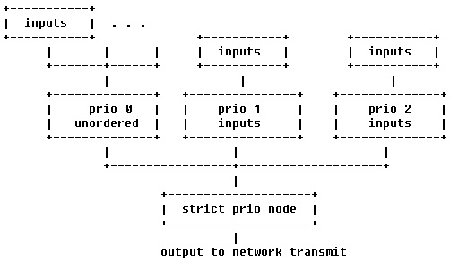
The actual qos tree configuration can be found at arch/arm/boot/dts/keystone-qostree.dtsi.
The device tree has attributes for configuring the QoS shaper. In the sections below we explain the various qos specific attributes which can be used to setup and configure a QoS shaper.
In the device tree we are setting up a shaper that is depicted below
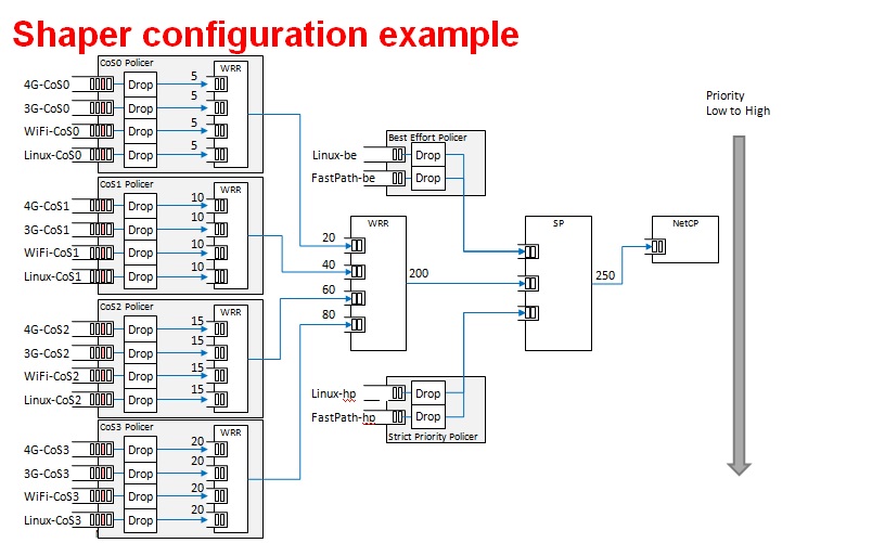
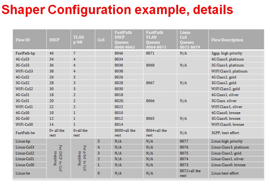
QoS Node Attributes
The following attributes are recognized within QoS configuration nodes:
- “strict-priority” and “weighted-round-robin”
e.g. strict-priority;
This attribute specifies the type of scheduling performed at a node. It is an error to specify both of these attributes in a particular node. The absence of both of these attributes defaults the node type to unordered(first come first serve).
- “weight”
e.g. weight = <80>;
This attribute specifies the weight attached to the child node of a weighted-round-robin node. It is an error to specify this attribute on a node whose parent is not a weighted-round-robin node.
- “priority”
e.g. priority = <1>;
This attribute specifies the priority attached to the child node of a strict-priority node. It is an error to specify this attribute on a node whose parent is not a strict-priority node. It is also an error for child nodes of a strict-priority node to have the same priority specified.
- “byte-units” or “packet-units”
e.g. byte-units;
The presence of this attribute indicates that the scheduler accounts for traffic in byte or packet units. If this attribute is not specified for a given node, the accounting mode is inherited from its parent node. If this attribute is not specified for the root node, the accounting mode defaults to byte units.
- “output-rate”
e.g. output-rate = <31250000 25000>;
The first element of this attribute specifies the output shaped rate in bytes/second or packets/second (depending on the accounting mode for the node). If this attribute is absent, it defaults to infinity (i.e., no shaping). The second element of this attribute specifies the maximum accumulated credits in bytes or packets (depending on the accounting mode for the node). If this attribute is absent, it defaults to infinity (i.e., accumulate as many credits as possible).
- “overhead-bytes”
e.g. overhead-bytes = <24>;
This attribute specifies a per-packet overhead (in bytes) applied in the byte accounting mode. This can be used to account for framing overhead on the wire. This attribute is inherited from parent nodes if absent. If not defined for the root node, a default value of 24 will be used. This attribute is passed through by inheritence (but ignored) on packet accounted nodes.
- “output-queue”
e.g. output-queue = <645>;
This specifies the QMSS queue on which output packets are pushed. This attribute must be defined only for the root node in the qos tree. Child nodes in the tree will ignore this attribute if specified.
- “input-queues”
e.g. input-queues = <8010 8065>;
This specifies a set of ingress queues that feed into a QoS node. This attribute must be defined only for leaf nodes in the QoS tree. Specifying input queues on non-leaf nodes is treated as an error. The absence of input queues on a leaf node is also treated as an error.
- “stats-class”
e.g. stats-class = “linux-best-effort”;
The stats-class attribute ties one or more input stage nodes to a set of traffic statistics (forwarded/discarded bytes, etc.). The system has a limited set of statistics blocks (up to 48), and an attempt to exceed this count is an error. This attribute is legal only for leaf nodes, and a stats-class attribute on an intermediate node will be treated as an error.
- “drop-policy”
e.g. drop-policy = “no-drop”
The drop-policy attribute specifies a drop policy to apply to a QoS node (tail drop, random early drop, no drop, etc.) when the traffic pattern exceeds specifies parameters. The drop-policy parameters are configured separately within device tree (see “Traffic Police Policy Attributes section below). This attribute defaults to “no drop” for applicable input stage nodes. If a node in the QoS tree specifies a drop-policy, it is an error if any of its descendent nodes (children, children of children, ...) are of weighted-round-robin or strict-priority types.
Traffic Police Policy Attributes
The following attributes are recognized within traffic drop policy nodes:
- “byte-units” or “packet-units”
e.g. byte-units;
The presence of this attribute indicates that the dropr accounts for traffic in byte or packet units. If this attribute is not specified, it defaults to byte units. Policies that use random early drop must be of byte unit type.
- “limit”
e.g. limit = <10000>;
Instantaneous queue depth limit (in bytes or packets) at which tail drop takes effect. This may be specified in combination with random early drop, which operates on average queue depth (instead of instantaneous). The absence of this attribute, or a zero value for this attribute disables tail drop behavior.
- “random-early-drop”
e.g. random-early-drop = <32768 65536 2 2000>;
The random-early-drop attribute specifies the following four parameters in order:
low threshold: No packets are dropped when the average queue depth is below this threshold (in bytes). This parameter must be specified.
high threshold: All packets are dropped when the average queue depth above this threshold (in bytes). This parameter is optional, and defaults to twice the low threshold.
max drop probability: the maximum drop probability
half-life: Specified in milli seconds. This is used to calculate the average queue depth. This parameter is optional and defaults to 2000.
Sysfs support
The keystone hardware queue driver has sysfs support for statistics, drop policies and the tree configuration.
root@k2hk-evm:~# cd /sys/devices/platform/soc/soc:qmss@2a40000/qos-inputs-0
root@k2hk-evm:/sys/devices/platform/soc/soc:qmss@2a40000/qos-inputs-0# ls
drop-policies qos-tree statistics
root@keystone-evm:/sys/devices/platform/soc/soc:qmss@2a40000/qos-inputs-0#
The above shows the location in the kernel where sysfs entries for the keystone hardware queue can be found. There are sysfs entries for the qos trees (qos-inuputs-0, qos-tree-inputs-1). Within the qos directory there are separate directories for statistics, drop-policies and the qos-tree itself. Each node in the tree is a separate directory entry, starting with the root (tip) entry.
- bytes forwarded
- bytes discarded
- packets forwarded
- packets discarded
cat /sys/devices/platform/soc/soc:qmss@2a40000/qos-inputs-0/statistics/linux-be/packets_forwarded
Drop policy configuration is also displayed for each drop policy. In the case of a drop policy, the parameters can also be changed. This is depicted below. Please note the the parameters that can be modified for tail drop are a subset of the parameters that can be modified for random early drop.
- directory entries to reach the subtrees feeding this node
- the input queues to this node (valid for leaf nodes only)
- the output queue from this node
- the output rate for the node. The current value can be shown by: “cat output_rate”. The value can be modified by: echo ”<val>” > output_rate
- the overhead bytes parameter for the node. The current value can be shown by: “cat overhead_bytes”. The value can be modified by: echo ”<val>” > overhead_bytes
- burst size . The current value can be shown by: “cat burst_size”. The value can be modified by: echo “<val>” > burst_size
- drop_policy . This is the name of the drop policy to be used.
- stats_class associated with node. This is the name of stats class to be used
- the priority of the node (for strict priority nodes only). The current value can be shown by: “cat priority”. The value can be modified by: echo “<val>” > priority
- weight : for wrr nodes. The current value can be shown by: “cat weight”. The value can be modified by: echo “<val>” > weight
Debug Filesystem support
Debug Filesystem(debugfs) support is also being provided for QoS support. To make use of debugfs support a user might have to mount a debugfs filesystem. This can be done by issuing the command (if /debug does not exist on your filesystem, you may need to create the directory first).
mount -t debugfs debugfs /debug
root@keystone-evm:/debug/qos-3# ls
config_profiles out_profiles queue_configs sched_ports
With the debugfs support we will be able to see the actual configuration of
- QoS scheduler ports
- Drop scheduler queue configs
- Drop scheduler output profiles
- Drop scheduler config profiles
root@k2hk-evm:/debug/qos-3# cat sched_ports
port 14
unit flags 15 group # 1 out q 8171 overhead bytes 24 throttle thresh 2501 cir credit 5120000 cir max 51200000
total q's 4 sp q's 0 wrr q's 4
queue 0 cong thresh 0 wrr credit 384000
queue 1 cong thresh 0 wrr credit 384000
queue 2 cong thresh 0 wrr credit 384000
queue 3 cong thresh 0 wrr credit 384000
port 15
unit flags 15 group # 1 out q 8170 overhead bytes 24 throttle thresh 2501 cir credit 5120000 cir max 51200000
total q's 4 sp q's 0 wrr q's 4
queue 0 cong thresh 0 wrr credit 384000
queue 1 cong thresh 0 wrr credit 384000
queue 2 cong thresh 0 wrr credit 384000
queue 3 cong thresh 0 wrr credit 384000
port 16
unit flags 15 group # 1 out q 8169 overhead bytes 24 throttle thresh 2501 cir credit 5120000 cir max 51200000
total q's 4 sp q's 0 wrr q's 4
queue 0 cong thresh 0 wrr credit 384000
queue 1 cong thresh 0 wrr credit 384000
queue 2 cong thresh 0 wrr credit 384000
queue 3 cong thresh 0 wrr credit 384000
port 17
unit flags 15 group # 1 out q 8168 overhead bytes 24 throttle thresh 2501 cir credit 5120000 cir max 51200000
total q's 4 sp q's 0 wrr q's 4
queue 0 cong thresh 0 wrr credit 384000
queue 1 cong thresh 0 wrr credit 384000
queue 2 cong thresh 0 wrr credit 384000
queue 3 cong thresh 0 wrr credit 384000
port 18
unit flags 15 group # 1 out q 8173 overhead bytes 24 throttle thresh 3126 cir credit 5120000 cir max 51200000
total q's 4 sp q's 0 wrr q's 4
queue 0 cong thresh 0 wrr credit 384000
queue 1 cong thresh 0 wrr credit 768000
queue 2 cong thresh 0 wrr credit 1152000
queue 3 cong thresh 0 wrr credit 1536000
port 19
unit flags 7 group # 1 out q 645 overhead bytes 24 throttle thresh 0 cir credit 6400000 cir max 51200000
total q's 3 sp q's 3 wrr q's 0
queue 0 cong thresh 0 wrr credit 0
queue 1 cong thresh 0 wrr credit 0
queue 2 cong thresh 0 wrr credit 0
root@k2hk-evm:/debug/qos-3#
Configuring QoS on an 1-GigE interface
To configure QoS on an interface, several definitions must be added to the device tree:
- Drop policies and a QoS tree must be defined. The outer-most QoS block must specify an output queue number; this may be the 1-GigE NETCP’s PA PDSP 5 (645) or CPSW (648), one of the 10-GigE CPSW’s queues (8752, 8753), or other queue as appropriate.
Example (keystone-qostree.dtsi):
droppolicies: default-drop-policies {
no-drop {
default;
packet-units;
limit = <0>;
};
...
all-drop {
byte-units;
limit = <0>;
};
};
Example (keystone-qostree.dtsi):
qostree0: qos-tree-0 {
strict-priority; /* or weighted-round-robin */
byte-units; /* packet-units or byte-units */
output-rate = <31250000 25000>;
overhead-bytes = <24>; /* valid only if units are bytes */
output-queue = <645>; /* allowed only on root node */
high-priority {
...
}
...
best-effort {
...
};
};
qostree1: qos-tree-1 {
strict-priority; /* or weighted-round-robin */
byte-units; /* packet-units or byte-units */
output-rate = <31250000 25000>;
overhead-bytes = <24>; /* valid only if units are bytes */
output-queue = <648>; /* allowed only on root node */
high-priority {
...
}
...
best-effort {
...
};
};
- QoS inputs must be defined to the hwqueue subsystem. The QoS inputs block defines which group of hwqueues will be used, and links to the set of drop policies and QoS tree to be used.
Example (k2hk-netcp.dtsi):
qmss: qmss@2a40000 {
...
queue-pools {
...
qos {
qosinputs0: qos-inputs-0 {
qrange = <8000 192>;
pdsp-id = <3>;
...
drop-policies = <&droppolicies>;
qos-tree = <&qostree0>;
reserved;
};
qosinputs1: qos-inputs-1 {
values = <6400 192>;
pdsp-id = <7>;
...
drop-policies = <&droppolicies>;
qos-tree = <&qostree2>;
reserved;
};
};
}
};
- A PDSP must be defined, and loaded with the QoS firmware.
Example (k2hk-netcp.dtsi):
qmss: qmss@2a40000 {
...
pdsps {
...
pdsp3@0x2a13000 {
firmware = "qos";
...
id = <3>;
};
pdsp7@0x2a17000 {
firmware = "qos";
...
id = <7>;
};
};
}; /* qmss */
- A NETCP QoS block must be defined. For each interface, an “interface-x” block is defined, which contains definitions for each of the QoS input subqueues to be associated with that interface.
Example (k2hk-netcp.dtsi):
netcp: netcp@2090000 {
...
qos@0 {
label = "netcp-qos";
...
interfaces {
qos0: interface-0 {
tx-queues = <645 8072 8073 8074
8075 8076 8077>;
};
qos1: interface-1 {
tx-queues = <645 6472 6473 6474
6475 6476 6477>;
};
};
};
- By default, Linux network traffic will be queued to the interface’s first subqueue. To classify and route packets from Linux to specific QoS queues, the Linux traffic control utility “tc” must be used. First a class-full root queuing discipline must be established for the interface, and then filters may be used to classify packets. These filters can use the “skbedit queue_mapping” action to set the subqueue number for the packet. Here is an example:
# Clear any existing configuration
tc qdisc del dev eth0 root
# Add DSMARK as the root qdisc
tc qdisc add dev eth0 root handle 1 dsmark indices 8 default_index 0
# Create filters to classify packets and route to queues
tc filter add dev eth0 parent 1:0 protocol ip prio 1 \
u32 match ip dport 5002 0xffff \
action skbedit queue_mapping 1
tc filter add dev eth0 parent 1:0 protocol ip prio 1 \
u32 match ip dport 5003 0xffff \
action skbedit queue_mapping 2
tc filter add dev eth0 parent 1:0 protocol ip prio 1 \
u32 match ip dport 5004 0xffff \
action skbedit queue_mapping 3
tc filter add dev eth0 parent 1:0 protocol ip prio 1 \
u32 match ip dport 5005 0xffff \
action skbedit queue_mapping 4
tc filter add dev eth0 parent 1:0 protocol ip prio 1 \
u32 match ip dport 5006 0xffff \
action skbedit queue_mapping 5
Please refer to the Linux Advanced Routing & Traffic Control how-tos and related manpages available on the Internet for more information on “tc”.
Disabling QoS on an 1-GigE interface
The released “keystone-qostree.dtsi” file contains definitions for two QoS trees which are associated with the first two ports on the 1-GigE interface in the “k2hk-netcp.dtsi” file. These default trees are configured so that traffic queued to interface subqueue 0 will bypass the QoS tree. Only traffic specifically directed to subqueues 1-6 will be processed through the hardware QoS subsystem. This may be sufficient for your needs. However, you may prefer to remove the QoS configuration entirely from the device tree.
To disable QoS on the two 1-GigE interfaces
- delete all the qos related blocks or entries shown in the examples in section Configuring QoS on an 1-GigE interface, namely
- droppolicies: default-drop-policies {...}
- qostree0: qos-tree-0 {...}
- qostree1: qos-tree-1 {...}
- qos-inputs-0 {...}
- qos-inputs-1 {...}
- pdsp3@0x2a13000 {...}
- pdsp7@0x2a17000 {...}
- qos@0 {...}
Configuring QoS on a 10-GigE interface
The following snippets together shows how to remove the QoS tree associated with the second port of the 1-GigE interface and associate it with the first port on the 10-GigE interface. In these snippets, we only depict and highlight the modifications made to the above 1-GigE examples. Contents not shown in the definitions should just be copy and paste from the file k2hk-netcp.dtsi.
Note: this is only for demonstration purpose and is not part of the release.
- Remove “netcp-qos = <&qos1>” from 1-GigE’s netcp@2090000 > netcp-interfaces > interface-1 {...}.
- Remove qos1: interface-1 { ... } from 1-GigE’s netcp qos block.
netcp: netcp@2090000 {
...
qos@0 {
label = "netcp-qos";
...
interfaces {
qos0: interface-0 {
tx-queues = <645 8072 8073 8074
8075 8076 8077>;
};
/* qos1:interface-1 removed */
};
};
- Modify the output-queue number of qostree1 to that of the transmit queue of the 10-GigE’s first port.
qostree1: qos-tree-1 {
output-queue = <8752>; /* allowed only on root node */
};
- Define a qos block in 10-GigE’s netcp@2f00000 > netcp-devices {...}.
netcpx: netcp@2f00000 {
...
netcp-devices {
...
qos@0 {
label = "netcpx-qos";
compatible = "ti,netcp-qos";
tx-channel = "xnettx";
interfaces {
qos1: interface-1 {
tx-queues = <645 6472 6473 6474
6475 6476 6477>;
};
};
};
};
};
- Finally, add a qos interface to 10-GigE’s interface-1:
netcpx: netcp@2f00000 {
...
netcp-interfaces {
...
interface-1 {
...
netcp-xqos = <&qos1>;
};
};
};
Using Accumulated queues for Network interfaces
Accumulated queues allows interrupt pacing for rx queue interrupts. Accumulated queue range is defined in DTS under the queue-pools. See keystone-<SoC>-netcp.dtsi
accumulator {
acc-low-0 {
qrange = <480 32>;
accumulator = <0 47 16 2 50>;
interrupts = <0 226 0xf01>;
multi-queue;
qalloc-by-id;
};
};
netcp: netcp@2000000 {
// other bindings
netcp-interfaces {
interface-0 {
rx-channel = "netrx0";
rx-pool = <1024 12>;
tx-pool = <1024 12>;
rx-queue-depth = <128 128 0 0>;
rx-buffer-size = <1518 4096 0 0>;
rx-queue = <8704>; <============================= replace this with 480
tx-completion-queue = <8706>;
efuse-mac = <1>;
netcp-gbe = <&gbe0>;
netcp-pa = <&pa0>;
};
interface-1 {
rx-channel = "netrx1";
rx-pool = <1024 12>;
tx-pool = <1024 12>;
rx-queue-depth = <128 128 0 0>;
rx-buffer-size = <1518 4096 0 0>;
rx-queue = <8705>;<============================= replace this with 481
tx-completion-queue = <8707>;
efuse-mac = <0>;
local-mac-address = [02 18 31 7e 3e 6f];
netcp-gbe = <&gbe1>;
netcp-pa = <&pa1>;
};
};
};
If PA is used, make sure rx-route which specifiy start queue is also replaced as shown below.
netcp: netcp@2000000 {
// other bindings
netcp-devices {
// other bindings
pa@0 {
// other bindings
rx-route = <8704 22>; <=============================== change this to <480 22>
// other bindings
};
};
};
K2HK EVM Gigabit MDC/MDIO Signal Integrity Issue
Due to a MDC/MDIO signal integrity issue in the EVM that gets showed up when a RTM Breakout Card is connected to a K2HK EVM, the Gigabit Ethernet link can go down/up repeatedly with no apparent reason except with some debug prints similar to the following shown:
[ 21.445070] netcp-1.0 2620110.netcp eth0: Link is Down
[ 22.175392] netcp-1.0 2620110.netcp eth0: Link is Up - 1Gbps/Full - flow control off
[ 24.065092] netcp-1.0 2620110.netcp eth1: Link is Down
[ 34.175092] netcp-1.0 2620110.netcp eth0: Link is Down
Software Workaround
A workaround that helps to avoid the issue is to disable the Gigabit MDIO and modify the Gigabit Ethernet interface link type to SGMII_LINK_MAC_PHY_NO_MDIO (4) by making the following changes in the default K2HK devicetree bindings.
diff --git a/arch/arm/boot/dts/keystone-k2hk-evm.dts b/arch/arm/boot/dts/keystone-k2hk-evm.dts
index ff1c0fc..0cfa003 100644
--- a/arch/arm/boot/dts/keystone-k2hk-evm.dts
+++ b/arch/arm/boot/dts/keystone-k2hk-evm.dts
@@ -200,6 +200,7 @@
};
};
+/*
&mdio {
status = "ok";
thphy0: ethernet-phy@0 {
@@ -212,6 +213,7 @@
reg = <1>;
};
};
+*/
&gbe_serdes {
status = "okay";
diff --git a/arch/arm/boot/dts/keystone-k2hk-netcp.dtsi b/arch/arm/boot/dts/keystone-k2hk-netcp.dtsi
index f51d20b..0d98f1f 100644
--- a/arch/arm/boot/dts/keystone-k2hk-netcp.dtsi
+++ b/arch/arm/boot/dts/keystone-k2hk-netcp.dtsi
@@ -370,14 +370,14 @@ netcp: netcp@2000000 {
gbe0: interface-0 {
phys = <&serdes_lane0>;
slave-port = <0>;
- link-interface = <1>;
- phy-handle = <ðphy0>;
+ link-interface = <4>;
+ /* phy-handle = <ðphy0>; */
};
gbe1: interface-1 {
phys = <&serdes_lane1>;
slave-port = <1>;
- link-interface = <1>;
- phy-handle = <ðphy1>;
+ link-interface = <4>;
+ /* phy-handle = <ðphy1>; */
};
};
Hardware Fix
As of Oct 10, 2016, it is reported that Mistral Solutions Inc. (vendor of the RTM-BOC) has produced a newer version (v2.16) of the RTM-BOC that has fixed the signal integrity issue. However the hardware fix has not yet been verified by the software development team.
10G SerDes Auto-Configuration
The 10G ethernet switch found in K2HK and K2E includes a MCU which allows running a firmware to perform SerDes configuration without the intervention of the switch driver.
Enabling Auto-Configuration
To enable 10G SerDes auto-configuration, add the following in keystone-k2hk-evm.dts or keystone-k2e-evm.dts.
+&xgbe_subsys {
+ status = "okay";
+};
+
+&xgbe_pcsr {
+ status = "okay";
+};
+
+&xgbe_serdes {
+ status = "okay";
+
+ clocks = <&clkxge>;
+ clock-names = "xge_clk";
+
+ mcu-firmware {
+ status = "okay";
+
+ lane@0 {
+ status = "okay";
+ };
+
+ lane@1 {
+ status = "okay";
+ };
+ };
+};
+
+&netcpx {
+ status = "okay";
+};
Usage Note
- After the DUT bootup is completed, notice the all the enabled 10G interfaces are up and running. Then verify the 10G interfaces as usual, such as using the ping command.
- Due to constraints there are several usage notes concerning the firmware:
- When autonegotiation occurs there is a reset asserted on the lane
that affects the MAC layer and switch.
- During a simultaneous boot of two devices they will sync and autonegotiate before the aforementioned layers are configured. There is no issue in this scenario.
- If a single device is reset this will cause autonegotiation to occur again. This will reset the lane of the device that stayed persistently on. When this happens, re-program the MAC_CONTROL register for that lane, otherwise, an interface toggle using ‘ifconfig’ is sufficient to reconfigure the interface back to a working state.
- When switching between a non-FW configuration and a FW configuration a POR is required.
- Due to errata KeyStoneII.BTS_errata_advisory.29:10GbE PCS Causes
Data Corruption, occasionally on link negotiation there may be high
levels of packet loss.
- The symptoms of this are high packet loss, CRC and alignment errors, and 0xff block errors in a small time period.
- When this case is detected, assert SerDes Signal Detect low to
reforce an autonegotiation, then follow the above procedure for an
interface toggle.
- Signal detect is located at register LANE_004, BITS[2:1]. BIT[2] is override enable and BIT[1] is the override value. Once override enable is set it will force the override value as the value of signal detect. To force signal detect low, the proper write would be BITS[2:1] = 0x2. Once this has been set the firmware will respond to the lane being down and re-do auto-negotiation, automatically clearing the signal detect low state.
- If there is a total loss of signal, restarting the firmware may help.
- The firmware can be restarted by writing to CPU_CTRL register, POR_EN bit 29. Set this bit high, then set it low with at least 10ms in between.
3.3.4.15. PRUSS
Introduction
All the Industrial Development Kit (IDK) boards can support 2 Ethernet ports per PRUSS (Programmable Real-time Unit Subsystem). Although it is meant to support real-time Industrial Ethernet protocols this wiki page will only describe how to get standard Ethernet working using the Kernel’s PRU Ethernet driver.
Acronyms & definitions
| Acronym | Definition |
|---|---|
| IDK | Industrial Development Kit |
| PRU | Programmable Real-time Unit |
Table: PRU Ethernet Driver: Acronyms
PRU Ethernet Driver Architecture
Below figure shows the PRU Ethernet Driver architecture.
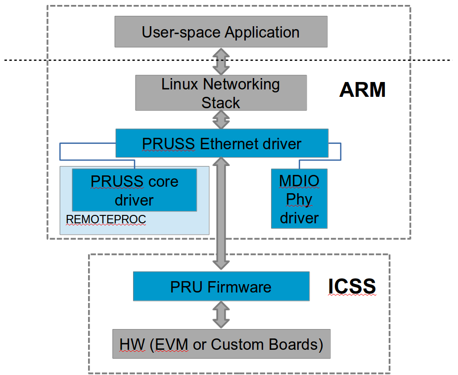
Overview
Each PRUSS instance contains 2 PRU cores and 2 Ethernet PHY interfaces. This means that each PRU core can fully own one Ethernet port allowing us to create a dual Ethernet solution. The firmware running on each PRU implements the Ethernet MAC application. It uses the System OCMC RAM to exchange network packets between firmware and PRU Ethernet kernel driver.
Before the PRU Ethernet kernel driver can start transferring packets, the following things have to be done:
- Initialize the PRU cores and load the correct formware. This is taken care by the Remoteproc core via the PRU Remoteproc driver (pru_rproc.c).
- Initialize the PRUSS Interrupt Controller (INTC) and configure the interrupt mapping as per firmware requirement. This is done by the PRUSS INTC driver (pruss_intc.c).
- Initialize the Ethernet PHYs over the MDIO interface. This is done by the PHY MDIO driver (davinci_mdio.c).
Once all initialization is done the PRU Ethernet driver (prueth.c) takes over and interfaces with the firmware using PRUSS internal RAM (DRAM & SRAM) and the System OCMC RAM. It also interfaces to the Linux Networking stack to provide the standard networking interface to user space.
Files
| S.No | Location | Description |
|---|---|---|
| 1 | drivers/net/ethernet/ti/prueth.c | PRU Ethernet driver |
| 2 | drivers/remoteproc/pruss.c | PRUSS core driver |
| 3 | drivers/remoteproc/pruss_intc.c | PRUSS INTC driver |
| 4 | drivers/remoteproc/pru_rproc.c | PRU Remoteproc driver |
| 5 | drivers/net/ethernet/ti/davinci_mdio.c | PHY MDIO driver |
| 6 | lib/firmware/ti-pruss/ | Firmware |
Board specific Setup Details
AM335x-ICE-v2
This board has only 2 Ethernet ports that can be used either as CPSW Ethernet or PRUSS Ethernet. For PRUSS Ethernet configration place jumpers J18 and J19 at MII position before powering up the board.
AM437x-IDK
This board as one Gigabit (CPSW) Ethernert port and 2 PRUSS Ethernet ports. No special board configuration is needed to use all ports.
K2G-ICE EVM
This board has one Gigabit (netCP) Ethernet port and 4 PRUSS Ethernet ports. No special board configuration is needed to use all ports.
AM571x-IDK
This board has 2 Gigabit (CPSW) Ethernet ports and 4 PRUSS Ethernet ports. Due to pinmux limitations it can support either of the following configurations
- Jumper J51 placed. LCD + 2 Gigabit (CPSW) + 2 PRUSS Ethernet ports (PRU2_ETH0 and PRU2_ETH1)
OR
- Jumper J51 removed. No LCD, 2 Gigabit (CPSW) + 4 PRUSS Ethernet ports.
NOTE: Jumper must be configured before powering up the board.
AM572x-IDK
This board has 2 Gigabit (CPSW) Ethernet ports and 4 PRUSS Ethernet ports. However, only 2 Gigabit + 2 PRUSS Ethernet ports (PRU2_ETH0 and PRU2_ETH1) are supported due to pinmux limitations.
NOTE: Only ES2.0 silicon (Board Rev1.3 or later) is supported as older Silicon uses a older version of PRUSS core that is not compatible with the supplied firmware.
Kernel configuration
To enable/disable PRU Ethernet driver support, start the Linux Kernel Configuration tool:
$ make menuconfig ARCH=arm
Make sure Remoteproc and PRUSS core driver is enabled.
Select Device drivers from the main menu.
...
[*] Networking support --->
Device Drivers -->
File systems --->
...
Select Remoteproc drivers.
...
[*] IOMMU Hardware Support --->
Remoteproc drivers --->
Rpmsg drivers --->
...
Enable the below drivers.
...
<M> Support for Remote Processor subsystem
<M> TI PRUSS remoteproc support
<M> Keystone Remoteproc support
...
Go back to the Device drivers menu Network device support.
...
IEEE 1394 (FireWire) support --->
[*] Network device support --->
[ ] Open-Channel SSD target support ----
...
Select Ethernet driver support.
...
Distributed Switch Architecture drivers ----
[*] Ethernet driver support --->
< > FDDI driver support
...
Select TI PRU Ethernet driver.
...
< > TI ThunderLAN support
<M> TI PRU Ethernet EMAC/Switch driver
[ ] VIA devices
...
Driver Usage & Testing
You can use standard Linux networking tools to test the networking interface (e.g. ifconfig, ping, iperf, scp, ethtool, etc)
3.3.4.16. PCIe End Point
Introduction
PCI controller IPs integrated in DRA7x/AM57x and 66AK2G SoCs are capable of operating either in Root Complex mode (host) or Endpoint mode (device). When operating in endpoint mode, the controller can be configured to be used as any function depending on the use case (‘Test endpoint’ is the only PCIe EP function supported in Linux kernel right now)
This wiki page provides usage information of PCIe EP Linux driver.
Setup Details
The following boards have standard female connector
| dra74x-evm |
| dra72x-evm |
| am571x-idk |
| am572x-idk |
| 66ak2g-gp-evm |
These boards are by default intended to be operated in Root Complex mode. So in order to connect two boards, a specialized cable like below is required.
This cable can be obtained from https://www.adexelec.com/pciexp.htm. Use either X1 cable or X4 cable depending on the slot provided in the board. The part number is PE-FLEX1-MM-CX-3” (for 3” cable length x1)
Modify the cable to remove resistors in CK+ and CK- in order to avoid ground loops (power) and smoking clock drivers (clk+/-).
The ends of the modified cable should look like below
B side
A side
A side side2
B side side2
Image of a dra72-evm and dra7-evm connected back to back. There is no restriction on which end of the cable should be connected to host and device.
..note:
For AM572x GP EVM, there is a Mini PCIe connector on
the LCD board. To connect 2 boards involving a AM572x GP EVM, a
mPCIe-to-PCIe adapter is needed.
EP Device
DTS Modification
The default dts is configured to be used in root complex mode. In order to use it in endpoint mode, the following changes has to be made in dts file.
To configure dra7-evm in EP mode:
diff --git a/arch/arm/boot/dts/dra7-evm.dts b/arch/arm/boot/dts/dra7-evm.dts
index eedd930..93d9f17 100644
--- a/arch/arm/boot/dts/dra7-evm.dts
+++ b/arch/arm/boot/dts/dra7-evm.dts
@@ -1084,7 +1084,7 @@
vdd-supply = <&smps7_reg>;
};
-&pcie1_rc {
+&pcie1_ep {
status = "okay";
};
To configure dra72-evm in EP mode:
diff --git a/arch/arm/boot/dts/dra72-evm-common.dtsi b/arch/arm/boot/dts/dra72-evm-common.dtsi
index f914e6a..9697ea3 100644
--- a/arch/arm/boot/dts/dra72-evm-common.dtsi
+++ b/arch/arm/boot/dts/dra72-evm-common.dtsi
@@ -708,6 +708,6 @@
watchdog-timers = <&timer10>;
};
-&pcie1_rc {
+&pcie1_ep {
status = "okay";
};
To configure am572x-idk in EP mode:
diff --git a/arch/arm/boot/dts/am572x-idk.dts b/arch/arm/boot/dts/am572x-idk.dts
index b2edeab..1ef70b3 100644
--- a/arch/arm/boot/dts/am572x-idk.dts
+++ b/arch/arm/boot/dts/am572x-idk.dts
@@ -428,11 +428,11 @@
};
&pcie1_rc {
- status = "okay";
gpios = <&gpio3 23 GPIO_ACTIVE_HIGH>;
};
&pcie1_ep {
+ status = "okay";
gpios = <&gpio3 23 GPIO_ACTIVE_HIGH>;
};
Linux Driver Configuration
The following config options has to be enabled in order to configure the PCI controller to be used as a “Endpoint Test” function driver.
CONFIG_PCI_ENDPOINT=y
CONFIG_PCI_EPF_TEST=y
CONFIG_PCI_DRA7XX_EP=y
Endpoint Controller devices and Function drivers
To find the list of endpoint controller devices in the system:
# ls /sys/class/pci_epc/
51000000.pcie_ep
To find the list of endpoint function drivers in the system:
# ls /sys/bus/pci-epf/drivers
pci_epf_test
Using the pci-epf-test function driver
The pci-epf-test function driver can be used to test the endpoint functionality of the PCI controller. Some of the tests that’s currently supported are
- BAR tests
- Interrupt tests (legacy/MSI)
- Read tests
- Write tests
- Copy tests
4.4 Kernel
creating pci-epf-test device
PCI endpoint function device can be created using the configfs. To create pci-epf-test device, the following commands can be used
# mount -t configfs none /sys/kernel/config
# cd /sys/kernel/config/pci_ep/
# mkdir pci_epf_test.0
The “mkdir pci_epf_test.0” above creates the pci-epf-test function device. The name given to the directory preceding ‘.’ should match with the name of the driver listed in ‘/sys/bus/pci-epf/drivers’ in order for the device to be bound to the driver.
The PCI endpoint framework populates the directory with configurable fields.
# cd pci_epf_test.0
# ls
baseclass_code function revid vendorid
cache_line_size interrupt_pin subclass_code
deviceid peripheral subsys_id
epc progif_code subsys_vendor_id
The driver populates these entries with default values when the device is bound to the driver. The pci-epf-test driver populates vendorid with 0xffff and interrupt_pin with 0x0001
# cat vendorid
0xffff
# cat interrupt_pin
0x0001
configuring pci-epf-test device
The user can configure the pci-epf-test device using the configfs. In order to change the vendorid and the number of MSI interrupts used by the function device, the following command can be used.
# echo 0x104c > vendorid
# echo 16 > msi_interrupts
Binding pci-epf-test device to a EP controller
In order for the endpoint function device to be useful, it has to be bound to a PCI endpoint controller driver. Use the configfs to bind the function device to one of the controller driver present in the system.
# echo "51000000.pcie_ep" > epc
Once the above step is completed, the PCI endpoint is ready to establish a link with the host.
4.9 Kernel
creating pci-epf-test device
PCI endpoint function device can be created using the configfs. To create pci-epf-test device, the following commands can be used
# mount -t configfs none /sys/kernel/config
# cd /sys/kernel/config/pci_ep/
# mkdir dev
# mkdir dev/epf/pci_epf_test.0
The “mkdir dev/epf/pci_epf_test.0” above creates the pci-epf-test function device. The name given to the directory preceding ‘.’ should match with the name of the driver listed in ‘/sys/bus/pci-epf/drivers’ in order for the device to be bound to the driver.
The PCI endpoint framework populates the directory with configurable fields.
# ls dev/epf/pci_epf_test.0/
baseclass_code function revid vendorid
cache_line_size interrupt_pin subclass_code
deviceid peripheral subsys_id
epc progif_code subsys_vendor_id
The driver populates these entries with default values when the device is bound to the driver. The pci-epf-test driver populates vendorid with 0xffff and interrupt_pin with 0x0001
# cat dev/epf/pci_epf_test.0/vendorid
0xffff
# cat dev/epf/pci_epf_test.0/interrupt_pin
0x0001
configuring pci-epf-test device
The user can configure the pci-epf-test device using the configfs. In order to change the vendorid and the number of MSI interrupts used by the function device, the following command can be used.
Configure Texas Instruments as the vendor.
# echo 0x104c > dev/epf/pci_epf_test.0/vendorid
If the endpoint is a DRA74x or AM572x device:
# echo 0xb500 > dev/epf/pci_epf_test.0/deviceid
If the endpoint is a DRA72x or AM572x device:
# echo 0xb501 > dev/epf/pci_epf_test.0/deviceid
Then finally:
# echo 16 > dev/epf/pci_epf_test.0/msi_interrupts
Binding pci-epf-test device to a EP controller
In order for the endpoint function device to be useful, it has to be bound to a PCI endpoint controller driver. Use the configfs to bind the function device to one of the controller driver present in the system.
# echo "51000000.pcie_ep" > dev/epc
Once the above step is completed, the PCI endpoint is ready to establish a link with the host.
4.14 Kernel
The following steps should be followed for the upstreamed solution (from 4.12 kernel). The custom solution used in 4.9/4.4 should not be used for upstreamed solution.
creating pci-epf-test device
PCI endpoint function device can be created using the configfs. To create pci-epf-test device, the following commands can be used
# mount -t configfs none /sys/kernel/config
# cd /sys/kernel/config/pci_ep/
# mkdir functions/pci_epf_test/func1
The “mkdir functions/pci_epf_test/func1” above creates the pci-epf-test function device.
The PCI endpoint framework populates the directory with configurable fields.
# ls functions/pci_epf_test/func1
baseclass_code function revid vendorid
cache_line_size interrupt_pin subclass_code
deviceid peripheral subsys_id
epc progif_code subsys_vendor_id
The driver populates these entries with default values when the device is bound to the driver. The pci-epf-test driver populates vendorid with 0xffff and interrupt_pin with 0x0001
# cat functions/pci_epf_test/func1/vendorid
0xffff
# cat functions/pci_epf_test/func1/interrupt_pin
0x0001
configuring pci-epf-test device
The user can configure the pci-epf-test device using the configfs. In order to change the vendorid and the number of MSI interrupts used by the function device, the following command can be used.
Configure Texas Instruments as the vendor.
# echo 0x104c > functions/pci_epf_test/func1/vendorid
If the endpoint is a DRA74x or AM572x device:
# echo 0xb500 > functions/pci_epf_test/func1/deviceid
If the endpoint is a DRA72x or AM572x device:
# echo 0xb501 > functions/pci_epf_test/func1/deviceid
Then finally:
# echo 16 > functions/pci_epf_test/func1/msi_interrupts
Binding pci-epf-test device to a EP controller
In order for the endpoint function device to be useful, it has to be bound to a PCI endpoint controller driver. Use the configfs to bind the function device to one of the controller driver present in the system.
# ln -s functions/pci_epf_test/func1 controllers/51000000.pcie_ep/
Starting the EP device
In order for the EP device to be ready to establish the link, the following command should be given
# echo 1 > controllers/51000000.pcie_ep/start
Once the above step is completed, the PCI endpoint is ready to establish a link with the host.
66AK2G Limitation
K2G outbound transfers has a limitation that the target address should be aligned to a minimum of 1MB address. This restriction is because of PCIE_OB_OFFSET_INDEXn where BITS 1 to 19 is reserved. (Please note 1MB is minimum alignment and it can be changed to 1MB/2MB/4MB/8MB by specifying it in PCIE_OB_SIZE register).
Outbound transfers are used by PCI endpoint to access RC’s memory and for raising MSI interrupts. So with 1MB restriction both RC memory and MSI interrupts will be impacted since standard linux API’s like dma_alloc_coherent, get_free_pages etc.. doesn’t give 1MB aligned memory. While custom driver can be created to get 1MB aligned memory for accessing RC’s memory, MSI memory is allocated by RC controller driver and there is no way to tell it to give 1MB aligned address.
These restrictions are not specified in PCI standard and is bound to cause issues for 66AK2G users.
HOST Device
The PCI EP device must be powered-on and configured before the PCI HOST device. This restriction is because the PCI HOST doesn’t have hot plug support.
Linux Driver Configuration
The following config options has to be enabled in order to use the “Endpoint Test” PCI device.
CONFIG_PCI=y
CONFIG_PCI_ENDPOINT_TEST=y
CONFIG_PCI_DRA7XX_HOST=y
lspci output
00:00.0 PCI bridge: Texas Instruments Device 8888 (rev 01)
01:00.0 Unassigned class [ff00]: Texas Instruments Device b500
Using the Endpoint Test function device
pci_endpoint_test driver creates the Endpoint Test function device (/dev/pci-endpoint-test.0) which will be used by the following pcitest utility. pci_endpoint_test can either be built-in to the kernel or built as a module. For testing legacy interrupt, MSI interrupt has to disabled in the host.
In order to not enable MSI (for testing legacy interrupt in DRA7)
insmod pci_endpoint_test.ko no_msi=1
Please note MSI interrupt by default is not enabled for K2G.
pcitest.sh added in tools/pci/ can be used to run all the default PCI endpoint tests. Before pcitest.sh can be used pcitest.c should be compiled using
cd <kernel-dir>
make headers_install ARCH=arm
arm-linux-gnueabihf-gcc -Iusr/include tools/pci/pcitest.c -o pcitest
cp pcitest <rootfs>/usr/sbin/
cp tools/pci/pcitest.sh <rootfs>
pcitest.sh output
root@dra7xx-evm:~# ./pcitest.sh
BAR tests
BAR0: OKAY
BAR1: OKAY
BAR2: OKAY
BAR3: OKAY
BAR4: NOT OKAY
BAR5: NOT OKAY
Interrupt tests
LEGACY IRQ: NOT OKAY
MSI1: OKAY
MSI2: OKAY
MSI3: OKAY
MSI4: OKAY
MSI5: OKAY
MSI6: OKAY
MSI7: OKAY
MSI8: OKAY
MSI9: OKAY
MSI10: OKAY
MSI11: OKAY
MSI12: OKAY
MSI13: OKAY
MSI14: OKAY
MSI15: OKAY
MSI16: OKAY
MSI17: NOT OKAY
MSI18: NOT OKAY
MSI19: NOT OKAY
MSI20: NOT OKAY
MSI21: NOT OKAY
MSI22: NOT OKAY
MSI23: NOT OKAY
MSI24: NOT OKAY
MSI25: NOT OKAY
MSI26: NOT OKAY
MSI27: NOT OKAY
MSI28: NOT OKAY
MSI29: NOT OKAY
MSI30: NOT OKAY
MSI31: NOT OKAY
MSI32: NOT OKAY
Read Tests
READ ( 1 bytes): OKAY
READ ( 1024 bytes): OKAY
READ ( 1025 bytes): OKAY
READ (1024000 bytes): OKAY
READ (1024001 bytes): OKAY
Write Tests
WRITE ( 1 bytes): OKAY
WRITE ( 1024 bytes): OKAY
WRITE ( 1025 bytes): OKAY
WRITE (1024000 bytes): OKAY
WRITE (1024001 bytes): OKAY
Copy Tests
COPY ( 1 bytes): OKAY
COPY ( 1024 bytes): OKAY
COPY ( 1025 bytes): OKAY
COPY (1024000 bytes): OKAY
COPY (1024001 bytes): OKAY
Files
S.No Location Description 1 drivers/pci/endpoint/pci-epc-core.c drivers/pci/endpoint/pci-ep-cfs.c
drivers/pci/endpoint/pci-epc-mem.c
drivers/pci/endpoint/pci-epf-core.c
PCI Endpoint Framework 2 drivers/pci/endpoint/functions/pci-epf-test.c PCI Endpoint Function Driver 3 drivers/misc/pci_endpoint_test.c PCI Driver 4 tools/pci/pcitest.c tools/pci/pcitest.sh
PCI Userspace Tools 5 *4.4 Kernel* drivers/pci/controller/pci-dra7xx.c
drivers/pci/controller/pcie-designware.c
drivers/pci/controller/pcie-designware-ep.c
drivers/pci/controller/pcie-designware-host.c
*4.9 Kernel*
drivers/pci/dwc/pci-dra7xx.c
drivers/pci/dwc/pcie-designware.c
drivers/pci/dwc/pcie-designware-ep.c
drivers/pci/dwc/pcie-designware-host.c
PCI Controller Driver
3.3.4.17. PCIe Root Complex
PCIe driver
The PCI Express (PCIe) module is a multi-lane I/O interconnect providing low pin count, high reliability, and high-speed data transfer at rates of up to 5.0 Gbps per lane per direction, for serial links on backplanes and printed wiring boards. It is a 3rd Generation I/O Interconnect technology succeeding ISA and PCI bus that is designed to be used as a general-purpose serial I/O interconnect in multiple market segments, including desktop, mobile, server, storage and embedded communications.
Keystone PCIe
Keystone PCIe module is used on K2H/K2K, K2E, K2L and K2G SoCs. For more details on the module specification, please refers to sprugs6d.pdf documentation provided at ti.com. The K2G PCIe module spec is part of spruhy8d.pdf.
Supported platforms
SoCs: K2E, K2G
Keystone PCIe driver may be used on K2L/K2HK and boards/EVMs using these SoCs, but is not validated since nothing is hooked to PCIe port on these EVMs.
K2E EVM has a Marvel SATA controller (88se9182) hooked to PCIe port 1. The Driver is validated by connecting a SATA hard disk to the SATA port available on the EVM. K2G EVM has a single x1 PCIe slot which accepts standard PCIe cards. Following PCIe cards are validated for basic functionality on K2G EVM:-
* Ethernet: Broadcom Corporation NetXtreme BCM5721 Gigabit (tg3 driver)
* Intel Corporation 82572EI Gigabit Ethernet (e1000e driver)
* USB: Texas Instruments TUSB73x0 SuperSpeed USB 3.0 xHCI Host
* SATA: Marvell Technology Group Ltd. 88SE9120 SATA 6Gb/s
K2G EVM: Make sure following jumper settings on the EVM:-
* J44: put stub to short pin 1 & 2. This ensure proper reset to PCIe slot
* J15: put stub to short pin 2 & 3. This ensures 100MHz clock to PCIe slot
Introduction
The TI Keystone platforms contain a PCI Express module which supports a multi-lane I/O interconnect providing low pin count, high reliability, and high-speed data transfer at rates of up to 5.0 Gbps per lane per direction, The module supports Root Complex and End Point operation modes.
The PCIe driver implemented supports only the Root Complex (RC) operation mode on K2 platforms (K2HK, K2E). The PCIe driver is designed based on PCIE Designware Core driver. The Designware Core driver is enhanced to support Keystone PCIe driver in the mainline kernel. The diagram below shows the various drivers that Keystone PCI depends on to implement the RC driver. PCI Designware Core driver provides a set of function calls defined in drivers/pci/host/pcie-designware.h for platform drivers to implement the RC driver. Keystone PCI module required some enhancements to designware core because of the application register space which otherwise is part of the designware core. These keystone specific handling of the driver is re-factored into PCI Keystone DW Core Driver and used from PCI Keystone platform driver. This includes MSI/Legacy IRQ handling, Read/Write functions to write over the PCI bus etc which are unique for Keystone PCI driver.
Callbacks
|------------------| |--------------------| |---------------------| |---------------|
| PCI Keystone |<------| PCI Keystone DW |<------| PCI Designware Core | | |
| Platform Driver |------>| Core Driver |------>| Driver |-------| PCI Core |
| (pci-keystone.c) | | pci-keystone-dw.c | | pcie-designware.c | | |
|------------------| |--------------------| |---------------------| |---------------|
function calls function calls
----------- SATA 6Gbps data cable ------------
| WD10EZEX | --------------------------> | K2E EVM |
----------- ------------
^
|
(External power supply)
Connect HDD to an external power supply. Connect the HDD SATA port to K2E EVM SATA port using a 6Gbps data cable and power on the HDD. Power On K2E EVM. The K2E rev 1.0.2.0 requires a hardware modification to get the SATA detection on the PCI bus. Please check with EVM hardware vendor for the details.
For K2G EVM, there is a PCIe slot available to work with standard PCIe cards. For example to test PCIe SATA as in K2E, connect the hard disk SATA cables to the PCIe SATA controller card and insert the card into the PCIe slot and Power on the EVM. Other PCIe cards can be tested in a similar way.
Driver Configuration
Assume, you have default configuration set for kernel build. To enable PCI Keystone driver, traverse the following config tree from menuconfig
Bus support --->
[*] PCI support
[*] Message Signaled Interrupts (MSI and MSI-X)
[ ] PCI Debugging
[ ] Enable PCI resource re-allocation detection
......
PCI host controller drivers --->
[ ] Generic PCI host controller
[*] TI Keystone PCIe controller
The RC driver can be built into the kernel as a static module.
Device Tree bindings
DT documentation is at Documentation/devicetree/bindings/pci/pci-keystone.txt in the kernel source tree. The PCIE SerDes Phy related DT documentation is available at Documentation/devicetree/bindings/phy/ti-phy.txt
Driver Source location
The driver code is located at drivers/pci/host
Files: pci-keystone.c
pci-keystone-dw.c
pci-keystone.h
PCI driver calls into Phy SerDes driver to initialize PCI Phy (SerDes). From PCI probe function, phy_init() is called which results in SerDes initialization. The SerDes code is a common driver used across all sub systems such as SGMII, PCIe and 10G. The driver code for this located at drivers/phy/phy-keystone-serdes.c
Limitations
- PCIe is verified only on K2E and K2G EVMs
- AER error interrupt is not handled by PCIE AER driver for Keystone as this uses non standard platform interrupt
- ASPM interrupt is non standard on Keystone and the same is not handled by the PCIe ASPM driver.
U-Boot environment/scripts
The Keystone PCIe SerDes Phy hardware requires a firmware to configure the Phy to work as a PCIe phy. As Keystone PCIe is statically built into the kernel, this firmware is needed when Phy SerDes driver is probed. When initramfs is used as the final rootfs, this firmware can reside at /lib/firmware folder of the fs. For other boot modes (mmc, ubi, nfs), k2-fw-initrd.cpio.gz has this firmware and can be loaded to memory and the address is passed to kernel through second argument of bootm command. Following env scripts are used to customize the u-boot environment for various boot modes so that firmware is available to initialize the phy SerDes when Phy SerDes driver is probed.
firmware file ks2_pcie_serdes.bin is available in ti-linux-firmware.git at ti-keystone folder or at /lib/firmware folder of the file system images shipped with the release or under /lib/firmare folder of the k2-fw-initrd.cpio.gz shipped with the release). If you are using your own file system, make sure ks2_pcie_serdes.bin resides at /lib/firmware folder.
Setup u-boot env as follows. These are expected to be available in the default env variable, but check and update it if not present.
setenv init_fw_rd_mmc 'load mmc ${bootpart} ${rdaddr} ${bootdir}/${name_fw_rd}; run set_rd_spec'
setenv init_fw_rd_net 'dhcp ${rdaddr} ${tftp_root}/${name_fw_rd}; run set_rd_spec'
setenv init_fw_rd_ramfs 'setenv rd_spec - '
setenv init_fw_rd_ubi 'ubifsload ${rdaddr} ${bootdir}/${name_fw_rd}; run set_rd_spec'
setenv set_rd_spec 'setenv rd_spec ${rdaddr}:${filesize}'
setenv name_fw_rd 'k2-fw-initrd.cpio.gz'
Add init_fw_rd_${boot} to bootcmd.
setenv bootcmd 'run envboot; run set_name_pmmc init_${boot} init_fw_rd_${boot} get_pmmc_${boot} run_pmmc get_fdt_${boot} get_mon_${boot} get_kern_${boot} run_mon run_kern'
Procedure to boot Linux with FS on hard disk
Enable AHCI, ATA drivers
Assume, you have default configuration set for kernel build. Both AHCI and ATA drivers are to be enabled to build statically into the kernel image if rootfs is mounted from the hard disk. Otherwise, if hard disk is used as a storage device, the below drivers can be built as dynamic modules and loaded from user space.
From Kernel menuconfig, traverse the configuration tree as follows:-
Device Drivers --->
---------
< > ATA/ATAPI/MFM/RLL support (DEPRECATED) ----
SCSI device support --->
<*> Serial ATA and Parallel ATA drivers (libata) --->
*** Controllers with non-SFF native interface ***
<*> AHCI SATA support
<*> Platform AHCI SATA support
< > CEVA AHCI SATA support
-----------------
*** Generic fallback / legacy drivers ***
<*> Generic ATA support
< > Legacy ISA PATA support (Experimental)
[ ] Multiple devices driver support (RAID and LVM) ----
Boot Linux kernel on K2E EVM using NFS file system or Ramfs and using rootfs provided in the SDK. Make sure SATA HDD is connected to EVM as explained above and SATA EP is detected during boot up. This example uses a 1TB HDD and create two partition. First partition is for filesystem and is 510GB and second is for swap and is 256MB.
Create partition with fdisk
First step is to create 2 partitions using fdisk command. At Linux console type the following commands
root@keystone-evm:~# fdisk /dev/sda
Welcome to fdisk (util-linux 2.21.2).
Changes will remain in memory only, until you decide to write them.
Be careful before using the write command.
Device does not contain a recognized partition table
Building a new DOS disklabel with disk identifier 0x9b51b66e.
The device presents a logical sector size that is smaller than
the physical sector size. Aligning to a physical sector (or optimal
I/O) size boundary is recommended, or performance may be impacted.
Command (m for help): m
Command action
a toggle a bootable flag
b edit bsd disklabel
c toggle the dos compatibility flag
d delete a partition
l list known partition types
m print this menu
n add a new partition
o create a new empty DOS partition table
p print the partition table
q quit without saving changes
s create a new empty Sun disklabel
t change a partition's system id
u change display/entry units
v verify the partition table
w write table to disk and exit
x extra functionality (experts only)
Command (m for help): n
Partition type:
p primary (0 primary, 0 extended, 4 free)
e extended
Select (default p): p
Partition number (1-4, default 1): 1
First sector (2048-1953525167, default 2048): 2048
Last sector, +sectors or +size{K,M,G} (2048-1953525167, default 1953525167): +510G
Partition 1 of type Linux and of size 510 GiB is set
Command (m for help): n
Partition type:
p primary (1 primary, 0 extended, 3 free)
e extended
Select (default p): p
Partition number (1-4, default 2): 2
First sector (1069549568-1953525167, default 1069549568):
Using default value 1069549568
Last sector, +sectors or +size{K,M,G} (1069549568-1953525167, default 1953525167): +256M
Partition 2 of type Linux and of size 256 MiB is set
Command (m for help): p
Disk /dev/sda: 1000.2 GB, 1000204886016 bytes
255 heads, 63 sectors/track, 121601 cylinders, total 1953525168 sectors
Units = sectors of 1 * 512 = 512 bytes
Sector size (logical/physical): 512 bytes / 4096 bytes
I/O size (minimum/optimal): 4096 bytes / 4096 bytes
Disk identifier: 0x9b51b66e
Device Boot Start End Blocks Id System
/dev/sda1 2048 1069549567 534773760 83 Linux
/dev/sda2 1069549568 1070073855 262144 83 Linux
Command (m for help): t
Partition number (1-4): 2
Hex code (type L to list codes): L
0 Empty 24 NEC DOS 81 Minix / old Lin bf Solaris
1 FAT12 27 Hidden NTFS Win 82 Linux swap / So c1 DRDOS/sec (FAT-
2 XENIX root 39 Plan 9 83 Linux c4 DRDOS/sec (FAT-
3 XENIX usr 3c PartitionMagic 84 OS/2 hidden C: c6 DRDOS/sec (FAT-
4 FAT16 <32M 40 Venix 80286 85 Linux extended c7 Syrinx
5 Extended 41 PPC PReP Boot 86 NTFS volume set da Non-FS data
6 FAT16 42 SFS 87 NTFS volume set db CP/M / CTOS / .
7 HPFS/NTFS/exFAT 4d QNX4.x 88 Linux plaintext de Dell Utility
8 AIX 4e QNX4.x 2nd part 8e Linux LVM df BootIt
9 AIX bootable 4f QNX4.x 3rd part 93 Amoeba e1 DOS access
a OS/2 Boot Manag 50 OnTrack DM 94 Amoeba BBT e3 DOS R/O
b W95 FAT32 51 OnTrack DM6 Aux 9f BSD/OS e4 SpeedStor
c W95 FAT32 (LBA) 52 CP/M a0 IBM Thinkpad hi eb BeOS fs
e W95 FAT16 (LBA) 53 OnTrack DM6 Aux a5 FreeBSD ee GPT
f W95 Ext'd (LBA) 54 OnTrackDM6 a6 OpenBSD ef EFI (FAT-12/16/
10 OPUS 55 EZ-Drive a7 NeXTSTEP f0 Linux/PA-RISC b
11 Hidden FAT12 56 Golden Bow a8 Darwin UFS f1 SpeedStor
12 Compaq diagnost 5c Priam Edisk a9 NetBSD f4 SpeedStor
14 Hidden FAT16 <3 61 SpeedStor ab Darwin boot f2 DOS secondary
16 Hidden FAT16 63 GNU HURD or Sys af HFS / HFS+ fb VMware VMFS
17 Hidden HPFS/NTF 64 Novell Netware b7 BSDI fs fc VMware VMKCORE
18 AST SmartSleep 65 Novell Netware b8 BSDI swap fd Linux raid auto
1b Hidden W95 FAT3 70 DiskSecure Mult bb Boot Wizard hid fe LANstep
1c Hidden W95 FAT3 75 PC/IX be Solaris boot ff BBT
1e Hidden W95 FAT1 80 Old Minix
Hex code (type L to list codes): 82
Changed system type of partition 2 to 82 (Linux swap / Solaris)
Command (m for help): p
Disk /dev/sda: 1000.2 GB, 1000204886016 bytes
255 heads, 63 sectors/track, 121601 cylinders, total 1953525168 sectors
Units = sectors of 1 * 512 = 512 bytes
Sector size (logical/physical): 512 bytes / 4096 bytes
I/O size (minimum/optimal): 4096 bytes / 4096 bytes
Disk identifier: 0x9b51b66e
Device Boot Start End Blocks Id System
/dev/sda1 2048 1069549567 534773760 83 Linux
/dev/sda2 1069549568 1070073855 262144 82 Linux swap / Solaris
Format partitions
root@k2e-evm~# mkfs.ext4 /dev/sda1
mke2fs 1.42.1 (17-Feb-2012)
Filesystem label=
OS type: Linux
Block size=4096 (log=2)
Fragment size=4096 (log=2)
Stride=0 blocks, Stripe width=0 blocks
33423360 inodes, 133693440 blocks
6684672 blocks (5.00%) reserved for the super user
First data block=0
Maximum filesystem blocks=0
4080 block groups
32768 blocks per group, 32768 fragments per group
8192 inodes per group
Superblock backups stored on blocks:
32768, 98304, 163840, 229376, 294912, 819200, 884736, 1605632, 2654208,
4096000, 7962624, 11239424, 20480000, 23887872, 71663616, 78675968,
102400000
Allocating group tables: done
Writing inode tables: done
Creating journal (32768 blocks): done
Writing superblocks and filesystem accounting information: done
root@k2e-evm:~# ls -ltr /dev/sda*
brw-rw---- 1 root disk 8, 2 Sep 21 14:37 /dev/sda2
brw-rw---- 1 root disk 8, 0 Sep 21 14:37 /dev/sda
brw-rw---- 1 root disk 8, 1 Sep 21 14:40 /dev/sda1
Copy filesystem to rootfs
This procedure assumes the cpio file for SDK filesystem is available on the NFS or ramfs.
>mkdir /mnt/test
>mount -t ext4 /dev/sda1 /mnt/test
>cd /mnt/test
>cpio -i -v </<rootfs>.cpio
>cd /
>umount /mnt/test
Where rootfs.cpio is the cpio file for the SDK fileystem.
Booting with FS on harddisk
Once the harddisk is formatted and has a rootfs installed, following procedure can be used to boot Linux kernel using this rootfs.
Boot EVM to u-boot prompt. Add following env variables to u-boot environment :-
K2E EVM # setenv boot hdd
K2E EVM # setenv get_fdt_hdd 'dhcp ${fdtaddr} ${tftp_root}/${name_fdt}'
K2E EVM # setenv init_fw_rd_hdd 'dhcp ${rdaddr} ${tftp_root}/${name_fw_rd}; run set_rd_spec'
K2E EVM # setenv get_kern_hdd 'dhcp ${loadaddr} ${tftp_root}/${name_kern}'
K2E EVM # setenv get_mon_hdd 'dhcp ${addr_mon} ${tftp_root}/${name_mon}'
K2E EVM # setenv init_hdd 'run args_all args_hdd'
K2E EVM # setenv args_hdd 'setenv bootargs ${bootargs} rw root=/dev/sda1'
K2E EVM # saveenv
Now type boot command and boot to Linux. The above steps can be skipped once u-boot implements these env variables by default which is expected to be supported in the future.
3.3.4.18. Power Management
Power Management Introduction
Power management is a wide reaching topic and reducing the power a system uses is handled by a number of drivers and techniques. Power Management can broadly be classified into two categories: Dynamic/Active Power management and Idle Power Management. This page covers power topics for the v4.4 Linux kernel. This the most recent version. A full history of this guide can be found at Linux Core Power Management User’s Guide History.
Dynamic Power Management Techniques
Dynamic or active Power management techniques reduce the active power consumption by an SoC when the system is active and performing tasks.
- DVFS
- CPUIdle
- Smartreflex
Dynamic Voltage and Frequency Scaling(MPU aka CPUFREQ)
Dynamic voltage and frequency scaling, or DVFS as it is commonly known, is the ability of a part to modify both the voltage and frequency it operates at based on need, user preference, or other factors. MPU DVFS is supported in the kernel by the cpufreq driver. All supported SoCs use the generic cpufreq-cpu0 driver.
Design: OPP is a pair of voltage frequency value. When scaling from High OPP to Low OPP Frequency is reduced first and then the voltage. When scaling from a lower OPP to Higher OPP we scale the voltage first and then the frequency.
Release applicable
Latest release this documentation applies to is Kernel v4.4
Supported Devices
- DRA7xx
- J6
- AM57x
- AM437x
- AM335x
Driver Features
Dynamic voltage and frequency scaling, or DVFS as it is commonly known, is the ability of a part to modify both the voltage and frequency it operates at based on need, user preference, or other factors. MPU DVFS is supported in the kernel by the cpufreq driver. All supported SoCs use the generic cpufreq-cpu0 driver. The frequency at which the MPU operates is selected by a driver called a governor. Each governor has a different strategy for selecting the most appropriate frequency. The following governors are available within the kernel:
- ondemand: This governor samples the load of the cpu and scales it up aggressively in order to provide the proper amount of processing power.
- conservative: This governor is similar to ondemand but uses a less aggressive method of increasing the the OPP of the MPU.
- performance: This governor statically sets the OPP of the MPU to the highest possible frequency.
- powersave: This governor statically sets the OPP of the MPU to the lowest possible frequency.
- userspace: This governor allows the user to set the desired OPP using any value found within scaling_available_frequencies by echoing it into scaling_setspeed.
More in depth documentation about each governor can be found in the linux kernel documentation here: https://www.kernel.org/doc/Documentation/cpu-freq/governors.txt
By default, cpufreq, the cpufreq-cpu0 driver, and all of the standard governors are enabled with the ondemand governor selected as the default governor. To make changes, follow the instructions below.
Source Location
drivers/cpufreq/ti-cpufreq.c drivers/cpufreq/cpufreq-dt.c
TI cpufreq driver uses efuse information to scale the OPP data based on silicon characteristics. The OPP data itself is used by the cpufreq DT driver to scale voltages based on frequency changes for the CPU.
Kernel Configuration Options
The driver can be built into the kernel as a static module, dynamic module, or both.
$ make menuconfig
Select CPU Power Management from the main menu.
...
...
Boot options --->
CPU Power Management --->
Floating point emulation --->
...
Select CPU Frequency Scaling as shown here:
...
...
CPU Frequency Scaling --->
[*] CPU idle PM support
...
All relevant options are listed below:
[*] CPU Frequency scaling
<*> CPU frequency translation statistics
[*] CPU frequency translation statistics details
Default CPUFreq governor (userspace) --->
<*> 'performance' governor
<*> 'powersave' governor
-*- 'userspace' governor for userspace frequency scaling
<*> 'ondemand' cpufreq policy governor
<*> 'conservative' cpufreq governor
*** CPU frequency scaling drivers ***
<M> Generic DT based cpufreq driver
<M> Generic DT based cpufreq driver using clk notifiers
<*> Texas Instruments CPUFreq support
...
DT Configuration
The clock information and the operating-points table need to be added as given in the example below. The voltage source needs to be hooked to the cpu0 node. As given below cpu0-supply needs to be mapped to the right regulator node by looking at the schematics.
/* From arch/arm/boot/dts/am4372.dtsi */
cpus {
#address-cells = <1>;
#size-cells = <0>;
cpu: cpu@0 {
compatible = "arm,cortex-a9";
enable-method = "ti,am4372";
device_type = "cpu";
reg = <0>;
clocks = <&dpll_mpu_ck>;
clock-names = "cpu";
operating-points-v2 = <&cpu0_opp_table>;
ti,syscon-efuse = <&scm_conf 0x610 0x3f 0>;
ti,syscon-rev = <&scm_conf 0x600>;
clock-latency = <300000>; /* From omap-cpufreq driver */
};
};
/* From arch/arm/boot/dts/am437x-gp-evm.dts */
&cpu {
cpu0-supply = <&dcdc2>;
};
The operating-points table has been introduced instead of
arch/arm/mach-omap2/oppXXXX_data.c files for each platform that define
OPPs for each silicon revision. More information can be found in the
Operating Points section.
Driver Usage
All of the standard governors are built-in to the kernel, and by default the ondemand governor is selected.
To view available governors,
$ cat /sys/devices/system/cpu/cpu0/cpufreq/scaling_available_governors
conservative userspace powersave ondemand performance
To view current governor,
$ cat /sys/devices/system/cpu/cpu0/cpufreq/scaling_governor
ondemand
To set a governor,
$ echo userspace > /sys/devices/system/cpu/cpu0/cpufreq/scaling_governor
To view current OPP (frequency in kHz)
$ cat /sys/devices/system/cpu/cpu0/cpufreq/scaling_cur_freq
720000
To view supported OPP’s (frequency in kHz),
$ cat /sys/devices/system/cpu/cpu0/cpufreq/scaling_available_frequencies
275000 500000 600000 720000
To change OPP (can be done only for userspace governor. If governors like ondemand is used, OPP change happens automatically based on the system load)
$ echo 275000 > /sys/devices/system/cpu/cpu0/cpufreq/scaling_setspeed
Operating Points
The OPP platform data defined in arch/arm/mach-omap2/oppXXXX_data.c has been replaced by the TI cpufreq driver OPP modification code and the OPP tables in the DT files. These files allow defining of a different set of OPPs for each different SoC, and also selective, automatic enabling based on what is detected to be supported by the specific SoC in use.
/* From arch/arm/boot/dts/am4372.dtsi */
cpu0_opp_table: opp_table0 {
compatible = "operating-points-v2";
opp50@300000000 {
opp-hz = /bits/ 64 <300000000>;
opp-microvolt = <950000 931000 969000>;
opp-supported-hw = <0xFF 0x01>;
opp-suspend;
};
opp100@600000000 {
opp-hz = /bits/ 64 <600000000>;
opp-microvolt = <1100000 1078000 1122000>;
opp-supported-hw = <0xFF 0x04>;
};
opp120@720000000 {
opp-hz = /bits/ 64 <720000000>;
opp-microvolt = <1200000 1176000 1224000>;
opp-supported-hw = <0xFF 0x08>;
};
oppturbo@800000000 {
opp-hz = /bits/ 64 <800000000>;
opp-microvolt = <1260000 1234800 1285200>;
opp-supported-hw = <0xFF 0x10>;
};
oppnitro@1000000000 {
opp-hz = /bits/ 64 <1000000000>;
opp-microvolt = <1325000 1298500 1351500>;
opp-supported-hw = <0xFF 0x20>;
};
};
To implement Dynamic Frequency Scaling (DFS), the voltages in the table can be changed to the same fixed value to avoid any voltage scaling from taking place if the system has been designed to use a single voltage.
CPUIdle
The cpuidle framework consists of two key components:
A governor that decides the target C-state of the system. A driver that implements the functions to transition to target C-state. The idle loop is executed when the Linux scheduler has no thread to run. When the idle loop is executed, current ‘governor’ is called to decide the target C-state. Governor decides whether to continue in current state/ transition to a different state. Current ‘driver’ is called to transition to the selected state.
Release applicable
Latest release this documentation applies to is Kernel v4.4
Supported Devices
- AM335x
- AM437x
Driver Features
AM335x supports two different C-states
- MPU WFI
- MPU WFI + Clockdomain gating
AM437x supports two different C-states
- MPU WFI
- MPU WFI + Clockdomain gating
Source Location
arch/arm/mach-omap2/pm33xx-core.c
drivers/soc/ti/pm33xx.c
drivers/cpuidle/cpuidle-arm.c
Kernel Configuration Options
The driver can be built into the kernel as a static module.
$ make menuconfig
Select CPU Power Management from the main menu.
...
...
Boot options --->
CPU Power Management --->
Floating point emulation --->
...
Select CPU Idle as shown here:
...
...
CPU Frequency Scaling --->
CPU Idle --->
...
All relevant options are listed below:
[*] CPU idle PM support
[ ] Support multiple cpuidle drivers
[*] Ladder governor (for periodic timer tick)
-*- Menu governor (for tickless system)
ARM CPU Idle Drivers ----
DT Configuration
cpus {
cpu: cpu0 {
compatible = "arm,cortex-a9";
enable-method = "ti,am4372";
device-type = "cpu";
reg = <0>;
cpu-idle-states = <&mpu_gate>;
};
idle-states {
compatible = "arm,idle-state";
entry-latency-us = <40>;
exit-latency-us = <100>;
min-residency-us = <300>;
local-timer-stop;
};
};
Driver Usage
CPUIdle requires no intervention by the user for it to work, it just works transparently in the background. By default the ladder governor is selected.
It is possible to get statistics about the different C-states during runtime, such as how long each state is occupied.
# ls -l /sys/devices/system/cpu/cpu0/cpuidle/state0/
-r--r--r-- 1 root root 4096 Jan 1 00:02 desc
-r--r--r-- 1 root root 4096 Jan 1 00:02 latency
-r--r--r-- 1 root root 4096 Jan 1 00:02 name
-r--r--r-- 1 root root 4096 Jan 1 00:02 power
-r--r--r-- 1 root root 4096 Jan 1 00:02 time
-r--r--r-- 1 root root 4096 Jan 1 00:02 usage
# ls -l /sys/devices/system/cpu/cpu0/cpuidle/state1/
-r--r--r-- 1 root root 4096 Jan 1 00:05 desc
-r--r--r-- 1 root root 4096 Jan 1 00:05 latency
-r--r--r-- 1 root root 4096 Jan 1 00:03 name
-r--r--r-- 1 root root 4096 Jan 1 00:05 power
-r--r--r-- 1 root root 4096 Jan 1 00:05 time
-r--r--r-- 1 root root 4096 Jan 1 00:02 usage
Smartreflex
Adaptive Voltage Scaling(AVS) is an active PM Technique and is based on the silicon type. SmartReflex is currently only supported on DRA7 and AM57 platforms, so more detail can be found under the section specific to those SoCs here: DRA7 and AM57 SmartReflex.
Source Location
drivers/cpufreq/ti-cpufreq.c
Idle Power Management Techniques
This ensures the system is drawing minimum power when in idle state i.e no use-case is running. This is accomplished by turning off as many peripherals as that are not in use.
Suspend/Resume Support
The user can deliberately force the system to low power state. There are various levels: Suspend to memory(RAM), Suspend to disk, etc. Certains parts support different levels of idle, such as DeepSleep0 or standby, which allow additional wake-up sources to be used with less wake latency at the expense of less power savings.
Release applicable
Latest release this documentation applies to is Kernel v4.4.
Supported Devices
- DRA7xx
- J6
- AM57x
- AM437x
- AM335x
Driver Features
This is dependent on which device is in use. More information can be found in the device specific usage sections below.
Source Location
The files that provide suspend/resume differ from part to part however they generally reside in arch/arm/mach-omap2/pm****.c for the higher-level code and arch/arm/mach-omap2/sleep****.S for the lower-level code.
Kernel Configuration Options
Suspend/resume can be enable or disabled within the kernel using the same method for all parts. To configure suspend/resume, enter the kernel configuration tool using:
$ make menuconfig
Select Power management options from the main menu.
...
...
Kernel Features --->
Boot options --->
CPU Power Management --->
Floating point emulation --->
Userspace binary formats --->
Power management options --->
[*] Networking support --->
Device Drivers --->
...
...
Select Suspend to RAM and standby to toggle the power management support.
[*] Suspend to RAM and standby
-*- Run-time PM core functionality
...
< > Advanced Power Management Emulation
And then build the kernel as usual.
Power Management Usage
Although the techniques and concepts involved with power management are common across many platforms, the actual implementation and usage of each differ from part to part. The following sections cover the specifics of using the aforementioned power management techniques for each part that is supported by this release.
Common Power Management
IO Pad Configuration
In order to optimize power on the I/O supply rails, each pin can be given a “sleep” configuration in addition to it’s run-time configuration. This can be handled with the pinctrl states defined in the board device tree for each peripheral. These values are used to configure the PAD_CONF registers found in the control module of the device which allow for selection of the MUXMODE of the pin and the operation of the internal pull resistor. Typically a device defines it’s pinctrl state for normal operation:
davinci_mdio_default: davinci_mdio_default {
pinctrl-single,pins = <
/* MDIO */
0x148 (PIN_INPUT_PULLUP | SLEWCTRL_FAST | MUX_MODE0) /* mdio_data.mdio_data */
0x14c (PIN_OUTPUT_PULLUP | MUX_MODE0) /* mdio_clk.mdio_clk */
>;
};
In order to define a sleep state for the same device, another pinctrl state can be defined:
davinci_mdio_sleep: davinci_mdio_sleep {
pinctrl-single,pins = <
/* MDIO reset value */
0x148 (PIN_INPUT_PULLDOWN | MUX_MODE7)
0x14c (PIN_INPUT_PULLDOWN | MUX_MODE7)
>;
};
The driver then defines the sleep state in addition to the default state:
&davinci_mdio {
pinctrl-names = "default", "sleep";
pinctrl-0 = <&davinci_mdio_default>;
pinctrl-1 = <&davinci_mdio_sleep>;
...
Although the driver core handles selection of the default state during
the initial probe of the driver, some extra work may be needed within
the driver to make sure the sleep state is selected during suspend and
the default state is re-selected at resume time. This is accomplished by
placing calls to pinctrl_pm_select_sleep_state at the end of the
suspend handler of the driver and pinctrl_pm_select_default_state at
the start of the resume handler. These functions will not cause failure
if the driver cannot find a sleep state so even with them added the
sleep state is still default. Some drivers rely on the default
configuration of the pins without any need for a default pinctrl entry
to be set but if a sleep state is added a default state must be added as
well in order for the resume path to be able to properly reconfigure the
pins. Most TI drivers included with the 3.12 release already have this
done.
The required pinctrl states will differ from board to board; configuration of each pin is dependent on the specific use of the pin and what it is connected to. Generally the most desirable configuration is to have an internal pull-down and GPIO mode set which gives minimal leakage. However, in a case where there are external pull-ups connected to the line (like for I2C lines) it makes more sense to disable the pull on the pin. The pins are supplied by several different rails which are described in the data manual for the part in use. By measuring current draw on each of these rails during suspend it may be possible to fine tune the pin configuration for maximum power savings. The AM335x EVM has pinctrl sleep states defined for its peripheral and serves as a good example.
Even pins that are not in use and not connected to anything can still leak some power so it is important to consider these pins as well when implementing the pad configuration. This can be accomplished by defining a pinctrl state for unused pins and then assigning it directly the the pinctrl node itself in the board device tree so the state is configured during boot even though there is no specific driver for these pins:
&am43xx_pinmux {
pinctrl-names = "default";
pinctrl-0 = <&unused_wireless>;
...
unused_pins: unused_pins {
pinctrl-single,pins = <
0x80 (PIN_INPUT_PULLDOWN | MUX_MODE7) /* gpmc_csn1.mmc1_clk */
...
Power Management on AM335 and AM437
Because of the high level of overlap of power management techniques between the two parts, AM335 and AM437 are covered in the same section. The power management features enabled on AM335x are as follows:
- Suspend/Resume
- DeepSleep0 is supported with mem power state
- Standby is supported with standby power state
- MPU DVFS
- CPU-Idle
CM3 Firmware
A small ARM Cortex-M3 co-processor is present on these parts that helps the SoC to get to the lowest power mode. This processor requires firmware to be loaded from the kernel at run-time for all low-power features of the SoC to be enabled. The name of the binary file containing this firmware is am335x-pm-firmware.elf for both SoCs. The git repository containing the source and pre-compiled binaries of this file can be found here: https://git.ti.com/processor-firmware/ti-amx3-cm3-pm-firmware/commits/ti-v4.1.y .
There are two options for loading the CM3 firmware. If using the
CoreSDK, the firmware will be included in /lib/firmware and the root
filesystem should handle loading it automatically. Placing any version
of am335x-pm-firmware.elf at this location will cause it to load
automatically during boot. However, due to changes in the upstream
kernel it is now required that
CONFIG_FW_LOADER_USER_HELPER_FALLBACK be enabled if the
CONFIG_WKUP_M3_IPC is being built-in to the kernel so that the
firmware can be loaded once userspace and the root filesystem becomes
avaiable. It is also possible to manually load the firmware by following
the instructions below:
The final option is to build the binary directly into the kernel. Note
that if the firmware binary is built into the kernel it cannot be loaded
using the methods above and will be automatically loaded during boot. To
accomplish this, first make sure you have placed
am335x-pm-firmware.elf under <KERNEL SOURCE>/firmware. Then
enter the kernel configuration by typing:
$ make menuconfig
Select Device Drivers from the main menu.
...
...
Kernel Features --->
Boot options --->
CPU Power Management --->
Floating point emulation --->
Userspace binary formats --->
Power management options --->
[*] Networking support --->
Device Drivers --->
...
...
Select Generic Driver Options
Generic Driver Options
CBUS support
...
...
Configure the name of the PM firmware and the location as shown below
...
-*- Userspace firmware loading support
[*] Include in-kernel firmware blobs in the kernel binary
(am335x-pm-firmware.elf) External firmware blobs to build into the kernel binary
(firmware) Firmware blobs root directory
The CM3 firmware is needed for all idle low power modes on am335x and am437x and for cpuidle on am335x. During boot, if the CM3 firmware has been properly loaded, the following message will be displayed:
PM: CM3 Firmware Version = 0x191
CM3 Firmware Linux Kernel Interface
The kernel interface to the CM3 firmware is through the wkup_m3_rproc driver, which is used to load and boot the CM3 firmware, and the wkup_m3_ipc driver, which exposes an API to be used by the PM code to communicate with the CM3 firmware.
wkup_m3_rproc Driver
Driver Features
This driver is responsible for loading and booting the CM3 firmware on the wkup_m3 inside the SoC using the remoteproc framework.
Source Location
`` drivers/remoteproc/wkup_m3_rproc.c ``
wkup_m3_ipc Driver
Driver Features
This driver exposes an API to be used by the PM code to provide board and SoC specific data from the kernel to the CM3 firmware, request certain power state transitions, and query the status of any previous power state transitions performed by the CM3 firmware.
Source Location
`` drivers/soc/ti/wkup_m3_ipc.c `` - provides the wkup_m3_ipc driver responsible for communicating with the CM3 firmware.
Suspend/Resume
Suspend on am335x and am437x depends on interaction between the Linux kernel and the wkup_m3, so there are several requirements when building the Linux kernel to ensure this will work. The following config options are required when building a kernel to support suspend:
# Firmware Loading from rootfs
CONFIG_FW_LOADER_USER_HELPER=y
CONFIG_FW_LOADER_USER_HELPER_FALLBACK=y
# AMx3 Power Config Options
CONFIG_MAILBOX=y
CONFIG_OMAP2PLUS_MBOX=y
CONFIG_WKUP_M3_RPROC=y
CONFIG_SOC_TI=y
CONFIG_WKUP_M3_IPC=y
CONFIG_TI_EMIF_SRAM=y
CONFIG_AMX3_PM=y
CONFIG_RTC_DRV_OMAP=y
Note that it is also possible to build all of the options under `` AMx3 Power Config Options `` as modules if desired. Finally, do not forget the steps mentioned in the CM3 Firmware section of the guide to make sure the proper firmware binary is available.
The LCPD release supports mem sleep and standby sleep. On both AM335 and AM437 mem sleep corresponds to DeepSleep0. The following wake sources are supported from DeepSleep0
- UART
- GPIO0
- Touchscreen (AM335x only)
To enter DeepSleep0 enter the following at the command line:
$ echo mem > /sys/power/state
From here, the system will enter DeepSleep0. At any point, triggering one of the aforementioned wake-up sources will cause the kernel to resume and the board to exit DeepSleep0. A successful suspend/resume cycle should look like this:
$ echo mem > /sys/power/state
$ PM: Syncing filesystems ... done.
$ Freezing user space processes ... (elapsed 0.007 seconds) done.
$ Freezing remaining freezable tasks ... (elapsed 0.006 seconds) done.
$ Suspending console(s) (use no_console_suspend to debug)
$ PM: suspend of devices complete after 194.787 msecs
$ PM: late suspend of devices complete after 14.477 msecs
$ PM: noirq suspend of devices complete after 17.849 msecs
$ Disabling non-boot CPUs ...
$ PM: Successfully put all powerdomains to target state
$ PM: Wakeup source UART
$ PM: noirq resume of devices complete after 39.113 msecs
$ PM: early resume of devices complete after 10.180 msecs
$ net eth0: initializing cpsw version 1.12 (0)
$ net eth0: phy found : id is : 0x4dd074
$ PM: resume of devices complete after 368.844 msecs
$ Restarting tasks ... done
$
It is also possible to enter standby sleep with the possibility to use additional wake sources and have a faster resume time while using slightly more power. To enter standby sleep, enter the following at the command line:
$ echo standby > /sys/power/state
A successful cycle through standby sleep should look the same as DeepSleep0.
In the event that a cycle fails, the following message will be present in the log:
$ PM: Could not transition all powerdomains to target state
This is usually due to clocks that have not properly been shut off within the PER powerdomain. Make sure that all clocks within CM_PER are properly shut off and try again.
Debugging Techniques
Debugging suspend and resume issues can be inherently difficult because by nature portions of the processor may be clock gated or powered down, making traditional methods difficult or impossible.
To aid your debugging efforts, the following resources are available:
- Debugging AM335x Suspend Resume Issues (wiki article)
- AM335x Low Power Design Guide
- E2E support forums
RTC-Only and RTC+DDR Mode
The LCPD release also supports two RTC modes depending on what the specific hardware in use supports. RTC+DDR Mode is similar to the Suspend/Resume above but only supports wake by the Power Button present on the board or from an RTC ALARM2 Event. RTC-Only mode supports the same wake sources, however DDR context is not maintained so a wake event causes a cold boot.
RTC-Only mode is supported on:
- AM437x GP EVM
- AM437x SK EVM
RTC+DDR mode is supported on:
- AM437x GP EVM
RTC+DDR Mode
The first step in using RTC+DDR mode is to enable off mode by typing the following at the command line:
$ echo 1 > /sys/kernel/debug/pm_debug/enable_off_mode
With off-mode enabled, a command to enter DeepSleep0 will now enter RTC-Only mode:
$ echo mem > /sys/power/state
this method of entry only supports Power button as the wake source.
To use the rtc as a wake source, after enabling off mode use the following command:
$ rtcwake -s <NUMBER OF SECONDS TO SLEEP> -d /dev/rtc0 -m mem
Whether or not your board enters RTC-Only mode or RTC+DDR mode depends on the regulator configuration and whether or not the regulator that supplies the DDR is configured to remain on during suspend. This is supported by the TPS65218 in use of the AM437x boards but not the TPS65217 or TPS65910 present on AM335x boards.
tps65218: tps65218@24 {
reg = <0x24>;
compatible = "ti,tps65218";
interrupts = <GIC_SPI 7 IRQ_TYPE_NONE>; /* NMIn */
interrupt-parent = <&gic>;
interrupt-controller;
#interrupt-cells = <2>;
...
dcdc3: regulator-dcdc3 {
compatible = "ti,tps65218-dcdc3";
regulator-name = "vdcdc3";
regulator-suspend-enable;
regulator-min-microvolt = <1500000>;
regulator-max-microvolt = <1500000>;
regulator-boot-on;
regulator-always-on;
};
...
};
Another important thing to make sure of is that you are using the proper u-boot. A certain u-boot is required in order to support RTC+DDR mode otherwise the following message appears during boot of the kernel:
PM: bootloader does not support rtc-only!
When building u-boot, rather than using am43xx_evm_config you must
use am43xx_evm_rtconly_config to support either RTC mode.
RTC-Only Mode
RTC-Only mode does not maintain DDR context so placing a board into RTC-only mode allows for very low power consumption after which a supported wake source will cause a cold boot. RTC-Only mode is entered via the poweroff command.
To wakeup from RTC-Only mode via an RTC alarm, a separate tool must be used to program an RTC alarm prior to entering poweroff.
DDR3 VTT Regulator Toggling
Some boards using DDR3 have a VTT Regulator that must be shut off during suspend to further conserve power. There are two methods that can be used to toggle DDR3 VTT regulators (or any GPIO for that matter) during suspend on am335x and am437x, through the use of GPIO0 (AM335x and AM437x) or IO Isolation (AM437x only).
GPIO0 Toggling
An example of a board with this regulator is the AM335X EVM SK. On AM335x and AM437x, GPIO0 remains powered during DS0 so it is possible to use this to toggle a pin to control the VTT regulator. This is handled by the wakeup M3 processor and gets defined inside the device node within the board device tree file.
&wkup_m3_ipc {
ti,needs-vtt-toggle;
ti,vtt-gpio-pin = <7>;
};
ti,needs-vtt-toggle is used to indicate that the vtt regulator must
be toggled and ti,vtt-gpio-pin indicates which pin within GPIO0 is
connected to the VTT regulator to control it.
IO Isolation Control
Many of the pins on AM437x have the ability to configure both normal and sleep states. Because of this it is possible to use any pin with a corresponding CTRL_CONF_* register in the control module and the DS_PAD_CONFIG bits to toggle the VTT regulator enable pin. The DS state of the pin must be configured such that the pin disables the VTT regulator. The normal state of the pin must be configured such that the VTT regulator is enabled by the state alone. This is because the VTT regulator must be enabled before context is restored to the controlling GPIO.
Example:
On the AM437x GP EVM, the VTT enable line must be held low to disable VTT regulator and held high to enable, so the following pinctrl entry is used. The DS pull is enabled which uses a pull down by default and DS off mode is used which outputs a low by default. For the normal state, a pull up is specified so that the VTT enable line gets pulled high immediately after the DS states are removed upon exit from DeepSleep0.
The ti,set-io-isolation flag below in the wkup_m3_ipc node tells
the CM3 firmware to place the IO’s in isolation and actually trigger the
value provided in the ddr3_vtt_toggle_default pinctrl entry.
&am43xx_pinmux {
pinctrl-names = "default";
pinctrl-0 = <&ddr3_vtt_toggle_default>;
ddr3_vtt_toggle_default: ddr_vtt_toggle_default {
pinctrl-single,pins = <
0x25C (DS0_PULL_UP_DOWN_EN | PIN_OUTPUT_PULLUP |
DS0_FORCE_OFF_MODE | MUX_MODE7)>;
};
...
};
wkup_m3_ipc: wkup_m3_ipc@1324 {
compatible = "ti,am4372-wkup-m3-ipc";
...
...
'''ti,set-io-isolation;'''
...
};
Deep Sleep Voltage Scaling
It is possible to scale the voltages on both the MPU and CORE supply rails down to 0.95V while we are in DeepSleep once powerdomains are shut off. The i2c sequences needed to scale voltage vary from board to board and are dependent on which PMIC is in use, so we use board specific binaries that are passed to the CM3 firmware to define the sequences needed during the sleep and wake paths. The CM3 firmware is then able to write these sequences out at the proper location in the Deep Sleep path on i2c0.
The CM3 firmware at https://git.ti.com/processor-firmware/ti-amx3-cm3-pm-firmware/ti-v4.1.y/bin contains scale data binaries for these platforms:
am335x-evm-scale-data.bin
- AM335x EVM
- AM335x Starter kit
am335x-bone-scale-data.bin
- AM335x Beaglebone
- AM335x Beaglebone Black
am43x-evm-scale-data.bin
- AM437x GP EVM
- AM437x EPOS EVM
- AM437x SK EVM
The name of the binary to use is specified in the wkup_m3_ipc node
with the ti,scale-data-fw property of a board file like so:
/* From arch/arm/boot/dts/am437x-gp-evm.dts */
&wkup_m3_ipc {
...
ti,scale-data-fw = "am43x-evm-scale-data.bin";
};
The wkup_m3_ipc driver atdrivers/soc/ti/wkup_m3_ipc.c handles
loading this binary to the proper data region of the CM3 and then
passing the offsets to the wake and sleep sequences through IPC register
5 to the firmware. As long as the format of the binary is proper the
driver will handle this automatically.
Binary Data Format
Each binary file contains a small header with a magic number and offsets to the sleep wand wake sections and then the sleep and wake sections themsevles which consist of two bytes to specify the i2c bus speed for the operation and then blocks of bytes that specify the message. The header is 4 bytes long and is shown here:
| Size (bytes) | Field |
|---|---|
| 2 | Magic Number (0x0c57) |
| 1 | Offset to sleep data |
| 1 | Offset to wake data |
Table: Scale data binary header
The offsets to the sleep and wake are counted from the first byte after the header starting at zero and point to the first of the two bytes in little-endian order that specify the bus speed in kHz. In all scale data provided by TI the i2c bus speed is specified as 0x6400, which corresponds to 100kHz. After these two bytes are the message blocks which can have a variable length. A standard message block is defined as:
| Size (bytes) | Field |
|---|---|
| 1 | Message size, counting from first byte *after* I2C Bus address below. |
| 1 | I2C Bus Address |
| 1 | First byte of message (typically I2C register address) |
| 1 | Second byte of message (typically value to write to register) |
| 1 | Nth byte of message |
| ... | ... |
Table: Scale data message block
Each block is a single I2C transaction, and multiple blocks can be placed one after the other to send multiple messages, as is needed in the case of PMICs which have GO bits to actually apply the programmed voltage to the rail.
Simple Example
Single message for both sleep and wake sequence (from bin/am335x-evm-scale-data.bin).
Raw binary data using xxd:
a0274052local@uda0274052:~/git-repos/amx3-cm3$ xxd bin/am335x-evm-scale-data.bin
0000000: 0c57 0006 0034 022d 251f 0034 022d 252b .W...4.-%..4.-%+
Explanation of values:
0c57 # Magic number
00 # Offset from first byte after header to sleep section
06 # Offset from first byte after header to wake section
0034 # Sleep sequence section, starts with two bytes to describe i2c bus in khz (100)
02 2d 25 1f # Length of message, evm i2c bus addr, then message (i2c reg 0x25, write value 0x1f)
0034 # Wake sequence section, starts with two bytes to describe i2c bus in khz (100)
02 2d 25 2b # Length of message, evm i2c bus addr, then message (i2c reg 0x25, write value 0x2b)
Advanced Example
Multiple messages on sleep and wake sequence (from bin/am43x-evm-scale-data.bin).
Raw binary data using xxd:
amx3-cm3$ xxd bin/am43x-evm-scale-data.bin
0000000: 0c57 0012 0034 0224 106b 0224 168a 0224 .W...4.$.k.$...$
0000010: 1067 0224 1a86 0034 0224 106b 0224 1699 .g.$...4.$.k.$..
0000020: 0224 1067 0224 1a86 .$.g.$..
Explanation of values:
0C 57 # Magic number 0x0C57
00 # Offset, starting after header, to sleep sequence
12 # Offset, starting after header, to wake sequence
0034 # Sleep sequence section, starts with two bytes to describe i2c bus in khz (100)
02 24 10 6b # msg length 0x02, to i2c addr 0x24, message is (i2c reg 0x10, write 0x6b)
02 24 16 8a # msg length 0x02, to i2c addr 0x24, message is (i2c reg 0x16, write 0x8a)
02 24 10 67 # msg length 0x02, to i2c addr 0x24, message is (i2c reg 0x10, write 0x67)
02 24 1a 86 # msg length 0x02, to i2c addr 0x24, message is (i2c reg 0x1a, write 0x86)
0034 # Wake sequence section, starts with two bytes to describe i2c bus in khz (100)
02 24 10 6b # msg length 0x02, to i2c addr 0x24, message is (i2c reg 0x10, write 0x6b)
02 24 16 99 # msg length 0x02, to i2c addr 0x24, message is (i2c reg 0x16, write 0x99)
02 24 10 67 # msg length 0x02, to i2c addr 0x24, message is (i2c reg 0x10, write 0x67)
02 24 1a 86 # msg length 0x02, to i2c addr 0x24, message is (i2c reg 0x1a, write 0x86)
Power Management on DRA7 platform
The power management features enabled on DRA7 platforms (DRA7x/ J6/ AM57x) are as follows:
- Suspend/Resume
- MPU DVFS
- SmartReflex
DVFS
On-Demand is a load based DVFS governor, enabled by deafult. The governor will scale voltage and frequency based on load between available OPPs.
- VDD_MPU supports only 2 OPPs for now (OPP_NOM, OPP_OD). OPP_HIGH is not yet enabled. Future versions of Kernel may support OPP_HIGH.
- VDD_CORE has only one OPP which removes the possibility of DVFS on VDD_CORE.
- GPU DVFS is TBD.
Supported OPPs:
/* kHz uV */
1000000 1090000 /* OPP_NOM */
1176000 1210000 /* OPP_OD */
SmartReflex
DRA7 platforms use Class 0 SmartReflex. It is a very simple class of AVS. The SR compensated voltages for different OPPs of various Voltage domains are burnt in the EFUSE registers. So whenever a new OPP is set the SR compensate voltage value for that particular OPP is read from the EFUSE registers and set.
On entering an OPP, the voltage value to be selected is no longer the traditional nominal voltage, but the voltage meant from the efuse offset encoded in millivolts. Each device will have it’s own unique voltage for given OPP. Therefore, it is not possible to encode a range of voltage representing an OPP voltage.
DRA processors may be powered using various PMICs - I2C based ones such as TPS659039 or SPI / GPIO controlled ones as well.
cpufreq/devfreq driver which controls voltage and frequency pairs
traditionally used:
cpufreq/devfreq --> PMIC regulator
\-> clock framework
This opens up a few issues:
a) PMIC regulator is designed for platforms that may not use SmartReflex
based SoCs, encoding the efuse offsets into every possible PMIC
regulator driver is practically in-efficient.
b) Voltage values are not known a-priori to be encoded into DTB as they
device specific.
To simplify this, we introduce:
cpufreq/devfreq --> SmartReflex Class 0 regulator --> PMIC regulator
\-> clock framework
Class 0 Regulator has information of translating the "nominal voltage" i
voltage value stored in efuse offset.
Example encoding:
uVolts mVolt --> stored as 16 bit hex value of mV
975000 975 --> 0x03CF
1075000 1075 --> 0x0433
1200000 1200 --> 0x04B0
[1] http://www.ti.com/lit/ds/sprt659/sprt659.pdf
[2] http://www.ti.com/lit/wp/swpy015a/swpy015a.pdf
Idle Power Management
DRA7 platform only supports Suspend to RAM as of now. USB has issues in waking up when is suspended hence suspend/resume feature only suspends the MPU subsystem alone and does not transition the Core Domain. Core domain will idle only when USB idles which will mean USB will not be able to wake up. Hence only MPU is suspended and resumed currently.
Steps to Suspend:
To use UART as wake up source from suspend please sure that no_console_suspend is given in bootargs. This is because UART module wake up is broken and IO-Daisy wake up is not yet supported.
UART resume needs multiple things:
a) no_console_suspend in bootargs
b) enable UART wakeup capability.
echo enabled > /sys/devices/platform/44000000.ocp/48020000.serial/tty/ttyS2/power/wakeup
c) echo mem > /sys/power/state
3.3.4.19. QSPI
Introduction
Quad Serial Peripheral Interface(QSPI) is a SPI module that allows single, dual and quad read access to external SPI devices. This module has a memory mapped register interface, which provides a direct interface for accessing data from external SPI devices and thus simplifying software requirements. The QSPI works as a master only. The one QSPI in the device is primarily intended for fast booting from quad-SPI flash memories.
This user guide applies to kernel v4.9 and higher.
- Top level kernel user’s guide can be found at:
- https://processors.wiki.ti.com/index.php/Linux_Kernel_Users_Guide
Supported Devices
- AM437x SK and AM437x IDK
- DRA74x/DRA72x/DRA71x EVM
- AM57x IDK
Hardware features
The QSPI supports the following features:
• General SPI features:
– Programmable clock divider
– Six pin interface
– Programmable length (from 1 to 128 bits) of the words transferred
– Programmable number (from 1 to 4096) of the words transferred
– 4 external chip-select signals
– Support for 3-, 4-, or 6-pin SPI interface
– Optional interrupt generation on word or frame (number of words) completion
– Programmable delay between chip select activation and output data from 0 to 3 QSPI clock cycles
– Programmable signal polarities
– Programmable active clock edge
– Software-controllable interface allowing for any type of SPI transfer
– Control through L3_MAIN configuration port
• Serial flash interface (SFI) features:
– Serial flash read/write interface
– Additional registers for defining read and write commands to the external serial flash device
– 1 to 4 address bytes
– Fast read support, where fast read requires dummy bytes after address bytes; 0 to 3 dummy bytes
can be configured.
– Dual read support
– Quad read support
– Little-endian support only
– Linear increment addressing mode only
Driver Features
Supported Features
Following features are supported by QSPI driver:
Memory mapped read support
TI QSPI controller provides memory map port to read data from SPI flashes. Memory map port is enabled in QSPI_SPI_SWITCH_REG register. Control module register may also need to be accessed for DRA7xx. The QSPI_SPI_SETUP_REGx needs to be populated with flash specific information like read opcode, read mode(quad, dual, normal), address width and dummy bytes. Once, controller is in memory map mode, the whole flash memory is available as a memory region at SoC specific address. This region can be accessed using normal memcpy() (or mem-to-mem dma copy). The ti-qspi controller hardware will internally communicate with SPI flash over SPI bus and get the requested data.
Supported bus widths
- Single bit write mode
- Single bit read mode
- Dual bit read mode
- Quad bit read mode
Supported SPI modes
QSPI supportes all clock and polarity modes defined in table SPI Clock Modes Definition of particular SoC’s TRM. But make sure that the selected mode is supported by the clocking requirements of the device as per the device’s datasheet.
DMA support
Driver uses mem-to-mem DMA copy on top QSPI memory mapped port during read from flash for maximum throughput and reduced CPU load.
Hardware Architecture
The QSPI is composed of two blocks. The first one is the SFI memory-mapped interface (SFI_MM_IF) and the second one is the SPI core (SPI_CORE). The SFI_MM_IF block is associated only with SPI flash memories and is used for specifying typical for the SPI flash memories settings (read or write command, number of address and dummy bytes, and so on) unlike the SPI_CORE block, which is associated with the SPI interface itself and is used to configure typical SPI settings (chip-select polarity, serial clock inactive state, SPI clock mode, length of the words transferred, and so on).
The SFI_MM_IF comprises the following two subblocks:
- SFI register control
- SFI translator
The SPI_CORE comprises the following four subblocks:
- SPI control interface (SPI_CNTIF)
- SPI clock generator (SPI_CLKGEN)
- SPI control state machine (SPI_MACHINE)
- SPI data shifter (SPI_SHIFTER)
In addition, an interface bridge connects the two ports (configuration port and memory-mapped port) of the SFI_MM_IF block to the L3_MAIN interconnect. There are no software controls associated with this interface bridge. The QSPI supports long transfers through a frame-style sequence. In its generic SPI use mode, a word can be defined up to 128 bits and multiple words can be transferred during a single access. For each word, a device initiator must read or write the new data and then tell the QSPI to continue the current operation. Using this sequence, a maximum of 4096 128-bit words can be transferred in a single SPI read or write operation. This allows great flexibility when connecting the QSPI to various types of devices.
As opposed to the generic SPI use mode, the communication with serial flash-type devices requires sending a byte command, followed by sending bytes of data. Commands can be sent through the SPI_CORE block to communicate with a serial flash device; however, it is easier to do this using the SFI_MM_IF block because it is intended to ease the communication with serial flash devices. If the SPI_CORE is used to communicate with a serial flash device, software must load the command into the SPI data transfer register with additional configuration fields, perform the byte transfer, then place the data to be sent (or configure for receive) along with additional configuration fields, and perform that transfer. Reads and writes to serial flash devices are more specific. First, the read or write command byte is sent, followed by 1 to 4 bytes of address (corresponding to the address to read/write), then followed by the data write/receive phase. Data is always sent byte oriented. When the address is loaded, data can be continuously read or written, and the address will automatically increment to each byte address internally to the serial flash device. See memory mapped read for more info
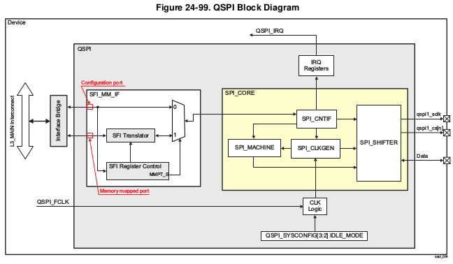
Fig. 3.1 QSPI Block Diagram
Driver Architecture
Following diagram shows the QSPI driver stack:
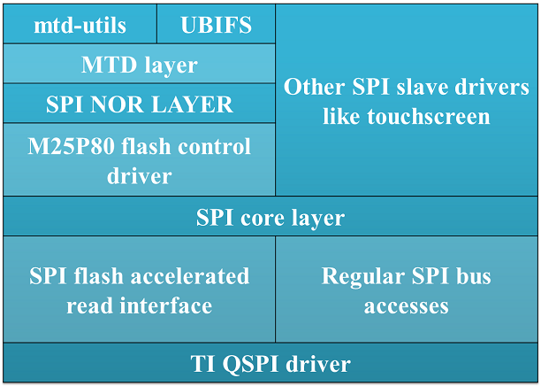
Fig. 3.2 QSPI software stack
QSPI driver can be use both to access SPI flash devices via mtd subsystem or access generic SPI devices (like SPI touchscreen) via SPI framework.
Driver Configuration
Source Location
The source file for QSPI driver can be found at: drivers/spi/spi-ti-qspi.c under Linux kernel source tree.
Kernel Configuration Options
The driver can be built into the kernel or can be compiled as module and loaded into the kernel dynamically.
Enabling QSPI Driver Configurations
Following needs to be enabled to access QSPI flash: TI QSPI controller driver, SPI NOR framework and MTD M25P80 generic serial flash driver in the kernel via menuconfig.
start Linux Kernel Configuration tool.
$ make menuconfig ARCH=arm
To enable QSPI controller driver:
Device Drivers --->
[*] SPI support --->
<*> DRA7xxx QSPI controller support
To enable SPI NOR framework:
Device Drivers --->
<*> Memory Technology Device (MTD) support --->
<*> SPI-NOR device support --->
To enable M25P80 generic SPI flash driver:
Device Drivers --->
<*> Memory Technology Device (MTD) support --->
Self-contained MTD device drivers --->
<*> Support most SPI Flash chips (AT26DF, M25P, W25X, ...)
To enable them as module make <*> as <M>
Enabling UBIFS filesystem support:
File systems --->
[*] Miscellaneous filesystems --->
<*> UBIFS file system support
DT Configuration
Refer to Documentation/devicetree/bindings/spi/ti_qspi.txt under kernel source tree for QSPI controller driver’s DT bindings and their usage.
For generic SPI bus related DT bindings refer to: Documentation/devicetree/bindings/spi/ti_qspi.txt
To configure QSPI flash partitions and flash related DT bindings refer to: Documentation/devicetree/bindings/mtd/jedec,spi-nor.txt and Documentation/devicetree/bindings/mtd/partition.txt
Driver Usage
Load QSPI module using modprobe (this will take care of dependencies and load those modules as well)
$modprobe spi-ti-qspi
This should create /dev/mtdX entries for every partitions defined in DT or via command line arguments. To see all MTD partitions in the system run:
$cat /proc/mtd
dev: size erasesize name
mtd0: 00080000 00010000 "QSPI.U_BOOT"
mtd1: 00080000 00010000 "QSPI.U_BOOT.backup"
mtd2: 00010000 00010000 "QSPI.U-BOOT-SPL_OS"
mtd3: 00010000 00010000 "QSPI.U_BOOT_ENV"
mtd4: 00010000 00010000 "QSPI.U-BOOT-ENV.backup"
mtd5: 00800000 00010000 "QSPI.KERNEL"
mtd6: 036d0000 00010000 "QSPI.FILESYSTEM"
Testing
Using mtd-utils
$ cat /proc/mtd /* Should list QSPI partitions */
$ flash_erase /dev/mtd6 0 0 /* Erase entire /dev/mtd6 */
$ dd if=/dev/random of=tmp_write.txt bs=1 count=num /* num = bytes to write to flash */
$ mtd_debug write /dev/mtd6 0 num tmp_write.txt /* write to num bytes to flash */
$ mtd_debug read /dev/mtd6 0 num tmp_read.txt /* /* read to num bytes to flash */
$ diff tmp_read.txt tmp_write.txt /* should be NULL */
Using dd command
$ cat /proc/mtd /* Should list QSPI partitions */
$ flash_erase /dev/mtd6 0 0 /* Erase entire /dev/mtd6 */
$ dd if=/dev/random of=tmp_write.txt bs=1 count=num /* num = bytes to write to flash */
$ dd if=tmp_write.txt of=/dev/mtd6 bs=num count=1 /* write to num bytes to flash */
$ dd if=/dev/mtd6 of=tmp_read.txt bs=num count=1 /* read to num bytes to flash */
$ diff tmp_read.txt tmp_write.txt /* should be NULL */
Using UBIFS on flash
Make sure UBIFS filesystem is enabled in the kernel refer to this section.
root~# ubiformat /dev/mtd9
ubiformat: mtd9 (nor), size 23199744 bytes (22.1 MiB), 354 eraseblocks of 65536 bytes (64.0 KiB), min. I/O size 1 bytes
libscan: scanning eraseblock 353 -- 100 % complete
ubiformat: 354 eraseblocks are supposedly empty
ubiformat: formatting eraseblock 353 -- 100 % complete
root:~# ubiattach -p /dev/mtd9
[ 270.874428] ubi0: attaching mtd9
[ 270.914131] ubi0: scanning is finished
[ 270.921788] ubi0: attached mtd9 (name "QSPI.file-system", size 22 MiB)
[ 270.928405] ubi0: PEB size: 65536 bytes (64 KiB), LEB size: 65408 bytes
[ 270.935210] ubi0: min./max. I/O unit sizes: 1/256, sub-page size 1
[ 270.941491] ubi0: VID header offset: 64 (aligned 64), data offset: 128
[ 270.948102] ubi0: good PEBs: 354, bad PEBs: 0, corrupted PEBs: 0
[ 270.954215] ubi0: user volume: 0, internal volumes: 1, max. volumes count: 128
[ 270.961602] ubi0: max/mean erase counter: 0/0, WL threshold: 4096, image sequence number: 2077421476
[ 270.970887] ubi0: available PEBs: 350, total reserved PEBs: 4, PEBs reserved for bad PEB handling: 0
[ 270.980204] ubi0: background thread "ubi_bgt0d" started, PID 863
UBI device number 0, total 354 LEBs (23154432 bytes, 22.1 MiB), available 350 LEBs (22892800 bytes, 21.8 MiB), LEB size 65408 bytes (63.9 KiB)
root:~# ubimkvol /dev/ubi0 -N flash_fs -s 20MiB
Volume ID 0, size 321 LEBs (20995968 bytes, 20.0 MiB), LEB size 65408 bytes (63.9 KiB), dynamic, name "flash_fs", alignment 1
root:~# mkdir /mnt/flash
root:~# mount -t ubifs ubi0:flash_fs /mnt/flash/
[ 326.002602] UBIFS (ubi0:0): default file-system created
[ 326.008309] UBIFS (ubi0:0): background thread "ubifs_bgt0_0" started, PID 866
[ 326.027530] UBIFS (ubi0:0): UBIFS: mounted UBI device 0, volume 0, name "flash_fs"
[ 326.035157] UBIFS (ubi0:0): LEB size: 65408 bytes (63 KiB), min./max. I/O unit sizes: 8 bytes/256 bytes
[ 326.044615] UBIFS (ubi0:0): FS size: 20341888 bytes (19 MiB, 311 LEBs), journal size 1046528 bytes (0 MiB, 16 LEBs)
[ 326.055123] UBIFS (ubi0:0): reserved for root: 960797 bytes (938 KiB)
[ 326.061610] UBIFS (ubi0:0): media format: w4/r0 (latest is w4/r0), UUID 828AA98E-3A51-4B35-AD50-9E90144AD4C7, small LPT model
root:~#
Now you can access filesystem at /mnt/flash/
Limitations
- The QSPI supports only dual and quad reads. Dual or quad writes are not supported. In addition, there is no “pass through” mode supported where the data present on the QSPI input is sent to its output
- QSPI IP is designed in such a way that after 4096 word transfer, chip select automatically gets de asserted. As a result of which, the entire flash cannot be read in a single chip select using (Single/Dual/Quad) bit read mode feature. While the serial flash linux framework and flash specification expects the entire read to happen with a single read command in a single chip select. This limitation is not applicable when QSPI is used in memory mapped mode for reads. The QSPI driver by default uses memory mapped reads.
- For writes QSPI uses normal SPI interface instead of memory mapped mode, this is because there is an explicit write enable command that needs to be sent to flash for every page write (256 bytes) which is not handled by SPI_MM_IF.
3.3.4.20. SPI
Introduction
- Serial interface
- Synchronous
- Master-slave configuration (driver supports only master mode)
- Data Exchange - DMA/PIO
SOC Specific Information
| SoC Family | Driver |
|---|---|
| AM335x | McSPI |
| AM437x | McSPI |
| DRA7x | McSPI |
| 66AK2Gx | McSPI |
| 66AK2Lx | Davinci |
| 66AK2Hx | Davinci |
| 66AK2E | Davinci |
Features Not Supported
SoCs using McSPI driver
SPI slave mode isn’t supported
SoCs using Davinci Driver
SPI slave mode isn’t supported
Kernel Configuration
The specific peripheral driver to enable depends on the SoC being used.
Enabling McSPI Driver
Device Drivers --->
[*] SPI support
[*] McSPI driver for OMAP
Enabling DaVinci Driver
Device Drivers --->
[*] SPI support
[*] Texas Instruments DaVinci/DA8x/OMAP-L/AM1x SoC SPI controller
SPI Driver Usecases
There are numerous drivers that can be used to interact with a variety of hardware. From SPI based RTC to SPI based GPIO expander. A list of drivers along with their documentation can be found within the kernel sources. The below section attempts to provide information on SPI based chips that are located on TI’s evms.
Flash Storage
Boards with SPI Flash
| EVM | Part # | Flash Size |
|---|---|---|
| AM335x ICE EVM | W25Q64 | 8 MB |
| K2E EVM | N25Q128A11ESF40F | 16 MB |
| K2HK EVM | N25Q128A11ESF40F | 16 MB |
| K2L EVM | N25Q128A11ESF40F | 16 MB |
Kernel Configuration
Device Drivers --->
<*> Memory Technology Device (MTD) support --->
Self-contained MTD device drivers --->
<*> Support most SPI Flash chips (AT26DF, M25P, W25X, ...)
Reading/Writing to Flash
Determine SPI NOR Partition MTD Identifier
Within the kernel figuring out the mtd device number that is for a particular SPI NOR partition is simple. A user simply needs to view the list of mtd devices along with its name. Below command will provide this information:
cat /proc/mtd
An example of this output performed on the AM571x IDK EVM can be seen below.
dev: size erasesize name
mtd0: 00040000 00010000 "QSPI.SPL"
mtd1: 00100000 00010000 "QSPI.u-boot"
mtd2: 00080000 00010000 "QSPI.u-boot-spl-os"
mtd3: 00010000 00010000 "QSPI.u-boot-env"
mtd4: 00010000 00010000 "QSPI.u-boot-env.backup1"
mtd5: 00800000 00010000 "QSPI.kernel"
mtd6: 01620000 00010000 "QSPI.file-system"
Note the names of these partitions, their sizes (in hex) and offsets (in hex) are determined within the specific board’s device tree file.
flash_erase /dev/mtdX 0 0
Where X is the partition number.
cd /tmp
dd if=/dev/mtd2 of=test.img bs=8k count=1
md5sum test.img
flash_eraseall /dev/mtd4
dd if=test.img of=/dev/mtd4 bs=8k count=1
dd if=/dev/mtd4 of=test1.img bs=8k count=1
md5sum test1.img
Linux Userspace Interface
In situations where a premade SPI driver doesn’t exist or a user wants a simple means to send and receive SPI messages the spidev driver can be used. Spidev provides a user space accessible means to communicate with the SPI interface. Latest documentation regarding spidev driver can be found here.
Spidev allows users to interact with the spi interface in a variety of programming languages that can communicate with kernel ioctls.
Kernel Configuration
Device Drivers --->
[*] SPI support
<*> User mode SPI device driver support
Device Tree
Below is an example of the device tree settings a user would use to enable the spidev driver. Like most drivers for a peripheral, the spidev driver is listed as a subnode of the main SPI peripheral driver.
&spi1 {
status = "okay";
pinctrl-names = "default";
pinctrl-0 = <&spi1_pins_s0>;
spidev@1 {
spi-max-frequency = <24000000>;
reg = <0>;
compatible = "rohm,dh2228fv";
};
};
- Note that reg property for SPI subnodes are usually used to indicate the chip select to use when communicating with a particular driver.
Test Application
In the kernel sources, ./tools/spi/spidev_test.c is a test application within the kernel that can be cross compiled to show a C application interacting with the SPI peripheral.
3.3.4.21. SATA
Introduction
Acronyms & Definitions
| Acronym | Definition |
|---|---|
| SATA | Serial Advanced Technology Attachement |
| PATA | Parallel AT Attachement |
| SSD | Solid State Disk |
| HDD | Hard Disk Drive |
| Gen-1/Gen-2/Gen-3 | Generation of SATA device. |
Features NOT supported
- Gen-3 SATA HDD/SSD is not guaranteed to be supported on OMAP5 and DRA7 due to a silicon bug which prevents correct PHY speed negotiation.
- Aggressive Power management
Supported EVMs
| EVM | Number of Instances |
|---|---|
| AM57 GP EVM | 1 Instance (either eSATA or mSATA) |
| Beagle X15 | 1 Instance (eSATA) |
| DRA74 GP EVM | 1 Instance (SATA) |
Table: caption
Kernel Configuration
Device Drivers --->
<M> Serial ATA and Parallel ATA drivers (libata) --->
<M> AHCI SATA support
<M> Platform AHCI SATA support
Accessing SATA Hard Drive
These instructions assume the SATA hard drive being used has already been partitions. Information on partition the hard drive is beyond the scope of this article.
Kernel
Detecting Hard Drive
Before you can start reading and writing to a partition you first need to know which sdX device is associate with the hard drive. The easiest approach is to use “parted -l”.
This command will show all the various storage medias Linux has detected. The output that will be shown may be quite large if you have sd cards, eMMC, USB thumbdrives, etc.. connected to the board. However, for SATA your only interested in devices that have “(scsi)” at the end of the Model field.
Example output of the command is shown below. Non SATA related output was truncated.
root@am57xx-evm:~# parted -l
...
Model: ATA PLEXTOR PX-64M6M (scsi)
Disk /dev/sda: 64.0GB
Sector size (logical/physical): 512B/512B
Partition Table: msdos
Disk Flags:
Number Start End Size Type File system Flags
1 1049kB 83.9MB 82.8MB primary fat32 boot, lba
2 84.9MB 17.3GB 17.2GB primary fat32
3 17.3GB 64.0GB 46.8GB primary ext2
...
Above the model field shows the name of the particular hard drive and in the disk field it shows the specific device (/dev/sdX) its associated with along with the size. In the above example this Plextor hard drive is associated with “/dev/sda”. The other additional information that can be gathered from the parted -l command is information regarding the various partitions. In the table that has column Number, Start, End, etc... you can see this hard drive has 3 partitions. The command shows various information including the partition size along with the file system type.
This is useful since each partition can be accessed via /dev/sdXY. Where X is the specific disk letter and Y is the partition number. Therefore, the device that is associated with the Plextor hard drive’s second partition is “/dev/sda2” which is a ~17GB FAT32 partition.
Determining Mounted Partition Location
Now its likely if you have partitions on the hard drive that their already been automated. Use “lsblk /dev/sdX” to determine if a partition has been mounted and if so where.
Example output of the command is shown below:
root@am57xx-evm:~# lsblk /dev/sda
NAME MAJ:MIN RM SIZE RO TYPE MOUNTPOINT
sda 8:0 0 59.6G 0 disk
|-sda2 8:2 0 16G 0 part /run/media/sda2
|-sda3 8:3 0 43.6G 0 part
`-sda1 8:1 0 79M 0 part /run/media/sda1
The above output shows the three sda partitions. Under mountpoint it list the directory that the partition has been mounted to. However, a blank entry under mount point indicates the partition has not been mounted.
U-Boot
Information regarding accessing SATA hard drive in U-boot can be found in the Linux Core U-boot User’s Guide SATA Section.
3.3.4.22. NAND
Introduction
TI infrastructure for NAND Flash devices
TI’s SoC interface with NAND Flash devices via on-chip GPMC (General Purpose Memory Controller) interface or via AEMIF depending on the SoC.
For devices that include GPMC: The ECC algorithms required by NAND devices to protect their data, are managed by two independent hardware engines:
- GPMC ECC engine: used for calculating ECC checksum while writing and reading the NAND device.
- ELM ECC engine: used for locating and decoding ECC errors while reading the NAND device.
- NAND subsystem: protocol driver in MTD sub-system for interfacing with NAND flash devices.
For K2L and K2E:
- AEMIF driver: controller driver for AEMIF engine
For all other SoCs:
- GPMC driver: controller driver for GPMC engine
- ELM driver (for applicable SoC) : controller driver for ELM engine.
Supported Features
- NAND devices having:
- bus-width = x8 | x16
- page-size = 2048 | 4096
- block-size = 128k | 256k
- 1-bit Hamming, BCH4, BCH8 and BCH16 ECC schemes.
- Various transfer modes for different use-cases and applications (like Polled, Polled Prefetch, IRQ and DMA).
- NAND boot support for custom non-ONFI compatible NAND devices using NAND-I2C boot-mode (Refer Chapter on Initialization in processor’s TRM).
- Sub-page write
Accessing NAND partitions
Linux
Within the kernel NAND partitions are accessed via mtd devices. Instead are referring to a partition by its name or its offset a user simply needs to specify the NAND partition in question in the form of its mtd device path. Usually in the format of /dev/mtdX where X is the mtd device number.
Determine NAND Partition MTD Identifier
Within the kernel figuring out the mtd device number that is for a particular NAND partition is simple. A user simply needs to view the list of mtd devices along with its name. Below command will provide this information:
cat /proc/mtd
An example of this output performed on the DRA71x EVM can be seen below.
dev: size erasesize name
mtd0: 00010000 00010000 "QSPI.SPL"
mtd1: 00010000 00010000 "QSPI.SPL.backup1"
mtd2: 00010000 00010000 "QSPI.SPL.backup2"
mtd3: 00010000 00010000 "QSPI.SPL.backup3"
mtd4: 00100000 00010000 "QSPI.u-boot"
mtd5: 00080000 00010000 "QSPI.u-boot-spl-os"
mtd6: 00010000 00010000 "QSPI.u-boot-env"
mtd7: 00010000 00010000 "QSPI.u-boot-env.backup1"
mtd8: 00800000 00010000 "QSPI.kernel"
mtd9: 01620000 00010000 "QSPI.file-system"
mtd10: 00020000 00020000 "NAND.SPL"
mtd11: 00020000 00020000 "NAND.SPL.backup1"
mtd12: 00020000 00020000 "NAND.SPL.backup2"
mtd13: 00020000 00020000 "NAND.SPL.backup3"
mtd14: 00040000 00020000 "NAND.u-boot-spl-os"
mtd15: 00100000 00020000 "NAND.u-boot"
mtd16: 00020000 00020000 "NAND.u-boot-env"
mtd17: 00020000 00020000 "NAND.u-boot-env.backup1"
mtd18: 00800000 00020000 "NAND.kernel"
mtd19: 0f600000 00020000 "NAND.file-system"
As you can see above the list of mtd devices may not only include NAND partitions but list other peripherals that create mtd devices also. From the above you can see that if the user wants to access the file-system partition within the NAND then they use /dev/mtd19 to reference the partition. The names of these partitions, their sizes (in hex) and offsets (in hex) are determined within the specific board’s device tree file.
Erasing, Reading and Writing
For the below sections it is important to remember to replaced mtdX with the mtd device that is associated with the particular NAND partition as described in the above section.
flash_erase /dev/mtdX 0 0
The command to write to a NAND partition is below:
nandwrite -p /dev/mtdX <filename>
nanddump /dev/mtdX -f <filename>
The symbol <filename> should be replaced with the name of a file you want to be created that contains with contents of the NAND partition. Note that the above command by default with save to a file the complete contents of the NAND partition. If your interested in only a certain amount of data being dumped additional parameters can be passed to the utility.
Command Line Partitioning
In some situations, partitions defined in device-tree may not be sufficient or correct. Note that once partitions are defined in device-tree and present in a mainline kernel release, they cannot be changed because this breaks users who have existing data on NAND flash and upgrade to new kernel and device-tree. If you are not affected by this issue, you may choose to override partition information passed from device-tree using command line.
In TI kernel releases, MTD command line partitioning support is built as
module. To use it, add something like following to the kernel command
line (passed using bootargs U-Boot variable)
setenv bootargs ${bootargs} cmdlinepart.mtdparts=davinci-nand.0:1m(image)ro,-(free-space)
Note that MTD command line parses breaks if there is space in partition
name. So use “free-space” not “free space”. Change davinci-nand.0 to
the correct device name. You can usually find the name to use from
dmesgoutput
Creating 2 MTD partitions on "davinci-nand.0":
You can also setup new partitions after kernel has booted with old partitions. You will need to re-probe the NAND driver if it has already probed. Something like:
$ modprobe -r davinci_nand
$ modprobe cmdlinepart mtdparts="davinci-nand.0:2m(image)ro,-(free space)"
$ modprobe davinci_nand
davinci_nand module name here may have to be changed based on the
SoC you are using.
U-boot
NAND Based File system
Required Software
Building a UBI file system depends on two applications. Ubinize and mkfs.ubifs which are both provided by Ubuntu’s mtd-utils package (apt-get install mtd-utils). The below instructions are based on version 1.5.0 of mtd-utils although newer version are likely to work.
Building UBI File system
When building a UBI file system you need to have a directory that contains the exact files and directories layout that you plan to use for your file system. This is similar to the files and directories layout you will use to copy a file system onto a SD card for booting purposes. It is important that your file system size is smaller than the file system partition in the NAND.
[ubifs]
mode=ubi
image=<name>.ubifs
vol_id=0
vol_type=dynamic
vol_name=rootfs
vol_flags=autoresize
mkfs.ubifs -r <directory path> -o <name>.ubifs <MKUBIFS ARGS>
ubinize -o <name>.ubi <UBINIZE ARGS> ubinize.cfg
Once these commands are executed <name>.ubi can then be programmed into the NAND’s designated file-system partition.
| Board Name | MKUBIFS Args | UBINIZE Args |
|---|---|---|
| AM335X GP EVM | -F -m 2048 -e 126976 -c 5600 | -m 2048 -p 128KiB -s 512 -O 2048 |
| AM437x GP EVM | -F -m 4096 -e 253952 -c 2650 | -m 4096 -p 256KiB -s 4096 -O 4096 |
| K2E EVM | -F -m 2048 -e 126976 -c 3856 | -m 2048 -p 128KiB -s 2048 -O 2048 |
| K2L EVM | -F -m 4096 -e 253952 -c 1926 | -m 4096 -p 256KiB -s 4096 -O 4096 |
| K2G EVM | -F -m 4096 -e 253952 -c 1926 | -m 4096 -p 256KiB -s 4096 -O 4096 |
| DRA71x EVM | -F -m 2048 -e 126976 -c 8192 | -m 2048 -p 128KiB -s 512 -O 2048 |
Table: Table of Parameters to use for Building UBI filesystem image
Board specific configurations
| EVM | NAND Part # | Size | Bus-Widt h | Block-Si ze (KB) | Page-Siz e (KB) | OOB-Size (bytes) | ECC Scheme | Hardware |
|---|---|---|---|---|---|---|---|---|
| AM335x GP | MT29F2G0 8AB | 256 MB | 8 | 128 | 2 | 64 | BCH 8 | GPMC |
| AM437x GP | MT29F4G0 8AB | 512 MB | 8 | 256 | 4 | 224 | BCH 16 | GPMC |
| AM437x EPOS | MT29F4G0 8AB | 512 MB | 8 | 256 | 4 | 224 | BCH 16 | GPMC |
| DRA71x | MT29F2G1 6AADWP:D | 256 MB | 16 | 128 | 2 | 64 | BCH 8 | GPMC |
| K2G | MT29F2G1 6ABAFAWP :F | 512 MB | 16 | 128 | 2 | 64 | BCH 16 | GPMC |
| K2E | MT29F4G0 8ABBDAH4 D | 1 GB | 8 | 128 | 2 | 64 | TBD | AEMIF |
| K2L | MT29F16G 08ADBCAH 4:C | 512 MB | 8 | 256 | 4 | 224 | TBD | AEMIF | |
Table: NAND Flash Specification Summary
AM43xx GP EVM
On this board, NAND Flash data lines are muxed with eMMC, so either eMMC or NAND can be used enabled at a time. By default NAND is enabled.
AM43xx EPOS EVM
On this board, NAND Flash control lines are muxed with QSPI, Thus either NAND or QSPI-NOR can be used at a time. By default NAND is enabled.
DRA71x EVM
On the board, NAND Flash signals are muxed between NAND, NOR and Video Out signals. Therefore, to have the signals properly muxed for NAND to work Pin 1 (first pin on the left) must be turned on and Pin 2 must be turned off. Pin 1 and 2 must never be switched on at the same time. Doing so may cause damage to the board or SoC.
Configurations (GPMC Specific)
How to enable OMAP NAND driver in Linux Kernel ?
OMAP NAND driver can be enable/disable via Linux Kernel Configuration tool. Enable below Configs to enable MTD Support along with MTD nand driver support
Device Drivers --->
<*> Memory Technology Device (MTD) support --->
[*] Command line partition table parsing
<*> Direct char device access to MTD devices
<*> Caching block device access to MTD devices
<*> NAND Device Support --->
<*> NAND Flash device on OMAP2 and OMAP3
<*> Enable UBI - Unsorted block images --->
Transfer Modes
Choose correct bus transfer mode
- “prefetch-polled” Prefetch polled mode (default)
- “polled” Polled mode, without prefetch
- “prefetch-dma” Prefetch enabled DMA mode
- “prefetch-irq” Prefetch enabled IRQ mode
Transfer mode can be configured in linux-kernel via DT binding <ti,nand-xfer-type> Refer: Linux kernel_docs @ $LINUX/Documentation/devicetree/bindings/mtd/gpmc-nand.txt
DMA vs Non DMA Mode (PIO Mode)
The current NAND subsystem within Linux currently deals with reading a single page from the NAND at a time. Unfortunately, the page size is small enough that the overhead for using the DMA (including Linux DMA software stack) negatively impacts the performance. Based on nand performance tests done in early 2016 using the DMA reduced NAND read and write performance by 10-20% depending on SOC. However, cpu load when using polling via the same NAND test were around 99%. When using DMA mode the CPU load for reading was around 35%-54% and for writing was around 15%-30% depending on SOC.
Performance optimizations on NAND
Tweak NAND device signal timings
Much of the NAND throughput can be improved by matching GPMC signal timings with NAND device present on the board. Although GPMC signal timing configurations are not same as those given in NAND device datasheets, but they can be easily derived based on details given in GPMC Controller functional specification.
- Details of GPMC Signal Timing configurations and how to use them can be found in TI’s Processor TRM
Chapter General Purpose Memory Controller Section Signal Control
- In Linux, GPMC signal timing configurations are specified via DTB.
Refer kernel_docs $LINUX/Documentation/devicetree/bindings/bus/ti-gpmc.txt Some timing configurations like <gpmc,rd-cycle-ns>, <gpmc,wr-cycle-ns> have larger impact on NAND throughput than others.
- In U-boot, GPMC signal timing configurations are specified during GPMC initialization in arch/arm/cpu/armv7/../... mem.c or mem_common.c
gpmc_init() :: struct gpmc_cfg
Tweaking UBIFS
- Specify -o bulk_read while mounting UBIFS (read ahead)
- Tweak Linux VM (kernel knobs for VM)
Additional Resources
3.3.4.23. MMC/SD
Introduction
The multimedia card high-speed/SDIO (MMC/SDIO) host controller provides an interface between a local host (LH) such as a microprocessor unit (MPU) or digital signal processor (DSP) and either MMC, SD® memory cards, or SDIO cards and handles MMC/SDIO transactions with minimal LH intervention.
Main features of the MMC/SDIO host controllers:
- Full compliance with MMC/SD command/response sets as defined in the Specification.
- Support:
- 4-bit transfer mode specifications for SD and SDIO cards
- 8-bit transfer mode specifications for eMMC
- Built-in 1024-byte buffer for read or write
- 32-bit-wide access bus to maximize bus throughput
- Single interrupt line for multiple interrupt source events
- Two slave DMA channels (1 for TX, 1 for RX)
- Designed for low power and Programmable clock generation
- Maximum operating frequency of 48MHz
- MMC/SD card hot insertion and removal
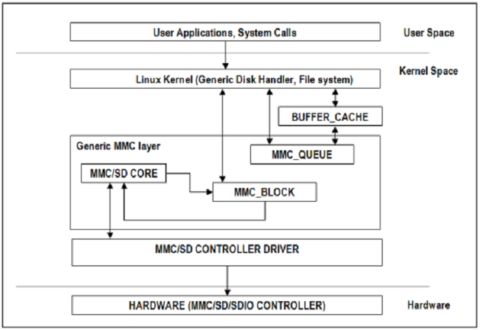
MMC/SD Driver Architecture
References
- JEDEC eMMC Homepage [https://www.jedec.org/category/technology-focus-area/flash-memory-ssds-ufs-emmc]
- SD ORG Homepage [https://www.sdcard.org/home]
Acronyms & Definitions
| Acronym | Definition |
|---|---|
| MMC | Multimedia Card |
| HS-MMC | High Speed MMC |
| SD | Secure Digital |
| SDHC | SD High Capacity |
| SDIO | SD Input/Output |
Table: HSMMC Driver: Acronyms
Features
The SD driver supports following features
- The driver is built in-kernel (part of vmlinux)
- SD cards including SD High Speed and SDHC cards
- Uses block bounce buffer to aggregate scattered blocks
Features NOT supported
- Polling I/O mode
Supported High Speed Modes
| Platform | SDR104 | DDR50 | SDR50 | SDR25 | SDR12 |
|---|---|---|---|---|---|
| DRA74-EVM | Y | Y | Y | Y | Y |
| DRA72-EVM | Y | Y | Y | Y | Y |
| DRA71-EVM | Y | Y | Y | Y | Y |
| DRA72-EVM-REVC | Y | Y | Y | Y | Y |
| AM57XX-EVM | N | N | N | N | N |
| AM57XX-EVM-REVA3 | Y*(1)* | Y*(1)* | Y*(1)* | Y*(1)* | Y*(1)* |
| AM572X-IDK | Y*(1)* | Y*(1)* | Y*(1)* | Y*(1)* | Y*(1)* |
| AM571X-IDK | Y*(1)* | Y*(1)* | Y*(1)* | Y*(1)* | Y*(1)* |
Table: MMC1/SD
*(1)* - Does not have power cycle support. So if a card fails to enumerate in UHS mode, it doesn’t fall back to high speed mode.
Important Info: Certain UHS cards doesn’t enumerate in UHS cards. Find the list of functional UHS cards here: https://processors.wiki.ti.com/index.php/Linux_Core_MMC/SD_User%27s_Guide#Testing_Information
Known Workaround: For cards which doesn’t enumerate in UHS mode, removing the PULLUP resistor in CLK line and changing the GPIO to PULLDOWN increases the frequency in which the card enumerates in UHS modes.
| Platform | DDR | HS200 |
|---|---|---|
| DRA74-EVM | Y | Y |
| DRA72-EVM | Y | Y |
| DRA71-EVM | Y | Y |
| DRA72-EVM-REVC | Y | Y |
| AM57XX-EVM | Y | N |
| AM57XX-EVM-REVA3 | Y | N |
| AM572X-IDK | Y | N |
| AM571X-IDK | Y | N |
Table: MMC2/EMMC
Driver Configuration
The default kernel configuration enables support for MMC/SD(built-in to kernel). OMAP MMC/SD driver is used.
The selection of MMC/SD/SDIO driver can be modified as follows: start Linux Kernel Configuration tool.
$ make menuconfig ARCH=arm
- Select Device Drivers from the main menu.
...
...
Kernel Features --->
Boot options --->
CPU Power Management --->
Floating point emulation --->
Userspace binary formats --->
Power management options --->
[*] Networking support --->
Device Drivers --->
...
...
Building into Kernel
- Select MMC/SD/SDIO card support from the menu.
...
...
[*] USB support --->
< > Ultra Wideband devices (EXPERIMENTAL) --->
<*> MMC/SD/SDIO card support --->
< > Sony MemoryStick card support (EXPERIMENTAL) --->
...
...
- Select OMAP HSMMC driver
...
[ ] MMC debugging
[ ] Assume MMC/SD cards are non-removable (DANGEROUS)
*** MMC/SD/SDIO Card Drivers ***
<*> MMC block device driver
[*] Use bounce buffer for simple hosts
...
<*> TI OMAP High Speed Multimedia Card Interface support
...
Building as Loadable Kernel Module
- To build the above components as modules, press ‘M’ key after navigating to config entries preceded with ‘< >’ as shown below:
...
...
[*] USB support --->
< > Ultra Wideband devices (EXPERIMENTAL) --->
<M> MMC/SD/SDIO card support --->
< > Sony MemoryStick card support (EXPERIMENTAL) --->
...
- Select OMAP HSMMC driver to be built as module
...
[ ] MMC debugging
[ ] Assume MMC/SD cards are non-removable (DANGEROUS)
*** MMC/SD/SDIO Card Drivers ***
<*> MMC block device driver
[*] Use bounce buffer for simple hosts
...
<*> TI OMAP High Speed Multimedia Card Interface support
...
- After doing module selection, exit and save the kernel configuration when prompted.
- Now build the kernel and modules form Linux build host as
$ make uImage
$ make modules
- Following modules will be built
mmc_core.ko
mmc_block.ko
omap_hsmmc.ko
- Boot the newly built kernel and transfer the above mentioned .ko files to the filesystem
- Navigate to the directory containing these modules and insert them form type the following commands in console to insert the modules in specified order:
# insmod mmc_core.ko
# insmod mmc_block.ko
# insmod omap_hsmmc.ko
- If ‘udev’ is running and the SD card is already inserted, the devices nodes will be created and filesystem will be automatically mounted if exists on the card.
Suspend to Memory support
This driver supports suspend to memory functionality. To use the same, the following configuration is enabled by default.
- Select Device Drivers from the main menu.
...
...
Kernel Features --->
Boot options --->
CPU Power Management --->
Floating point emulation --->
Userspace binary formats --->
Power management options --->
[*] Networking support --->
Device Drivers --->
...
...
- Select MMC/SD/SDIO card support from the menu.
...
...
[*] USB support --->
< > Ultra Wideband devices (EXPERIMENTAL) --->
<*> MMC/SD/SDIO card support --->
< > Sony MemoryStick card support (EXPERIMENTAL) --->
...
...
- Select Assume MMC/SD cards are non-removable option.
...
[ ] MMC debugging
[*] Assume MMC/SD cards are non-removable (DANGEROUS)
*** MMC/SD/SDIO Card Drivers ***
<*> MMC block device driver
[*] Use bounce buffer for simple hosts
...
<*> TI OMAP High Speed Multimedia Card Interface support
...
Enabling eMMC Card Background operations support
This can be done using the “mmc-utils” tool from user space or using the “mmc” command in U-boot.
Command to enable bkops from userspace using mmc-utils, assuming eMMC instance to be mmcblk0
root@dra7xx-evm:mmc bkops enable /dev/mmcblk0
You can find the instance of eMMC by reading the ios timing spec form debugfs
root@dra7xx-evm:~# cat /sys/kernel/debug/mmc0/ios
----
timing spec: 9 (mmc HS200)
---
or by looking for boot partitions, eMMC has two bootpartitions mmcblk<x>boot0 and mmcblk<x>boot1
root@dra7xx-evm:/# ls /dev/mmcblk*boot*
/dev/mmcblk0boot0 /dev/mmcblk0boot1
| FUNCTIONAL UHS CARDS |
|---|
| ATP 32GB UHS CARD AF32GUD3 |
| STRONTIUM NITRO 466x UHS CARD |
| SANDISK EXTREME UHS CARD |
| SANDISK ULTRA UHS CARD |
| SAMSUNG EVO+ UHS CARD |
| SAMSUNG EVO UHS CARD |
| KINGSTON UHS CARD (DDR mode) |
| TRANSCEND PREMIUM 400X UHS CARD (Non fatal error and then it re-enumerates in UHS mode) |
| FUNCTIONAL (WITH LIMITED CAPABILITY) UHS CARD |
|---|
| SONY UHS CARD - Voltage switching fails and enumerates in high speed |
| GSKILL UHS CARD - Voltage switching fails and enumerates in high speed |
| PATRIOT 8G UHS CARD - Voltage switching fails and enumerates in high speed |
3.3.4.24. UART
UART Driver Overview
The UART Driver enables the UART’s available on the device. The driver configures the UART hardware and interfaces with a number of standard linux tools (ex. stty, minicom, etc.) to enable the configuration and usage of the hardware. The H/W UARTs available will vary by SoC and system configuration.
Overview
The UART driver can be used to send/receive raw ASCII characters from the User Interface as shown by the below diagram.
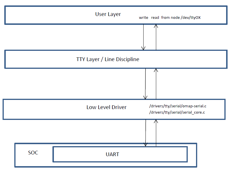
User Layer
The UART driver leverages the TTY framework within Linux. This framework uses typical file I/O operations to interact with the UART. This interface allows userspace modules to easily be developed to read/write the /dev/ttyxx to exchange data over the UART. Since this is a very common Linux framework, there are many standard tools that can be used to interact with it. These tools, like stty, minicom, picocom, and many others, can easily be used to exercise a UART for data exchange.
Features
- Exposes UART to User Space via /dev/tty*
- Supports multiple baud rates and UART capabilities
- Hardware Flow Control
3.3.4.25. MUSB
Quick Start Guide
This section is a quick guide on how to start using usb ports on TI platform with supplied pre-built binaries. Please refer to USB Quick Start
Introduction
The USB User’s Guide provides information about
- Overview of USB hardware and software
- Supported linux driver features for USB host and device mode of operation
- The Linux USB configuration through menuconfig. Please refer to USB configuration
Hardware Overview
USBSS Overview
- The USB subsystem includes
- Two instances of USB (Mentor Graphic’s USB2.0 OTG) controllers. Each MUSB controller supports USB 1.1 and USB 2.0 standard.
- CPPI 4.1 compliant DMA controller sub-module with 30 RX and 30 TX simultaneous DMA channels
- CPPI 4.1 DMA scheduler
- CPPI Queue Manager module with 92 queues for queuing/dequeuing packets
- Interfaces to the CPU via 3 OCP interfaces
- Master OCP HP interface for the DMA (for data transfers)
- Master OCP HP interface for the Queue manager (to manage CPPI descriptors)
- Slave OCP MMR interface (for CPU to access USBSS/MUSB registers)
- Signals the standard Charge Pump (part of EVM BOM) for VBUS 5V generation
MUSB Controller Overview
The salient features of the MUSB USB2.0 OTG controller are:
- High/full speed operation as USB peripheral.
- High/full/low speed operation as Host controller.
- Compliant with OTG spec.
- 15 Transmit and 15 Receive Endpoints other than the mandatory Control Endpoint 0.
- Double buffering support in FIFO.
- Support for high bandwidth Isochronous transfer
- 32 Kilobytes of Endpoint FIFO RAM for USB packet buffering.
- Interfaced with CPPI4.1 DMA controller with 15 Rx and 15 Tx channels (for each usb controller).
- Defer interrupt enable feature is supported for each packet descriptor of cppi-dma.
Software Overview
Mentor graphics controller driver (or MUSB driver)
The MUSB driver is implemented on top of Mentor controller IP which supports all the speeds (High, Full and Low). AM33XX USBOTG subsytem uses CPPI 4.1 DMA for all the transfers. The musb driver conforms to linux usb framework and supports both PIO and DMA mode of operation. The musb host controller driver (HCD) binds the controller hardware to linux usb core stack. The musb device or gadget controller driver binds the controller hardware and specific gadget driver (filestorage, cdc/rndis etc).
Linux USB Stack Architecture
As shown in the figure, linux usb stack is a layered architecture, with musb controller at the lowest layer, the musb host/device controller driver binds the musb controller hardware to linux usb stack framework. The CPPI4.1 DMA controller driver is responsible for transmit/receive of packets over the musb endpoints.
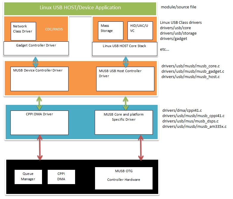
Driver Features List
- The Mentor USB driver can be built as module or built-in to kernel
- Support both PIO and DMA mode (The DMA mode not applicable for control endpoint)
- Support two instances musb controller in otg mode (both usb0 and usb1 controller in otg mode. This will allow host or device operation on each port simultaneously.
The driver supports the following features for USB Host (AM33XX)
| Host Mode Feature | AM33xx |
|---|---|
| HUB class support | Yes |
| Human Interface Class (HID) | Yes |
| Mass Storage Class (MSC) _ | Yes |
Table:
The driver supports the following features for USB Gadget (AM33XX)
| Gadget Mode Feature | AM33xx |
|---|---|
| Mass Storage Class (MSC) | Yes |
| USB Networking - RNDIS | Yes |
| USB Networking - CDC | Yes |
Table:
The driver supports the following features for Dual host/gadget (AM33xx)
| Dual Mode Feature | AM33x |
|---|---|
| USB0 as OTG, USB1 as OTG | Yes |
Table:
Not verified features of AM33xx
| Not verified features | am33x |
|---|---|
| Wifi support | Not verified |
| Serial device | Not verified |
Table:
Known limitations
- musb_am335x.ko can’t be removed (and we don’t allow that to happen) to workaround a known hwmod issue.
- multi-gadget cannot be used on OMAP-L138 because of lack of sufficient number of endpoints to support multiple functions
- high bandwidth ISO cannot be supported on OMAP-L138. On trying a high bandwidth ISO transfer, you should see message of the form:
musb-hdrc musb-hdrc.1.auto: high bandwidth iso (3x896) not supported
This behaviour is expected.
References
- For more details about EVM, please refer to EVM reference manual.
- The Mentor USB driver can be built as module or built into kernel. For more information refer to USB configuration
3.3.4.26. DWC3
Introduction
DWC3 is a SuperSpeed (SS) USB 3.0 Dual-Role-Device (DRD) from Synopsys.
Main features of DWC3:
The SuperSpeed USB controller features:
- Dual-role device (DRD) capability:
- Same programming model for SuperSpeed (SS), High-Speed (HS), Full-Speed (FS), and Low-Speed (LS)
- Internal DMA controller
- LPM protocol in USB 2.0 and U0, U1, U2, and U3 states for USB 3.0
TI SoC Integration
DWC3 is integrated in OMAP5, DRA7x and AM437x SoCs from TI.
OMAP5 (omap5-uevm)
The following diagram depicts dwc3 integration in OMAP5. The ID and VBUS events are sensed by a companion device (palmas). The palmas-usb driver (drivers/extcon/extcon-palmas.c) notifies the events to OMAP glue driver (driver/usb/dwc3/dwc3-omap.c) via the extcon framework. The glue driver writes the events to the software mailbox present in DWC3 glue (SS USB OTG controller module in the diagram) which interrupts the core using UTMI+ signals.
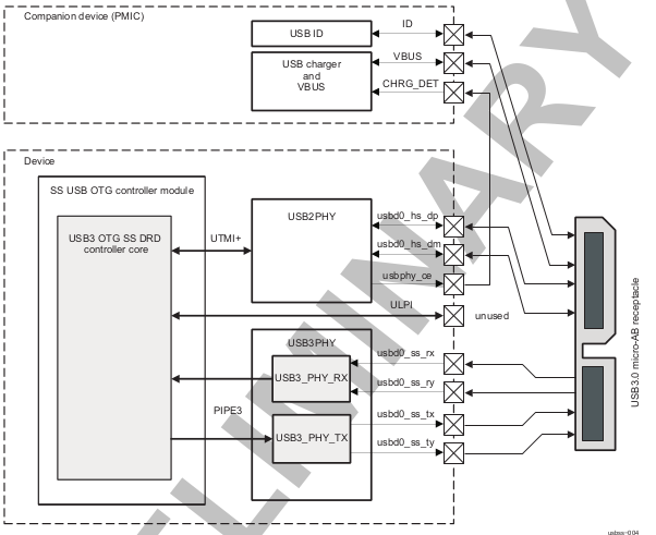
DRA7x/AM57x
The above diagram also depicts dwc3 integration in DRA7x/AM57x. Some boards provide VBUS and ID events over GPIO whereas some provide ID over GPIO and VBUS through Power Management IC (palmas).
- DRA7-evm (J6-evm) and DRA72-evm (J6-eco) boards have ID detection but no VBUS detection support. ID detection is provided through GPIO expander (PCF8574).
- DRA71-evm (J6entry-evm) board has VBUS and ID detection support. Both ID and VBUS detection are provided through GPIO expander (PCF8574).
On these boards, the GPIO driver (drivers/extcon/extcon-usb-gpio.c) notifies the ID and VBUS events to the OMAP dwc3 glue (drivers/usb/dwc3/dwc3-omap.c) via the extcon framework.
All DRA7x boards use USB1 port as Super-Speed dual-role port and USB2 port High-Speed Host port (Type mini-A). You will need a mini-A to Type-A adapter to use the Host port.
AM57x (BeagleBoard-x15/AM57xx-evm/AM57xx-IDK)
- BeagleBoard-x15/AM57xx-evm use USB1 as Super-Speed host port and have a on-board Super-Speed hub which provides 3 Super-Speed Host (Type-A) ports. USB2 is used as High-Speed peripheral port. VBUS detection for USB2 port is provided through Power Management IC (palmas). The palmas USB driver (drivers/extcon/extcon-palmas.c) notifies the VBUS event to the OMAP dwc3 glue (drivers/usb/dwc3/dwc3-omap.c) via the extcon framework.
- AM57xx-IDK boards use USB1 as a High-Speed Host port (Type-A) and USB2 as a High-Speed dual-role port. ID detection for USB2 is provided via GPIO whereas VBUS detection is provided through the PMIC (palmas). The palmas USB driver (drivers/extcon/extcon-palmas.c) notifies both VBUS and ID events to the OMAP dwc3 glue (drivers/usb/dwc3/dwc3-omap.c) via the extcon framework.
AM437x
The following diagram depicts dwc3 integration in AM437x. Super-Speed is not supported so maximum speed is high-speed. VBUS and ID detection is done by the internal PHY, so companion device is not needed. DWC3 controller uses HW UTMI mode to get the VBUS and ID events and the glue driver (omap-dwc3.c) does not need to write to the software mailbox to notify the events to the dwc3 core.
- On AM437x-gp-evm, AM437x-epos-evm and AM437x-sk-evm, USB0 port is used as dual-role port and USB1 port is used as Host port (Type-A).
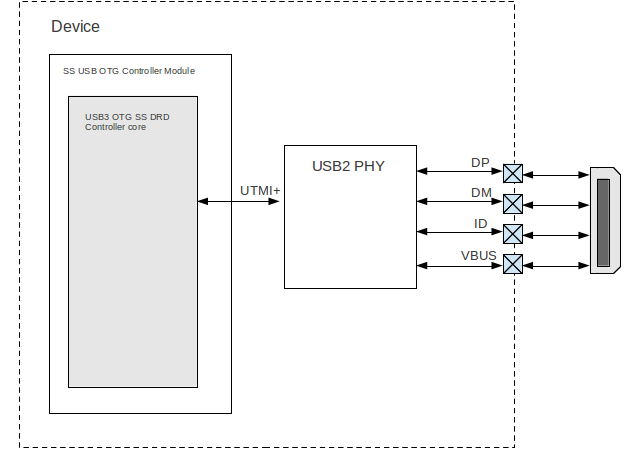
Features NOT supported
- Full OTG is not supported. Only dual-role mode is supported.
Driver Configuration
The default kernel configuration enables support for USB_DWC3, USB_DWC3_OMAP (the wrapper driver), USB_DWC3_DUAL_ROLE.
The selection of DWC3 driver can be modified as follows: start Linux Kernel Configuration tool.
$ make menuconfig ARCH=arm
- Select Device Drivers from the main menu.
...
...
Kernel Features --->
Boot options --->
CPU Power Management --->
Floating point emulation --->
Userspace binary formats --->
Power management options --->
[*] Networking support --->
Device Drivers --->
...
...
Building into Kernel
- Select USB support from the menu.
...
Multimedia support --->
Graphics support --->
<M> Sound card support --->
HID support --->
[*] USB support --->
< > Ultra Wideband devices ----
<*> MMC/SD/SDIO card support --->
...
- Enable Host-side support and Gadget support
...
<M> Support for Host-side USB
...
<M> USB Gadget Support
...
- Select DesignWare USB3 DRD Core Support and Texas Instruments OMAP5 and similar Platforms
...
<M> DesignWare USB3 DRD Core Support
DWC3 Mode Selection (Dual Role mode) --->
*** Platform Glue Driver Support ***
<M> Texas Instruments OMAP5 and similar Platforms
...
- Select Bus devices OMAP2SCP driver
...
-*- OMAP INTERCONNECT DRIVER
<*> OMAP OCP2SCP DRIVER
...
- Select the PHY Subsystem for OMAP5, DRA7x and AM437x
...
[*] Reset Controller Support --->
< > FMC support ---->
PHY Subsystem --->
...
- Select the OMAP CONTRO PHY driver, OMAP USB2 PHY driver for OMAP5, DRA7 and AM437x
- Select OMAP PIPE3 PHY driver for OMAP5 and DRA7x
...
-*- PHY Core
-*- OMAP CONTROL PHY Driver
<*> OMAP USB2 PHY Driver
<*> TI PIPE3 PHY Driver
...
- Select ‘xHCI HCD (USB 3.0) SUPPORT’ from menuconfig in ‘USB support’
< > Support WUSB Cable Based Association (CBA)
*** USB Host Controller Drivers ***
...
<*> xHCI HCD (USB 3.0) support
...
- Select ‘USB Gadget Support —>’ from menuconfig in ‘USB support’ and select the needed gadgets. (By default all gadgets are made as modules)
--- USB Gadget Support
[*] Debugging messages (DEVELOPMENT)
[ ] Verbose debugging Messages (DEVELOPMENT)
[*] Debugging information files (DEVELOPMENT)
[*] Debugging information files in debugfs (DEVELOPMENT)
(2) Maximum VBUS Power usage (2-500 mA)
(2) Number of storage pipeline buffers
USB Peripheral Controller --->
<M> USB Gadget Drivers
< > USB functions configurable through configfs
<M> Gadget Zero (DEVELOPMENT)
<M> Audio Gadget
[ ] UAC 1.0 (Legacy)
<M> Ethernet Gadget (with CDC Ethernet support)
[*] RNDIS support
[ ] Ethernet Emulation Model (EEM) support
<M> Network Control Model (NCM) support
<M> Gadget Filesystem
<M> Function Filesystem
[*] Include configuration with CDC ECM (Ethernet)
[*] Include configuration with RNDIS (Ethernet)
[*] Include 'pure' configuration
<M> Mass Storage Gadget
<M> Serial Gadget (with CDC ACM and CDC OBEX support)
<M> MIDI Gadget
<M> Printer Gadget
<M> CDC Composite Device (Ethernet and ACM)
<M> CDC Composite Device (ACM and mass storage)
<M> Multifunction Composite Gadget
[*] RNDIS + CDC Serial + Storage configuration
[*] CDC Ethernet + CDC Serial + Storage configuration
<M> HID Gadget
<M> HID Gadget
<M> EHCI Debug Device Gadget
EHCI Debug Device mode (serial) --->
<M> USB Webcam Gadget
Configuring DWC3 in gadget only
set ‘dr_mode’ as ‘peripheral’ in respective board dts files present in arch/arm/boot/dts/
- omap5-uevm.dts for OMAP5
- dra7-evm.dts for DRA7x
- am4372.dtsi for AM437x
Example: To configure both the ports of DRA7 as gadget (default usb2 is configured as 'host')
arch/arm/boot/dts/dra7-evm.dts
&usb1 {
dr_mode = "peripheral";
pinctrl-names = "default";
pinctrl-0 = <&usb1_pins>;
};
&usb2 {
dr_mode = "peripheral";
pinctrl-names = "default";
pinctrl-0 = <&usb2_pins>;
};
Configuring DWC3 in host only
set ‘dr_mode’ as ‘host’ in respective board dts files present in arch/arm/boot/dts/
- omap5-uevm.dts for OMAP5
- dra7-evm.dts for DRA7x
- am4372.dtsi for AM437x
Example: To configure both the ports of DRA7 as host (default usb1 is configured as 'otg')
arch/arm/boot/dts/dra7-evm.dts
&usb1 {
dr_mode = "host";
pinctrl-names = "default";
pinctrl-0 = <&usb1_pins>;
};
&usb2 {
dr_mode = "host";
pinctrl-names = "default";
pinctrl-0 = <&usb2_pins>;
};
Testing
Host Mode
Selecting cables
OMAP5-uevm
OMAP5-evm has a single Super-Speed micro AB port provided by the DWC3 controller. To use it in host mode a OTG adapter (Micro USB 3.0 9-Pin Male to USB 3.0 Female OTG Cable) like below should be used. The ID pin within the adapter must be grounded. Some of the adapters available in the market don’t have ID pin grounded. If the ID pin is not grounded the dual-role port will not switch from peripheral mode to host mode.
DRA7x-evm
DRA7x-evm has 2 USB ports provided by the DWC3 controllers. USB1 is a Super-Speed port and USB2 is a High-Speed port. USB1 is by default configured in dual-role mode and USB2 is configured in host mode.
For connecting a device to the USB2 port use a mini-A to Type-A OTG adapter cable like this. The ID pin within the adapter cable must be grounded.
For using the USB1 port in host mode use a Super-Speed OTG adapter cable similar to the one used in OMAP5.
AM437x
AM437x has two USB ports. USB0 is a host port and USB1 is a dual-role port.
The USB0 host port has a standard A female so no special cables needed. To use the USB1 port in host mode a micro OTG adapter cable is required like below.
Example
Connecting a USB2 pendrive to DRA7x gives the following prints
root@dra7xx-evm:~# [ 479.385084] usb 1-1: new high-speed USB device number 2 using xhci-hcd
[ 479.406841] usb 1-1: New USB device found, idVendor=054c, idProduct=05ba
[ 479.413911] usb 1-1: New USB device strings: Mfr=1, Product=2, SerialNumber=3
[ 479.422320] usb 1-1: Product: Storage Media
[ 479.426901] usb 1-1: Manufacturer: Sony
[ 479.430949] usb 1-1: SerialNumber: CB5001212140006303
[ 479.437774] usb 1-1: ep 0x81 - rounding interval to 128 microframes, ep desc says 255 microframes
[ 479.447454] usb 1-1: ep 0x2 - rounding interval to 128 microframes, ep desc says 255 microframes
[ 479.458124] usb-storage 1-1:1.0: USB Mass Storage device detected
[ 479.465355] scsi1 : usb-storage 1-1:1.0
[ 480.784475] scsi 1:0:0:0: Direct-Access Sony Storage Media 0100 PQ: 0 ANSI: 4
[ 480.801677] sd 1:0:0:0: [sda] 61046784 512-byte logical blocks: (31.2 GB/29.1 GiB)
[ 480.820740] sd 1:0:0:0: [sda] Write Protect is off
[ 480.825794] sd 1:0:0:0: [sda] Mode Sense: 43 00 00 00
[ 480.832797] sd 1:0:0:0: [sda] No Caching mode page found
[ 480.838574] sd 1:0:0:0: [sda] Assuming drive cache: write through
[ 480.852070] sd 1:0:0:0: [sda] No Caching mode page found
[ 480.857672] sd 1:0:0:0: [sda] Assuming drive cache: write through
[ 480.865873] sda: sda1
[ 480.874068] sd 1:0:0:0: [sda] No Caching mode page found
[ 480.879839] sd 1:0:0:0: [sda] Assuming drive cache: write through
[ 480.886434] sd 1:0:0:0: [sda] Attached SCSI removable disk
Device Mode
Mass Storage Gadget
In gadget mode standard USB cables with micro plug should be used.
Example: To use ramdisk as a backing store use the following
# mkdir /mnt/ramdrive
# mount -t tmpfs tmpfs /mnt/ramdrive -o size=600M
# dd if=/dev/zero of=/mnt/ramdrive/vfat-file bs=1M count=600
# mkfs.ext2 -F /mnt/ramdrive/vfat-file
# modprobe g_mass_storage file=/mnt/ramdrive/vfat-file
In order to see all other options supported by g_mass_storage, just run modinfo command:
# modinfo g_mass_storage
filename: /lib/modules/3.17.0-rc6-00455-g0255b03-dirty/kernel/drivers/usb/gadget/legacy/g_mass_stor
age.ko
license: GPL
author: Michal Nazarewicz
description: Mass Storage Gadget
srcversion: 3050477C3FFA3395C8D79CD
depends: usb_f_mass_storage,libcomposite
intree: Y
vermagic: 3.17.0-rc6-00455-g0255b03-dirty SMP mod_unload modversions ARMv6 p2v8
parm: idVendor:USB Vendor ID (ushort)
parm: idProduct:USB Product ID (ushort)
parm: bcdDevice:USB Device version (BCD) (ushort)
parm: iSerialNumber:SerialNumber string (charp)
parm: iManufacturer:USB Manufacturer string (charp)
parm: iProduct:USB Product string (charp)
parm: file:names of backing files or devices (array of charp)
parm: ro:true to force read-only (array of bool)
parm: removable:true to simulate removable media (array of bool)
parm: cdrom:true to simulate CD-ROM instead of disk (array of bool)
parm: nofua:true to ignore SCSI WRITE(10,12) FUA bit (array of bool)
parm: luns:number of LUNs (uint)
parm: stall:false to prevent bulk stalls (bool)
Note: The USB Mass Storage Specification requires us to pass a valid iSerialNumber of 12 alphanumeric digits, however g_mass_storage will not generate one because the Kernel has no way of generating a stable and valid Serial Number. If you want to pass USB20CV and USB30CV MSC tests, pass a valid iSerialNumber argument.
USB 2.0 Test Modes
The Universal Serial Bus 2.0 Specification defines a set of Test Modes used to validate electrical quality of Data Lines pair (D+/D-). There are two ways of entering these Test Modes with DWC3.
- Sending properly formatted SetFeature(TEST) Requests to the device (see USB2.0 spec for details)
This is the preferred (and Standard) way of entering USB 2.0 Test Modes. However, it’s not always that we will have a functioning USB Host to issue such requests.
- Using a non-standard DebugFS interface (see below for details)
Any time we don’t have a functioning Host on the Test Setup and still want to enter USB 2.0 Test Modes, we can use this non-standard interface for that purpose. One such use-case is for low level USB 2.0 Eye Diagram testing where the DUT (Device Under Test) is connected to an oscilloscope through a test fixture.
Non-Standard DebugFS Interface
DWC3 Driver exposes a few testing and development tools through the Debug File System. In order to use it, you must first mount that file system in case it’s not mounted yet. Below, we show an example session on AM437x.
# mount -t debugfs none /sys/kernel/debug
# cd /sys/kernel/debug
# ls
48390000.usb dri memblock regulator ubifs
483d0000.usb extfrag mmc0 sched_features usb
asoc fault_around_bytes omap_mux sleep_time wakeup_sources
bdi gpio pinctrl suspend_stats
clk hid pm_debug tracing
dma_buf kprobes regmap ubi
Note the two directories terminated with .usb. Those are the two instances available on AM437x devices, 48390000.usb is USB1 and 483d0000.usb is USB2. Both of those directories contain the same thing, we will use 48390000.usb for the purposes of illustration.
# cd 48390000.usb
# ls
link_state mode regdump testmode
link_state
Shows the current USB Link State
# cat link_state
U0
mode
Shows the current mode of operation. Available options are host, device, otg. It can also be used to dynamically change the mode by writing to this file any of the available options. Dynamically changing the mode of operation can be useful for debug purposes but this should never be used in production.
# cat mode
device
# echo host > mode
# cat mode
host
# echo device > mode
# cat mode
device
regdump
Shows a dump of all registers of DWC3 except for XHCI registers which are owned by the xhci-hcd driver.
# cat regdump
GSBUSCFG0 = 0x0000000e
GSBUSCFG1 = 0x00000f00
GTXTHRCFG = 0x00000000
GRXTHRCFG = 0x00000000
GCTL = 0x25802004
GEVTEN = 0x00000000
GSTS = 0x3e800002
GSNPSID = 0x5533240a
GGPIO = 0x00000000
GUID = 0x00031100
GUCTL = 0x02008010
GBUSERRADDR0 = 0x00000000
GBUSERRADDR1 = 0x00000000
GPRTBIMAP0 = 0x00000000
GPRTBIMAP1 = 0x00000000
GHWPARAMS0 = 0x402040ca
GHWPARAMS1 = 0x81e2493b
GHWPARAMS2 = 0x00000000
GHWPARAMS3 = 0x10420085
GHWPARAMS4 = 0x48a22004
GHWPARAMS5 = 0x04202088
GHWPARAMS6 = 0x08800c20
GHWPARAMS7 = 0x03401700
GDBGFIFOSPACE = 0x00420000
GDBGLTSSM = 0x01090460
GPRTBIMAP_HS0 = 0x00000000
GPRTBIMAP_HS1 = 0x00000000
GPRTBIMAP_FS0 = 0x00000000
GPRTBIMAP_FS1 = 0x00000000
GUSB2PHYCFG(0) = 0x00002500
GUSB2PHYCFG(1) = 0x00000000
GUSB2PHYCFG(2) = 0x00000000
GUSB2PHYCFG(3) = 0x00000000
GUSB2PHYCFG(4) = 0x00000000
GUSB2PHYCFG(5) = 0x00000000
GUSB2PHYCFG(6) = 0x00000000
GUSB2PHYCFG(7) = 0x00000000
GUSB2PHYCFG(8) = 0x00000000
GUSB2PHYCFG(9) = 0x00000000
GUSB2PHYCFG(10) = 0x00000000
GUSB2PHYCFG(11) = 0x00000000
GUSB2PHYCFG(12) = 0x00000000
GUSB2PHYCFG(13) = 0x00000000
GUSB2PHYCFG(14) = 0x00000000
GUSB2PHYCFG(15) = 0x00000000
GUSB2I2CCTL(0) = 0x00000000
GUSB2I2CCTL(1) = 0x00000000
GUSB2I2CCTL(2) = 0x00000000
GUSB2I2CCTL(3) = 0x00000000
GUSB2I2CCTL(4) = 0x00000000
GUSB2I2CCTL(5) = 0x00000000
GUSB2I2CCTL(6) = 0x00000000
GUSB2I2CCTL(7) = 0x00000000
GUSB2I2CCTL(8) = 0x00000000
GUSB2I2CCTL(9) = 0x00000000
GUSB2I2CCTL(10) = 0x00000000
...
A better use for this is, if you know the register name you’re looking for, by using grep we can reduce the amount of output. Assuming we want to check register DCTL we could:
# grep DCTL regdump
DCTL = 0x8c000000
testmode
Shows current USB 2.0 Test Mode. Can also be used to enter such test modes in situations where we can’t issue proper SetFeature(TEST) requests. Available options are test_j, test_k, test_se0_nak, test_packet, test_force_enable. The only way to exit the test modes is through a USB Reset.
# cat testmode
no test
# echo test_packet > testmode
# cat testmode
test_packet
Other Resources
For general Linux USB subsystem - Usbgeneralpage
USB Debugging - elinux.org/images/1/17/USB_Debugging_and_Profiling_Techniques.pdf
3.3.4.27. VPE
Introduction
- This page gives a basic description of VPE mem to mem video IP found in devices, the linux kernel drivers which implement it, how to build the drivers as modules or built-in, and how one can test and use the drivers.
- The driver described here is the VPE v4l2 mem-2-mem driver.
- The guide applies to both 3.12 and the current mainline kernel. Currently, DRA7x requires additional patches for hwmod and DT support for mainline.
- For a generic linux kernel guide, try:
http://processors.wiki.ti.com/index.php/Linux_Kernel_Users_Guide
VPE Supported Devices
DRA7x evm, AM57xx evm
Driver Features
Video processing Engine(VPE) supports following formats for scaling, csc and deinterlacing:
- Supported Input formats: NV12, YUYV, UYVY
- Supported Output formats: NV12, YUYV, UYVY, RGB24, BGR24, ARGB24, ABGR24
- Scaler supports
- Horizontal up-scaling up to 8x and Downscaling up to 4x using Pre-decimation filter.
- Vertical up-scaling up to 8x and Polyphase down-scaling up to 4x followed by RAV scaling.
- V4L2 Multiplanar ioctl() supported.
- Multiple V4L2 device context supported.
- v4l2 m2m related ioctls.
Changes from 3.12 to 3.15
- Changes in 3.13:
- Basic VPE driver introduced with DEI support.
- Changes in 3.14:
- Support added for scaler and color space converter.
- Changes in 3.15:
- Misc fixes found during testing.
Unsupported Features/Limitations
- Following formats are not supported : YUV444, YVYU, VYUY, NV16, NV61, NV21, 16bit and Lower RGB formats are not supported.
- Passing of custom scaler and CSC coeffficients through user space are not supported.
- Only Linear scaling is supported without peaking and trimming.
- Deinterlacer does not support film mode detection.
- VPE functional clock is restricted to 152Mhz due to HW constraints.
Hardware Architecture
VPE(Video Processing Engine) is an IP found on DRA7xx, and in some past TI multimedia SoCs which don’t have baseport support in the mainline kernel.
VPE is a memory to memory block used for performing de-interlacing, scaling and color conversion on input buffers. It’s primarily used to de-interlace decoded DVD/Blu Ray video buffers, and provide the content to progressive display or do some other post processing. VPE can also be used for other tasks like fast color space conversion, scaling and chrominance up/down sampling. The scaler in particular is based on a polyphase filter and supports 32 phases and 5/7 taps.
VPE’s De-interlacer IP: The De-interlacer module performs a combination of spatial and temporal interlacing, it determines the weight-age by keeping a track of the change in motion between fields by maintaining and updating a motion vector buffer in the RAM. The de-interlacer needs the current field and the 2 previous fields (along with the motion vector info)to generate a progressive frame. It operates on YUV422 data.
VPDMA: All the DMAs are done through a dedicated DMA IP called VPDMA(Video Port Direct Memory Access). This DMA IP is specialized for transferring video buffers, the input and output data ports of VPDMA are configured via descriptor lists loaded to the VPDMA list manager. VPDMA is also used to load MMRs of the various VPE sub blocks.
VPDMA is advanced enough to support multiple clients like a system DMA, however, the way it’s integrated in the SoC is such that it can be used only by the VPE IP. The same IP is also used on DRA7x in another block called VIP (full form) used to capture camera sensor content. It’s again dedicated to the VIP block, and therefore doesn’t have multiple clients. These factors made us consider writing the VPDMA block as a library, providing functions to VPE(and VIP in the future) to add descriptors and start DMA. It might have made sense to make it a dmaengine driver if there were multiple clients using VPDMA.
f, f - 1, and f - 2 are input ports fetching 3 consecutive fields for the de-interlacer. MVin and MVout are ports which fetch the current motion vector and output the updated motion vector respectively. There are 2 output ports, one for YUV output and the other for RGB output if the color space converter(CSC) is used. The inputs can be YUV packed or semiplanar formats. The chrominance upsampler(CHR_USx) is used when the input format is NV12, the chrominance downsampler(CHR_DS) is used if the the output content needs to be NV12 format. The scaler(SC) can be used to scale the de-interlaced content if needed.
For a diagram, look here:
http://www.spinics.net/lists/linux-media/msg66518.html
Driver Architecture
The VPE driver follows the standard v4l2 mem 2 mem model. An introduction can be found here:
https://lwn.net/Articles/389081/
Each mem 2 mem context holds a hardware state of VPE, and the software state of the VPE device. One context can be paused, and another context can be initiated with it’s own VPE state. In this way, the driver supports multiple open() calls, allowing multiple applications to share VPE cycles.
Driver Configuration
Source Location
- kernel driver:
drivers/media/platform/ti-vpe/
Kernel Configuration Options
Kernel config(built-in)
- Start with the default config:
$ make ARCH=arm omap2plus_defconfig
- Select the following things after a menuconfig:
$ make ARCH=arm menuconfig
- Go to the Device drivers option:
...
...
Kernel Features --->
Boot options --->
CPU Power Management --->
Floating point emulation --->
Userspace binary formats --->
Power management options --->
[*] Networking support --->
Device Drivers --->
...
...
- Select Multimedia support as a module, and go inside:
...
...
[ ] ARM Versatile Express platform infrastructure
-*- Voltage and Current Regulator Support --->
<M> Multimedia support --->
Graphics support --->
<M> Sound card support --->
...
...
- Select Cameras/video grabbers support, Memory-to-memory multimedia devices(as a module), and enter the latter:
--- Multimedia support
*** Multimedia core support ***
[*] Cameras/video grabbers support
[ ] Analog TV support
[ ] Digital TV support
...
...
[M] Memory-to-memory multimedia devices --->
...
...
- Select the VPE mem2mem driver:
--- Memory-to-memory multimedia devices
< > Deinterlace support (NEW)
< > SuperH VEU mem2mem video processing driver (NEW)
<M> TI VPE (Video Processing Engine) driver
[ ] VPE debug messages (NEW)
- Build the kernel image and the modules, ahoy:
make uImage
make modules
- User space will require an ioctl base in v4l2-controls.h, so make sure you update the headers:
make headers-install
Kernel config(modules)
Similar to built-in, just replace with <M>.
Driver Usage
Loading Modules
The kernel config above builds vpe as a kernel module(ti-vpe.ko). There are some dependencies which need to be taken care of. The v4l and videobuf modules are:
insmod videodev.ko
insmod videobuf2-core.ko
insmod videobuf2-memops.ko
insmod videobuf2-dma-contig.ko
insmod v4l2-common.ko
insmod v4l2-mem2mem.ko
And finally:
insmod ti-vpe.ko
Loading firmware
The VPDMA block within VPE requires firmware to be loaded from userspace. The firmware along with the testcase is put here:
git://git.ti.com/vpe_tests/vpe_tests.git
Build the test case
make install
This builds the test case, and copies it into $(DESTDIR)/usr/bin, and the firmware into $(DESTDIR)/lib/firmware.
The firmware file name is ‘vpdma-1b8.bin’. There are 2 ways to load the firmware:
- Place the firmware in the ‘lib/firmware/’ folder of your filesystem.
- The manual method:
$ echo 6000 > /sys/class/firmware/timeout
$ echo 1 > /sys/class/firmware/vpdma-1b8.bin/loading
$ cat vpdma-1b8.bin > /sys/class/firmware/vpdma-1b8.bin/data
$ echo 0 > /sys/class/firmware/vpdma-1b8.bin/loading
Testing the driver
Use the git repository above to try out this low level test case.
The usage is something like this:
$ ./testvpem2m <src-file> <src-width> <src-height> <src-format>
<dst-file> <dst-width> <dst-height> <dst-format> [<crop-top> <crop-left>
<crop-width> <crop-height>] <de-interlace> <job-len>
Some points about the arguments:
- We just support de-interlacing of the source frames for now.
- If <de-interlace> is set to 1, the testcase tries to perform de-interlacing, irrespective of what the content is.
- If <de-interlace> is set to 0, the DEI block is bypassed. You can still use it for scaler and color conversion.
- Only interlaced content in the form of top-bottom fields are supported.
- When testing higher resolutions, make sure we increase the CMA memory through the ‘cma’ bootarg.
- <job-len> tells how many times you want your test app to use the VPE hardware. In real use cases, this should be decided based upon various factors like QoS, video resolution, and so on.
- We can run multiple instances of this test, and each one will get a slice of VPE based on the <job-len> provided for each instance.
An example of de-interlacing a 480i nv12 clip to a 480p yuyv clip:
$ ./testvpem2m 480i_clip.nv12 720 240 nv12 dei_480p_clip.yuv 720 480 yuyv 1 3
An example of just scaling/colorspace-converting a progressive 640x480 nv12 clip to a smaller resolution rgb clip:
$ ./testvpem2m 640_480p.nv12 640 480 nv12 360_240p.rgb24 360 240 rgb24 0 3
The <dst-file> should contain the VPE output content.
This is a standalone VPE test case. In real usage, VPE won’t allocate buffers by itself. It will use dma-bufs shared by a dmabuf exporter(most likely omapdrm) instead of allocating by itself via the videobuf2 layer.
Debugging
Debug log can be enabled in the VPE driver by adding “#define DEBUG” at the first line of drivers/media/platform/ti-vpe/vpe.c.