|
AM243x MCU+ SDK
08.00.00
|


|
|
AM243x MCU+ SDK
08.00.00
|
|
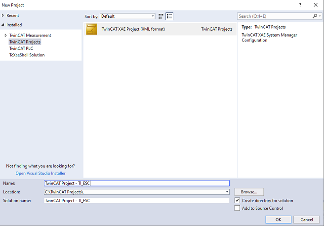
{TWINCAT_INSTALL_DIR}\TwinCAT\3.1\Config\Io\EtherCAT folder.${SDK_INSTALL_PATH}/source/industrial_protocols/ethercat_slave/beckhoff_stack/esi/TI_ESC.xmlCreate a new TwinCAT XAE Project (XML format) by going to "File -> New -> Project -> TwinCAT Project"
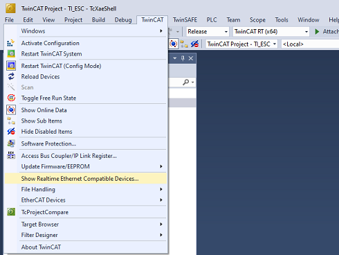
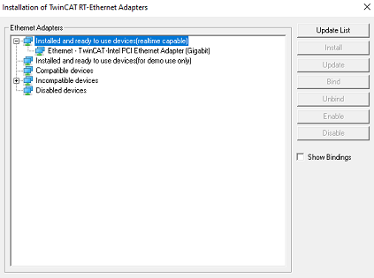
Go to "TwinCAT -> Show Real Time Ethernet Compatible Devices and Install TwinCAT RT Ethernet intermediate driver". For best performance, it is recommended to use a compatible NIC card listed in Supported Network Controller by Beckhoff Ethernet Driver . For the first time only you need to set the PC’s Ethernet port, which is used as the EtherCAT port. Go to "TwinCAT -> Show Realtime Ethernet Compatible Devices"
| 
|
AM243X-EVM | 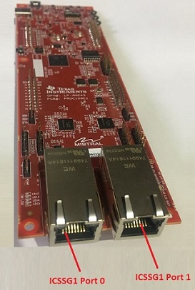
AM243X-LP |
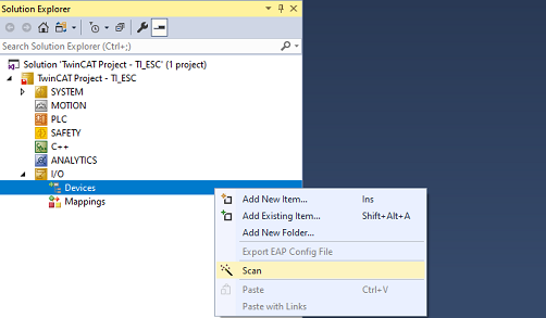
In Solution Explorer, go to "TwinCAT project -> I/O -> Devices". Right click on Devices and select Scan. Press OK in the next dialog to start scanning for EtherCAT devices.
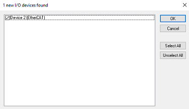
Once an EtherCAT compatible device has been detected on this Ethernet port, the following dialog shows up. Note that there is a tick mark next to the adapter to which the EVM is connected. Press OK and confirm to start "Scan for boxes".
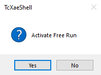
TI Box n(TIESC) will be detected automatically. The TI device will be listed "Box n (TIESC-*)". Press Yes to activate Free Run. This will put TI ESC into OP mode. TIESC number is based on the platform and application. Please check the ESI file for more details.
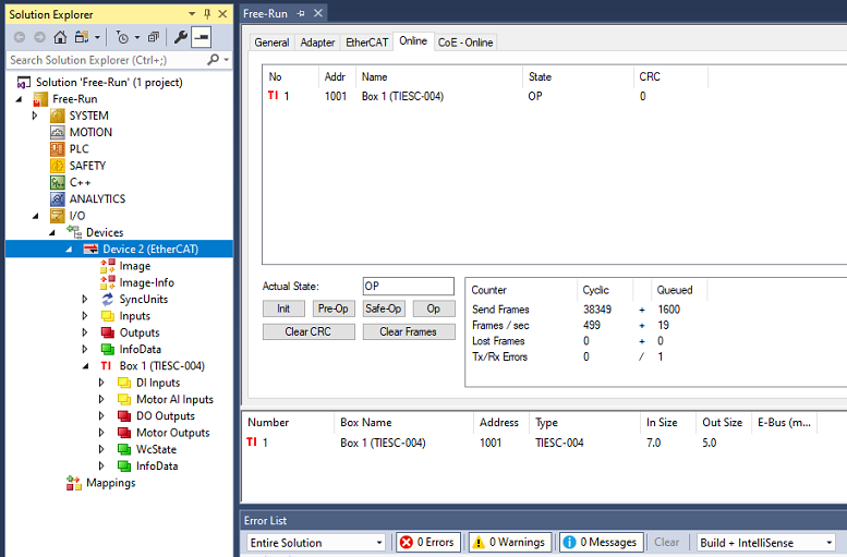
The EtherCAT device state can be displayed by selecting a Device (Double click on Device) and then selecting the Online tab. The device should be in the OP state with no Lost Frames or Tx/Rx Errors.
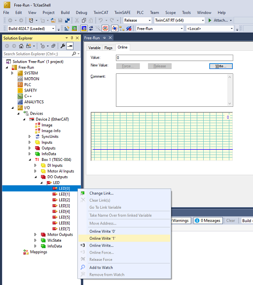
The user can control 8 digital out LEDs using TwinCAT. LED[0] to LED[7] in "Box n (TIESC-*) -> DO Outputs -> LED". Each LED can be turned on and off by selecting "Online write 1" and "Online write 0" respectively.
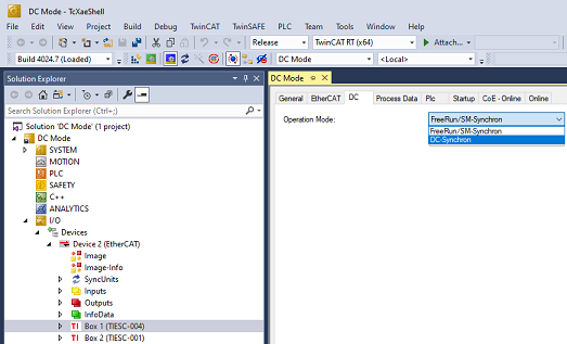
Choose DC Synchronization for all devices in the chain. Click on Box n (TIESC-*). Open the DC tab, and choose DC-Synchron option in Operation Mode. Do this for all slaves in the chain.
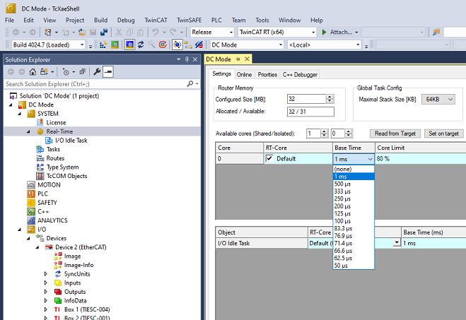
In Solution Explorer, go to TwinCAT project, select "SYSTEM -> Real-Time". In the Settings tab, choose the desired Base Time. With compatible NIC cards, a base time of as low as 50 us can be chosen.
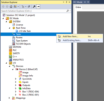
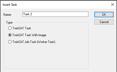
Right-click on "SYSTEM -> Tasks". Click "Add New Item" on the pop-up menu. Select "TwinCAT Image with Task" in the next dialog box. Type a name for the task, and choose OK.
| 
|
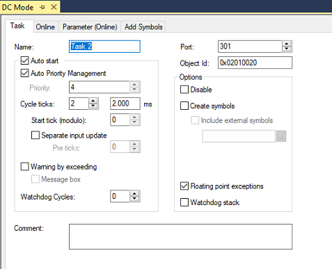
Choose "Auto start" for the task. Choose 2 cycle ticks’ frequency for the task.
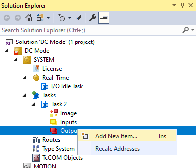
Add an output variable to the task. Right-click on "[Task name] -> Outputs", and choose "Add New Item". You may choose default options for the variable.
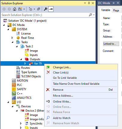
Link the variable to an output for the last slave in the chain. Right-click on [Variable name], and choose "Change Link...".
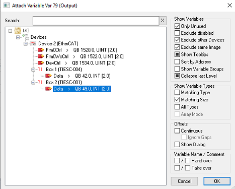
Choose an output from the last slave. You may need to choose "All Types" in "Show Variable Types".
 "Activate Configuration" button on the toolbar.
EtherCAT Slave Beckhoff SSC Example is expected to be used with ${SDK_INSTALL_PATH}/source/industrial_protocols/ethercat_slave/beckhoff_stack/esi/TI_ESC.xml file. If the application is modified to work with a different ESI XML file, user will need to update the corresponding ESI header file (tiesc_eeprom.h) and rebuild the application project.
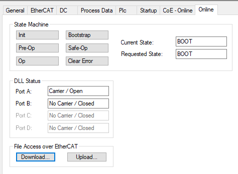
${SDK_INSTALL_PATH}/tools/bin2c folder. Example usage is shown below. "const unsigned char tiesc_eeprom[]" array in ${SDK_INSTALL_PATH}/examples/industrial_protocols/ethercat_slave_beckhoff_ssc_demo/am243x-evm/tiesc_eeprom.h file with the data generated in new_tiesc_eeprom.h file within the brackets following "#define NEW_TIESC_EEPROM"."const unsigned char tiesc_eeprom[]" array in ${SDK_INSTALL_PATH}/examples/industrial_protocols/ethercat_slave_beckhoff_ssc_demo/am243x-lp/tiesc_eeprom.h file with the data generated in new_tiesc_eeprom.h file within the brackets following "#define NEW_TIESC_EEPROM".tiesc_eeprom.h file with new header file.Click "Bootstrap" button. This will take the Slave to BOOT state.

Once the state has changed to "BOOT", Click "Download" button.
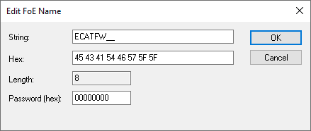
Rename your EtherCAT application binary (.appimage file) as ECATFW__, and use this file as your new EtherCAT application.
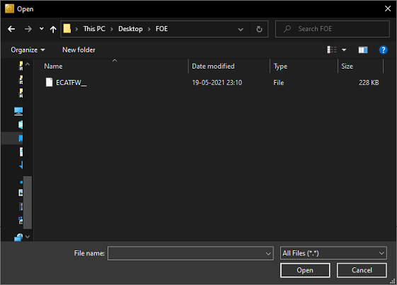
Click OK on the new dialog shown.
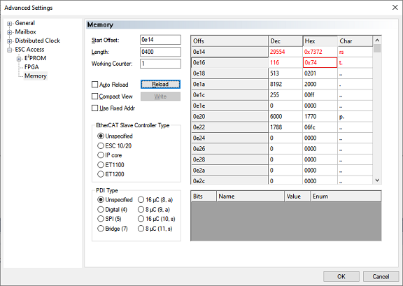
Perform a warm reset by writing "RST"(0x545352) or "rst"(0x747372) to ESC Reset(0x0E14-0x0E17) register to reload the application. Power restart of the EVM will also load the new application.
 1.8.20